Ormandy Group Breeze Installation and operation manual

Breeze
Plate Heat Exchanger
Operating &
Maintenance Manual

VERY IMPORTANT - PLEASE READ CAREFULLY
Running Section 1
Safety Points 1.1 Page 1
Start Up 1.2 Page 1
Working Principles 1.3 Page 2
Installing Section 2
Installation 2.1 Page 3
Operation and Set Up 2.2 Page 4
Health Section 3
Maintenance 3.1 Page 12
Service 3.2 Page 12
Spares 3.3 Page 12
Information Section 4
Specication 4.1 Page 13

1
1. Running
1.1 Safety Points
• During operation, the unit may have very hot or cold surfaces.
• Thetemperatureprobeisinstalleddirectlyinthesecondaryow.Do
notremovewhenthesystemishot,fullofwaterorunderanypressure.
• Takecarewhenlifting.Onlyusethedesignatedliftingpoint.Useonly
certiedliftingequipmentcapableofliftingtheweight.Residualwater
may also be present and spillage could occur.
• NeverlifttheOrmandyRycroftBreezebyanyassociatedpipeworkor
pipe connections.
• Takecarewhenhandling,assomeedgesmaybesharp.
• Theequipmenthasdangerfromelectricity.Donotremovecoversor
allowanyexposedliveparts.Isolatebeforeworkingontheunit.
• The electrical and mechanical functionality must be considered prior
toconnectinganynonfactoryttedequipment.E.g.pumps,valves,
actuators etc.
• PowersupplyandcontrolsignalcablesMUST be segregated as far as is
reasonably practical.
• Shielded control cables must be used.
• Localauthorityregulationsmustbefollowedatalltimes.
• Ensurealloperationsarecarriedoutbysuitablytrained/qualied
personnel.
Checks Complete (✓)
Check that electrical installation is complete.
Check that the mechanical installation is complete.
Checkthatthesystemhasbeenushed,butNOT through the plate pack and
that there are no leaks.
Check that any air has been eliminated from the system.
Checkthatvalvesareopenedintherequiredsequence.
1.2 Start Up

2
TheBreezecomprisesofaSupapacPlateHeatExchanger,eithera3portor4portcontrolvalve,
primary pump, temperature sensor and PID controller, all mounted on a skid base.
Motorised3or4portcontrolvalves,allowrapidadjustmentoftheprimaryheatinputtomatch
changesinsecondaryhotwaterdemand.
TheBreezeissuppliedwithoutinsulationandthedesignensuresthattheoutlettemperaturedoesnot
fallbelowthesetpoint(60°Cdefault)butcanbeadjustedtosuitcustomerrequirementsand
consequentlyreducestheriskoflegionnairesdisease.
Providingtheclassofaccommodationanddetailsofthenumberandtypeofxturesareknown,
OrmandyRycroftwillbepleasedtorecommendtheoptimumsizeoftheBreeze.
With buer vessel to form a semi-instantaneous water heater
3 Port Valve
Primary
Flow
Primary
Return
Secondary
Inlet
Secondary
Outlet
Control
Stat
PHE
4 Port Valve
Primary
Flow
Primary
Return
Secondary
Inlet
Secondary
Outlet
Control
Stat
PHE
1.3 Working Principles
SecondaryFlow
Temperature Gauge
Pressure Gauge
Expansion
Vessel
Expansion
Relief
Valve
Lockshield
Valve
Cold Feed
Non-Return
Valve
Circulating
Pump
Secondary
Shunt Pump
Drain
Pressure/Temp
Relief Valve
Temperature
Sensor
Commissioning
Valve
Drain
Plug
Primary
Return
Actuator
Primary
Feed
Primary
Pump

3
Foundations
The Ormandy Rycroft Breeze should be mounted on prepared foundations that are level.
Lifting
One lifting point is provided on the top of the Breeze control panel bracket.
Avoid the use of chains as the links may cause damage.
Caution: Never lift or move the Breeze-Plate by its pipework or pipe connections.
Pipework
Makesurethatthepipeworkangesaresquareandcorrectlyspacedbeforeboltingup.Ensurethat
theweightofthepipeworkistakenbyexternalsupportsandnotbytheOrmandyRycroftBreezeplate
connection.Allowancesshouldbemadeforexpansionofthepipes,eitherbysuitablebendsor
exiblejoints.Tightenangeboltsinadiametricallyoppositesequenceandnotconsecutivelyround
eachange.
Connections
ThethreadedconnectionmaybesealedwithPTFEtape.Flangedconnectionsshouldbesealedwitha
suitable gasket and sealing agent.
Liquid Expansion
Changesinvolumewithtemperaturemustnotbeoverlooked.Thesystempressurewillrise
dramaticallyifthereisnowhereforwatertoexpand.Itisnotadvisabletouseareliefvalveasa
meansofreleasingtheexcesswater.
Ventedsystemsexpansionisviatheventpipewhichdischargesbackintotheatmospherictank.
Unventedsystemsrequireaseparateexpansiontank.
Venting
VentvalvesmustbettedatthehighestpointintheconnectingpipeworksothattheOrmandyRycroft
Breeze can be bled of air prior to operating. It is also essentialthattheoodedcantypepump
motors,whicharecommonlyusedformostOrmandyRycroftBreezeunitsarealsobledofair
before use.
2. Installing
2.1 Installation
Filling
Beforellingthesystem,checkthatthedrainvalveisclosedandallairventsareopen.
Flush out the system before installing the Ormandy Rycroft Breeze-Plate to remove any foreign
matter. Close any manual air vents and run the Breeze. Crack the vents to release air.
Caution: Do not ll the system too quickly, otherwise pockets of air may become trapped.
Do not ush the system through the plate heat exchanger, as this could result in the plates
becoming blocked or cause a loss in performance.

4
The Electrical connections are located in the terminal compartment. A description of the terminals can
be found on the inside of the terminal compartment cover.
Connectasinglephase230V50HzsupplytotheMainsInputterminals.Themaximumfullloadcurrent
is16A,withthemajorityofunitsbeingconsiderablyless.
Iftheunitistobecontrolledremotely,connecttheremotecontrolswitchorcontactstotheRemote
enableterminals.Iftheunitistobecontrolledlocally,talinkbetweentheseterminals.
Do NOT apply voltage to these terminals!
Voltage free fault relay contacts are provided for Remote Fault Indication.
13 System Healthy Indicator
14 System Fault Indicator
15 ValvePositionBarDisplay
16 On/Offswitch
1 Day/Mode Display
2 Time/Alarm Display
3 Temperature/Parameter Display
4 High Temperature Alarm Indicator
5 ResetPushButton
6 StepLeftPushButton
7 Value Increase Push Button
8 Step Right Push Button
9 Value Decrease Push Button
10 ModeSelectPushbutton
11 Pump Energised Indicator
12 PowerOnIndicator
Terminal Block
2.2 Operation and Set Up
Electrical Connections
Key to Ormandy Rycroft Breeze controls and indicators.
1 2 3
45
6
7
8
910
11
12
13
15
14
16 ✓
✘
100
50
0
1
3
6
2
54
7
On/Off
Switch

5
Operation
TheBreezeisaself-containedunit,whichcontrolsuptotwoprimaryandtwosecondarypumps
togetherwitha3or4-portvalvetoprovidehotwater.Whenthesystemisttedwithtwoprimary
pumpstheyareoperatedonasharedduty-standbycyclewithautomaticchangeoveronpumpfailure.
a) Remote Switch or Building Management System Control
TheBreezewillbeturnedonwhencontactsconnectedtotheRemote Enable terminals are
closed.Thisallowstheusertocontrolthetimeofdaywhenhotwaterwillbeavailable.
When the contact is open the system is turned off.
b) Internal Time Clock Control
ForthisfunctiontoworktheTimeclockfunctionshouldbeturnedon(seeSetUp)andthe
Remote Enable terminals should be linked.
UnderTimeclockcontroltheBreezewillbeturnedonandoffatpresettimesoftheday.
Uptotwoonandtwoofftimescanbeprogrammedforeachdayoftheweek.
Thesystemcanbere-activatedafterithasautomaticallyswitchedoffbypressingthe
Value Increase (7)pushbutton.Eachpressofthispushbuttonwilladd30-minuteincrementsto
atotal,whichisshownintheTime/Alarmwindow.PressingtheValue Decrease (9) push button
willsubtract30-minuteincrementsfromthetotaltime.
Thetimevaluecountsdownandwhenthetimeshownhaselapsed,theunitwillrevertto
normal time clock operation.
c) Remote Switch and Internal Time Clock Control
Forthisfunctiontowork,theTimeclockfunctionshouldbeturnedon(seeSetUp)anda
remote ControlswitchshouldbeconnectedtotheRemote Enable terminals.
UnderTimeclockcontroltheBreezewillbeautomaticallyturnedonandoffatpreset
timesoftheday.Uptotwoonandtwoofftimescanbeprogrammedforeachdayoftheweek.
When contacts connected to the Remote Enable terminalsareopenedtheBreeze-Platewillbe
turned off.
When remotely enabled and the system has turned off under time clock control, it can be
re-activated by pressing the Value Increase (7)pushbutton.Eachpressofthispushbuttonwill
add30-minuteincrementstoatotal,whichisshownintheTime/Alarmwindow.Pressingthe
Value Decrease (9)pushbuttonwillsubtract30-minuteincrementsfromthetotaltime.
Thetimevaluecountsdownandwhenthetimeshownhaselapsed,theunitwillswitchoffand
reverttonormaltimeclockoperation.However,whenthesystemhasbeenturnedoffunder
remote control, it cannot be re-activated by pressing the Value Increase (7) push button.
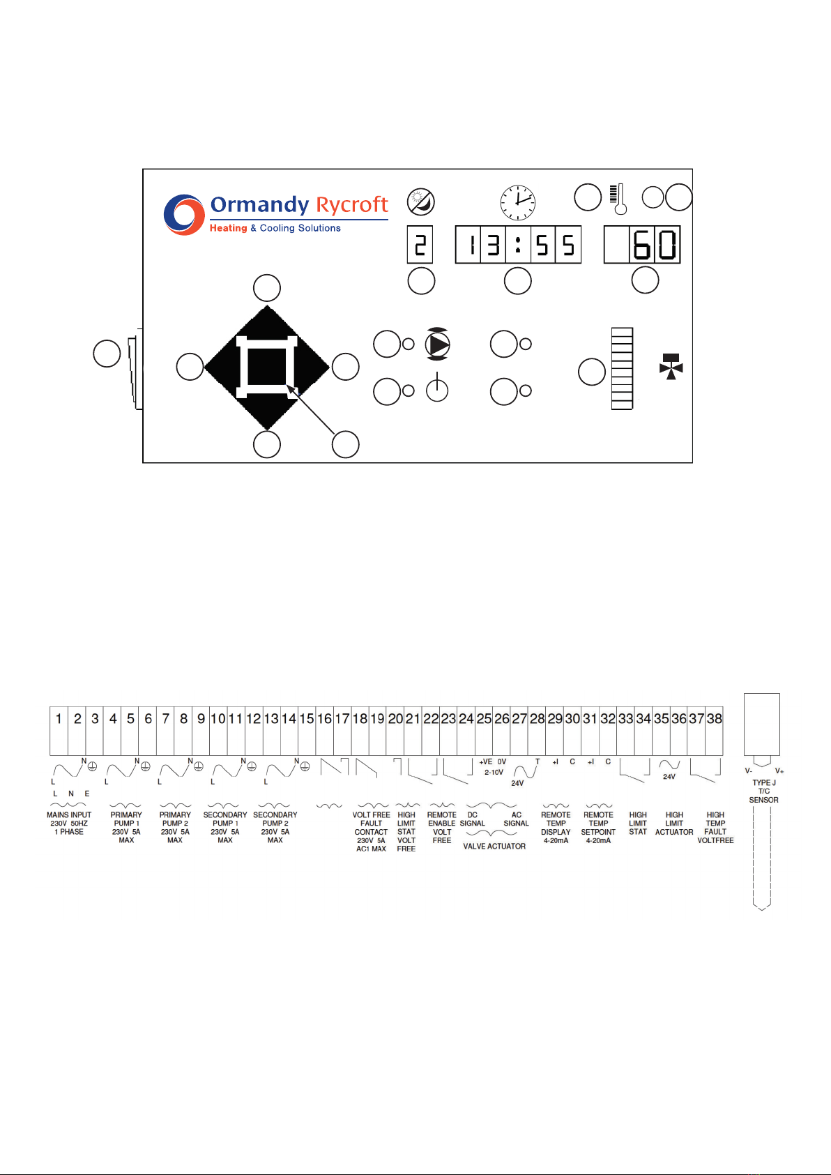
Switchonviaswitch(16)
Thefrontpanelwillilluminate.Afterafewsecondsofselfchecks,thedisplayswillsettletotheDay (1)
(Time-clockonly),Time (2) and Temperature (3).Thepumpswillstart(11),thevalvewillopen(15)
and the system healthy indicator (13)willilluminate.
Thestandardtemperaturesettingis60°Candtheunitwillruncontinuously.(24houroperation).
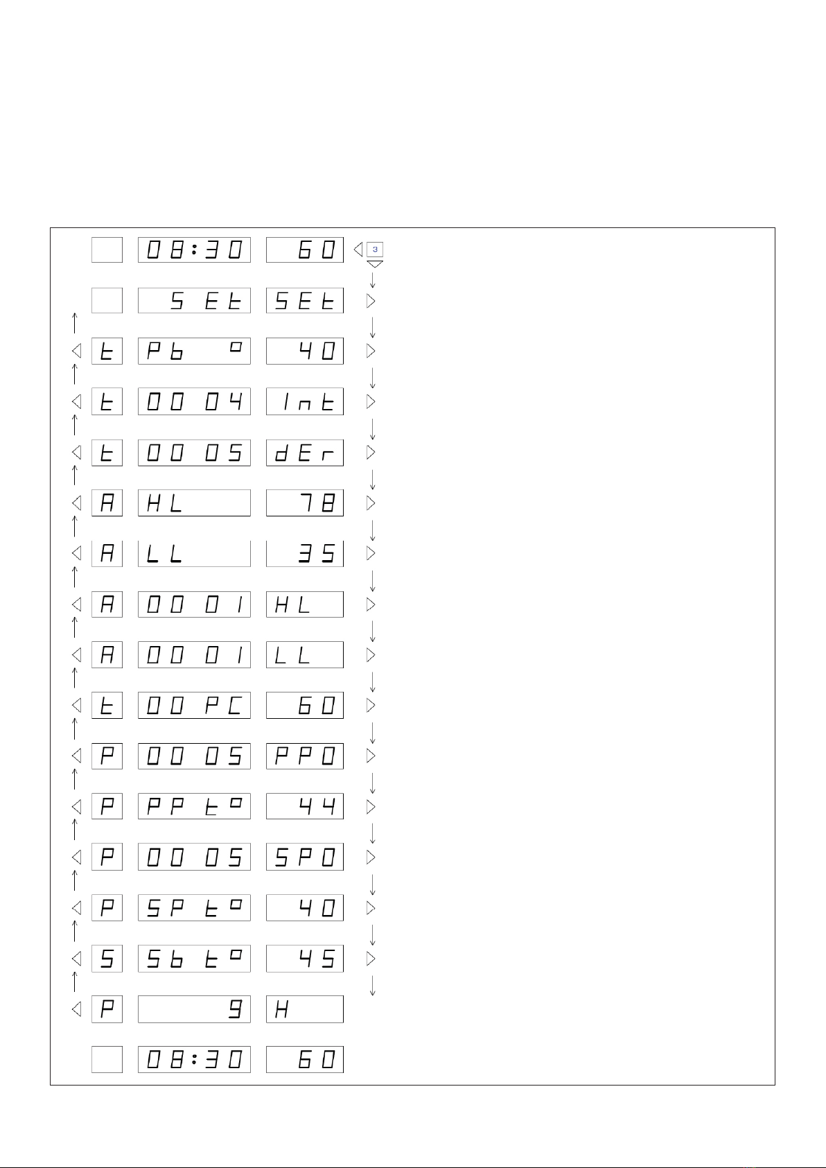
To change any of the default settings, refer to Figure 3
TheBreeze-Platecanbeenergisedbyitsowninternaltimeclockfunction,byaremoteswitchor
BuildingManagementSystemorbyacombinationofthetwo.

6
Set Up
TheBreezecontrolunitisfactoryprogrammedwithtemperatureandcontrolsettingsthatwillsuit most
applications.Howeverwewouldrecommendthattheunitiscommissionedtoensurecorrectoperation
andmaximumefciency.ContactourServiceDepartmentfordetails.
Allthevaluesareadjustablesothatyoucancustomisetheunittoexactlymatchyoursystem.
The set up routine is entered by pressing and holding the Mode (10) push button for three seconds.
Press the Step Right (8) and Step left (6)pushbuttonstomoveforwardsandbackwardsthroughthe
sequence.PresstheValue Increase (7) or Value Decrease (9)pushbuttonstoalterthevalueshownin
the display. Press and hold the Mode (10)pushbuttonfor3secondstoexitthesetuproutine.
Thesystemcontinuestocontrolwhenthecontrollerisinthesetuproutine,allowingadjustmentsto
bemadeonthey
Figure 1 - Set Up Sequence
Press and hold for a minimum of 3 seconds
to enter Set Up routine.
Press Step Righttomovetorstvalue.
Press Value Increase or Value Decrease
pushbuttonstoalterwatertemperature.
Press Value Increase to turn Time
clock function on or off.
Press Value Increase or Value Decrease
to change Day number.
Press Value Increase or Value Decrease
push buttons to change time. Press and
hold push button for rapid change.
Press Value Increase or Value Decrease
push buttons to change the time of the
rsttimedonandoffperiod.Pressand
hold push button for rapid change.
Press Value Increase or Value Decrease
push buttons to change the time of the
second timed on and off period. Press and
hold push button for rapid change.
Press Step Right push button to set the
on-off times for day 2, day 3, day 4 etc.
Press and hold Value Select push button
foraminimumof3secondstoexitSetUp
routine.

7
System Faults
When a fault situation is detected, the System Fault (14)indicatorwillbelitandtheinternalFaultrelay
willbeenergised.Thenormaltimeandtemperaturedisplaywillbereplacedbyanalarmmessage.
ThemessagesandmeaningsareshowninFigure2below.Ifasystemfaultoccurswhenthecontroller
is in the set up routine, the System Fault (14)indicatorwillbelit,butthedisplaywillnotbereplacedby
analarmmessage.ThealarmmessagecanbeviewedbyleavingtheSetUproutine.
First High temperature level detected.
Second High temperature level detected -
buzzer sounds and the system is
automaticallyshutdown.
Lowtemperaturedetected.
PrimaryPumpNo1failure-iftwoprimary
pumpsarettedPrimaryPumpNo2willbe
energised.
Primary Pump No 2 failure - Primary Pump
No 1willbeenergised.
SecondaryPumpNo1(shunt)failure-
system isautomaticallyshutdown.
SecondaryPumpNo2(re-circulation)
failure -systemisautomaticallyshutdown.
Thermo-couple failure - the system is
automaticallyshutdown.
System has been remotely disabled
TheSecondHightemperaturelevelalarmwillautomaticallyshutthesystemdownandsounda
warningbuzzer.ThebuzzercanbesilencedbypressingtheReset (5) push button. When the fault has
been diagnosed and corrected, the system can be re-activated by pressing the Reset (5) push button
again.Thiscanonlybeperformedwhenthetemperatureshavereturnedtonearnormal.Alltheother
alarmswillautomaticallyresetwhentheproblemhasbeencorrected.Alarmsconstantlyre-occurring
couldindicatethatthesystemhasbeenincorrectlycongured.
Advanced Set Up Routine
Thesystemissuppliedwithdefaultsettings,whichsuitmostapplications.Theadvancedsetupfeature
allowsInstallersandEngineerstotailorthesettingstosuitparticularinstallations.Thesystem
continuestocontrolwhenthecontrollerisintheadvancedsetuproutine,soresultsofadjustments
can be seen immediately. In addition, manual control of the valve position is available.
Figure 2 - Alarm Messages

8
The set up routine is entered by simultaneously pressing and holding the Mode (10), Step Left (6) and
Value Decrease (9), Push buttons for a minimum of three seconds. Press the Step Right (8) and Step Left
(6)pushbuttonstomoveforwardsandbackwardsthroughthesequence.PresstheValue Increase (7)
or Value Decrease (9)pushbuttonstoalterthevalueshowninthedisplay.PressandholdtheMode (10)
pushbuttonfor3secondstoexitthesetuproutine.
Figure 3 - Advanced Set Up
Press and hold for a minimum of 3 seconds to enter
Advanced Set Up routine.
Press Step Rightpushbuttontomovetotherst
setting value.
Press Value Increase or Value Decrease push
buttons to alter Proportional Band.
Press Value Increase or Value Decrease push
buttons to alter Integral Time.
Press Value Increase or Value Decrease push
buttons to alter Derivative time.
Press Value Increase or Value Decrease push
buttons to alter First level High temperature limit.
Press Value Increase or Value Decrease push
buttonstoalterLowTemperatureLimit.
Press Value Increase or Value Decrease push
buttons to alter High Temperature Limit Time Delay.
Press Value Increase or Value Decrease push
buttonstoalterLowerTemperatureLimitTimeDelay.
Press Value Increase or Value Decrease push
buttonstovaryvalveposition.Figureshows
percentage open. See Manual Control.
Press Value Increase or Value Decrease push
buttons to alter Primary Pump over-run time.
Press Value Increase or Value Decrease push
buttons to alter Primary Pump over-run temperature.
Press Value Increase or Value Decrease push
buttons to alter Secondary Pump over-run time.
Press Value Increase or Value Decrease push
buttons to alter Secondary Pump over-run temperature.
Press Value Increase or Value Decrease push buttons to
alter the Night Set-back/Pasteurisation temperature.
Press Value Increase or Value Decrease push
buttons to alter Primary Pump duty - standby time.
Press and hold Modepushbuttonfor3secondstoexit
Set Up routine.

9
Night Set Back / Pasteurisation
When the DIPswitch (column5inthetablebelow) for Night set-back/Pasteurisation is set to the on
positionandtheunitisputintostandbyviathetime-clock.Whenthepasteurisationvalue(SSBTO)is
settoabovethenormalsettemperature(SSETTO),thecontrollerwillassumepasteurisationandwill
raise the temperature to the pasteurisation value for one hour, before returning to standby, until the
nextscheduledonperiod.
Alternatively,whenthesetbackvalueissettobelowthenormalsetvalue,thecontrollerwillassume
setbackandwilllowerthetemperaturetothisvalueuntilthenextscheduledperiod.
Manual Control
TheAdvancedSetUproutineallowstheengineertopositionthecontrolvalvemanually.Thisfeatureis
activewhilethissetupwindowisvisible.Thisfeatureisdisabledandcontrolrestoredtoautomaticby
pressing the Step Left (6), or Step Right (8) push buttons to display another parameter or pressing and
holding the Mode (10),pushbuttontoexittheadvancedsetuproutine.
(Seepage4forkeytonumberreferences).
Remote Set Point Adjustment
Whena4-20mAsignalisconnectedtotheremoteinput,thesetpointcanbevariedbetween
20degC=4mAandl00degc=20mAattherateof5degreespermilliamp.
Itshouldbenotedthattheexternalcontrolsignalassumescontrolassoonasthemilliamplevelrises
above2mA.Consequently,ifthecontrollerlosesthissignal,itrevertsbacktoit’sowninternalsetpoint.
DIP Switch Settings
ThephysicalcongurationofthesystemandtheNightSet-back/pasteurisationfunctionsare
programmedintothecontrollerbysettingthepositionofeightswitches.Theswitchesarelocatedon
thedisplayprintedcircuitboard.Tochangethepositionoftheseswitches:
1) Isolatethemainssupplytothecontroller.
2) Openthehingeddoor.
3) Removethefourxingscrewsandslidethecontrolfaciaoutoftheenclosuretakingcare
not to pull the connecting cable.
4) Turnthefaciaover.DIPswitchesarelocatedonthebottomedgeofthecircuitboard.
5) Changetheswitchpositionsasrequired(seetablebelow)
6) Replacefacia,closehingeddoorandswitchonthemainssupply.
1 2 3 4 5 6 7 8 Function
O
O
O
O
O
On
On
O
Thefollowingtableshowstheswitchcontrols.(Boldpositionsarefactorydefaultvalues).

10
Set Up:
Factory Default Settings
Set Set:

11
By pressing the reset (5) and mode (10)buttonssimultaneouslyforafewseconds,thetimeclock
settingswillbereturnedtothefactorydefaultsettings.
By pressing the reset (5) and decrease (9)buttons,thecontrolandalarmparameterswillbereturned
to the factory default settings.

12
Wherepossible,adetailedinspectionoftheBreezeshouldbemadeaftertherstsixmonths.This
willprovideaninsightintofuturerequirementsforefcientmaintenance.IftheBreezeiscleanedand
thereisnosignofcorrosion,itcanbesafelyassumedanannualinspectionwillbesufcientforfuture
servicing. All electrical connections should be checked and tightened if necessary.
Caution:-Maintenanceshouldonlybeperformedbyqualiedpersonnelonly.Electricalworkshouldbe
carriedoutbyaqualiedelectricianinstrictconformancetothelatestrequirements.
InordertomaintaintheBreezeunit,youwillrequireasaminimumthefollowingtoolkit:
• SetofMetricallenKeysuptoM16
• Set of Metric spanners
• SetofScrewdrivers
• Apipewrenchtosuitamaximum50mmnominalpipesize.
• M16frictionratchetandM16deepringspanner(CP-B25toCP-B250)
Controller
The controller is run via an EPROM that stores all the changes to the time programmes and other data.
Aftertherstsixmonths,allconnectionsinthepanelshouldbecheckedandtightenedifnecessary.
Temperature Thermocouple
EnsurethattheThermocoupleconnectionsaresatisfactory.Refertothemanufacturer’sinstructions.
Control Valve and Actuator
Checkthatthevalvewillopenandclosebyusingthemanualfacilityonthecontroller.Electrical
connection should be checked at the actuator. The linkage should also be tightened to ensure good
mechanicalcontact.Refertothemanufacturer’sinstructions.
Hi-Limit / Control Valve and Actuator
Inadditiontotheabove,checkthatthevalveopensandclosesbyturningthepoweronandoff.
Electrical connection should be checked at the actuator. The linkage should also be tightened to ensure
goodmechanicalcontact.Refertothemanufacturer’sinstructions.
Primary Pump
Ensurethatthepumpisonthecorrectspeedsettingandthatwiringissecureatallterminals.
Plate Heat Exchanger
Aseriesofcontouredplateswithportsformaplatepackwithowchannels.Thehotwaterowsdown
alternatechannels,whilethecoldwaterowsupalternatechannels.Thiscreates100%counterow.
Ormandy Rycroft Engineering offers a full and comprehensive range of service and support. This en-
compassesthemaintenance,commissioningandrepairofgeneralwaterheatingequipment,
includingheatexchangers,boilers,pressurisationunits,boostersetsandcaloriers.
AllBreezecomponentpartsareavailableasreplacement/spareitems.Pleasequoteasmuch
informationaspossibletoallowthesupplyofthecorrectpart(s).Serialnumber,photosetc.
3.1 Maintenance
3. Health
3.2 Service
3.3 Spares

13
Power Supply Requirements
Voltage:230Volts,50Hz.
Nominalcurrent:Maximum16Amps(PumpandDutydependant).
Inputs
Temperatureprobe:TypeJthermocouple(Grounded)viaa12bitA/D
converter(minimum0.1°Cresolution).Displayrange:0-250°C
Volt Free Contacts
Toenablefromremotesource(Time-clock,SCADA,BMS,boilercontrolsetc)
For connection of a supplementary high limit contact or thermostat as a second alarm.
PrimaryPump(s)faultcontact/s.
Signal
Remotesetpointadjustment.4-20mAScaled20°C-100°C.
Outputs
Pump Supply
• Twoprimarypumps(1Duty,1Standby)singlephase230v5AMaximum.
• Twosecondarypumps(1circulation,1shunt)singlephase230v5AMaximum.
Valve actuator supply
• 24v.a.c20VAMax
• Controlsignal2-10v/0-10.d.c0.1mA,Max.
• Theeffectivecontrolsettingrange0-85°C.
Volt Free Contacts
Changeover fault contact for remote alarm on fault, to SCADA, BMS, Annunciator etc.
Signal
Remoteindicationofprocessvariable.4-20mAscaled0°-100°C.
*NOTE: The volt free contact terminals must not have voltage applied to them.
4.1 Specification
4. Information

Duncombe Road,
Bradford, England BD8 9TB.
Telephone:+44(0)1274490911.Email:[email protected]
www.ormandygroup.com
Table of contents
Popular Industrial Equipment manuals by other brands

HunterDouglas
HunterDouglas Luxalon Profix Installation instruction

HunterDouglas
HunterDouglas Luxalon 84B installation instructions

Cold Jet
Cold Jet i3 MICROCLEAN 2 manual

Oriental motor
Oriental motor EZS Series operating manual

Ecotech
Ecotech DW 45 Manual for use and maintenance

Atronix
Atronix PPS Solar flex user manual