Orno OR-NL-379WLR5 User manual

PG 6 PG 1
Pack contents:
1 x LED floodlight with
PIR complete with 3 core
2
1.0mm x 0.8m rubber
cable and quick fix
mounting bracket
These instructions are provided as a guideline to assist you.
PLEASE READ THESE INSTRUCTIONS BEFORE INSTALLATION
AND RETAIN FOR FUTURE REFERENCE
Model:
10W / 20W / 30W LED Floodlights With PIR
INSTALLATION INSTRUCTIONS
A guide for qualified electricians
1M
10W
20W
30W
LAMP SPECIFICATIONS: 10W 20W 30W
Lumens total flux 700 lm 1400 lm 2100 lm
Rated Wattage 10W 20W 30W
Nominal life time of the lamp 25 000 hrs 25 000 hrs 25 000 hrs
Colour temperature 5000K 5000K 5000K
Number of switching cycles
before premature lamp
failure
15,000 15,000 15,000
Warm-up time up to 60 % of
the full light output Instant full light Instant full light Instant full light
Dimmable No No No
LED array dimensions (L/H) 40 x 15mm 70 x 15mm 60 x 25mm
Nominal beam angle 120° 120° 120°
Rated power 10W 20W 30W
Rated lamp lifetime 25 000 hrs 25 000 hrs 25 000 hrs
Lamp power factor >0.5 >0.5 >0.9
Lumen maintenance factor at
end of nominal life 70% 70% 70%
Starting time <0.5s <0.5s 0.5s
Colour rendering >80 >80 >80
Colour consistency Within 6 step
Macadam ellipse
Within 6 step
Macadam ellipse
Within 6 step
Macadam ellipse
Rated peak intensity 231.45cd 450cd 720cd
Rated beam angle 120° 120° 120°
Voltage 85-265V~ 85-265V~ 85-265V~
Not suitable for accent lighting
OR-NL-379WLR5
OR-NL-379GLR5
OR-NL-380WLR5
OR-NL-380GLR5
OR-NL-392WLR5
OR-NL-392GLR5
PRODUCENT
ORNO-LOGISTIC Sp. z o.o.
ul. Katowicka 134
43-190 Mikołów
tel. 32 43 43 110
www.orno.pl

To avoid damage to the unit do not aim sensor
towards sun.
Avoid positioning the sensor unit adjacent to a
bright light source which may prevent the unit from
operating when the lux control is set to operate in
dark conditions.
Avoid nuisance / false triggering by directing sensor
away from:
• Trees and shrubs
• Reflective surfaces such as smooth white walls
• Swimming pools
• Heat sources such as boiler flues
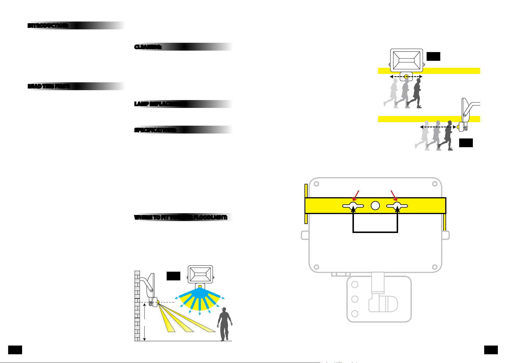
The PIR sensor scanning specifications
(approximately 7 metres at 120°) may vary slightly
depending on the mounting height and location.
The detection range of the unit may also alter with
temperature change. Before selecting a place to
install your PIR floodlight you should note that
movement across the scan area is more effective
than movement directly towards or away from the
sensor. (Refer to fig.2 opposite).
If movement is made walking directly towards or
away from the sensor and not across the sensor
the apparent detection range will be substantially
reduced (refer to fig. 3 below).
INTRODUCTION:
The floodlight incorporates a PIR (Passive Infra Red)
sensing device which continuously scans a preset
operating zone and immediately switches the light
on when it detects movement in that area.
This means that whenever movement is detected
within the range of the sensor the light will switch
on automatically to illuminate the area you have
selected to light. While there is movement within
range of the unit the light will remain on.
READ THIS FIRST:
Check the pack and make sure you have all of the
parts listed on the front of this booklet. If not,
contact the outlet where you bought this product.
This product must be installed by a competent
person in accordance with the current building and
IEE wiring regulations.
As the buyer, installer and/or user of this product it
is your own responsibility to ensure that this fitting
is fit for the purpose for which you have intended
it. Eterna Lighting cannot accept any liability for
loss, damage or premature failure resulting from
inappropriate use.
This product is designed and constructed according
to the principles of the appropriate British Standard.
Switch off the mains before commencing installation
and remove the appropriate circuit fuse or lock off
MCB.
This unit is suitable for outdoor use.
This product is designed for permanent connection
to fixed wiring: this must be a suitable circuit
(protected with the appropriate MCB or fuse).
Before making fixing hole(s), check that there are no
obstructions hidden beneath the mounting surface
such as pipes or cables.
Make sure that the fixings are strong enough to
support the considerable weight of the fitting and
hold it rigidly.
The lamp must be positioned so that there is at
least 1M between the luminaire and any illuminated
surface.
When making connections ensure that the terminals
are tightened securely and that no
strands of wire protrude. Check that the terminals are
tightened onto the bared conductors and not onto
any insulation.
This product must be connected to Earth
termination.
This product is not intended to be used by children
and persons with sensory, physical and/or mental
impairments that would prevent them from using it
safely.
You are advised at every stage of your installation to
double-check any electrical connections you have
made. After you have completed your installation
there are electrical tests that should be carried out,
these tests are specified in the current IEE wiring and
building regulations.
CLEANING:
• To avoid dust build-up and ensure proper
functioning of the floodlight, please wipe the
sensor lens lightly with a damp cloth every 3
months.
• Disconnect the power and clean the exterior only of
this fitting with a moist (not wet) cloth.
• Do not use any chemical or abrasive cleaners.
LAMP REPLACEMENT:
This luminaire has a sealed LED lamp and is
maintenance free. No lamp replacement is required.
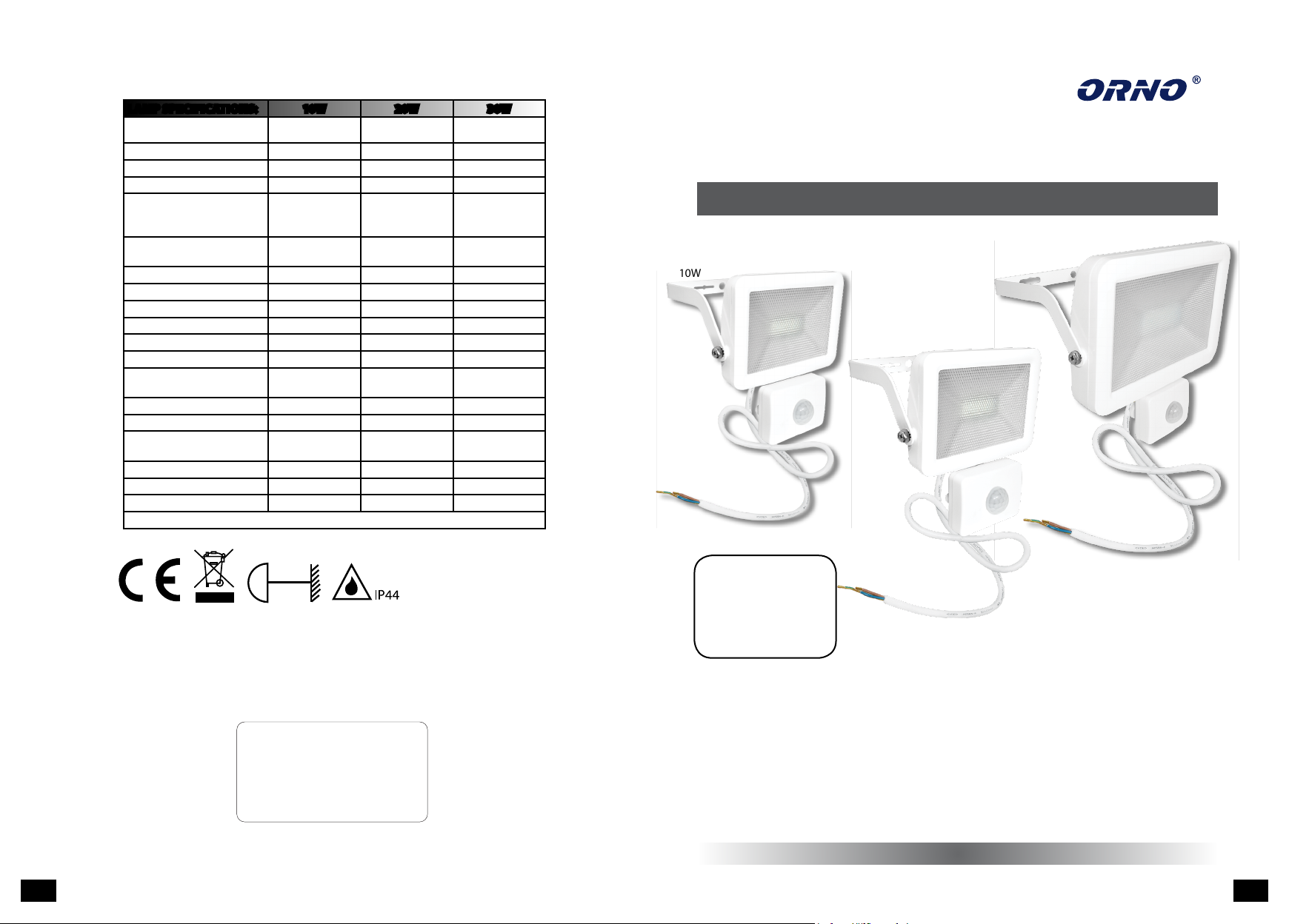
SPECIFICATIONS:
• Detection range: max. 7M at approx. 120° scan
• Duration time adjustment: (10±2) seconds to (7±2)
minutes
• Sensitivity adjustment: 2M to 7M
• Detection circuitry: Passive Infra-Red (PIR)
• Weatherproof: IP44
• Power required: 230V ~ 50 Hz
• Recommended power supply cable: H05RN-F 3G
1.0mm2
• Lux adjustment: 2-2000 Lux
WHERE TO FIT YOUR PIR FLOODLIGHT:
To achieve best results we suggest you take the
following points into consideration:
Do not mount on a surface that has vibration.
Ideally the PIR flood light should be mounted 1.8 to
2.5 metres (6 to 8ft) above the area to be scanned
(refer to fig.1 below).
2.5M
2M 6M 7M
120˚
Approx
Fig 1
EFFECTIVE:
Movement across
scan area
LESS EFFECTIVE:
Movement
directly in front
of scan area
Fig 2
Fig 3
PG 2 PG 3
Fixing slots on bracket
10W: 44mm
20W: 75mm
30W: 119mm

INSTALLATION:
01) Switch off the mains before commencing
installation.
02) Using the bracket as a template mark and then
drill the appropriate fixing holes.
03) Secure the bracket with suitable fixings.
04. Terminate loose ends of wire to an appropriate IP
rated junction box or similar, ensuring the below
is observed.
Live - Brown / Red
Neutral - Blue / Black
Earth - Yellow / Green
05) Adjust the direction of the floodlight and tighten
the head fixings ensuring that you have used the
lock washers.
06) Restore mains power.
07) Adjust the PIR sensor floodlight to the desired
settings.
UNDERSTANDING THE CONTROLS:
(Please refer to Fig. 5 below)
ADJUSTING THE DURATION TIME:
The length of time the unit remains switched on
after activation can be adjusted from (10±2) seconds
to (7±2) minutes approximately. Rotating the TIME
screw from (+) to (-) will reduce the duration time.
Note: Once the light has been triggered by the PIR
sensor any subsequent detection will start the timed
period again from the beginning.
ADJUSTING THE LUX CONTROL LEVEL:
The Lux control module has a built-in sensing device
(photocell) that detects daylight and darkness. The
(R) position denotes that the floodlights can work
at day and night, and the () position only work at
night. You can set to operate the unit at the desired
level by adjusting the LUX screw.
SETTING THE CONTROLS - WALK TEST:
Turn the Lux control screw to light (R) & ensure
that the TIME control screw is set at the minimum
duration time (-) position. The floodlight will now
switch on and remain on for about 10 seconds after
each detection.
01) Adjust time control to required setting.
02) To set the light level at which the floodlight will
automatically switch “on” at night, turn the LUX
control screw from daylight (R) to night (). If
the floodlight is required to switch on earlier, e.g.
dusk, wait for the desired light level, then slowly
turn the LUX control screw towards daylight while
someone walks across the center of the area to
be detected. When the floodlight switches on
stop adjusting. You may need to make further
adjustments to achieve your ideal light level
setting.
ADJUSTING THE SENSITIVITY:
The sensitivity means the maximum distance which
PIR sensor can be triggered by movement - turning
the SENS knob from (+) to (-) will decrease the
sensitivity.
TROUBLESHOOTING AND USER HINTS:
Note: all passive infra red detectors are more sensitive in cold and dry weather than warm and wet weather.
PROBLEM POSSIBLE CAUSE SUGGESTED REMEDY
Light does not switch on
when there is movement
in the detection area.
1. No mains voltage Check all connections, and MCB Fuses / switches
2. Nearby lighting is too bright Relocate the unit
3. Controls set incorrectly Adjust Lux setting
4. Wired incorrectly Check wiring and confirm its wired as per the
wiring instructions opposite
5. Sensor positioned in wrong direction Relocate the unit
Light switches on for no
apparent reason (false
trigger)
1. Heat sources such as air-con, vents, heaters, flues,
other outside lighting, moving cars trees or shrubs
are activating sensor Relocate the unit
2. Interference from on/off switching of electric
fans or lights on the same circuit as your security
floodlight.
(This problem does not always occur but a faulty
switch or noisy fluorescent light may cause the
security floodlight to switch on)
Should the false triggering become, troublesome,
consider:
(a) Replacing a faulty switch
(b) Replacing noisy fluorescent tubes and/or
starters
(c) Connecting the floodlight to a separate
circuit (in most cases where one or more of
the above suggestions have been carried out,
false triggering has been reduced)
3. Reflection from swimming pool, or reflective
surface such as smooth white walls Relocate the unit
Light remains on Time is set too long Reduce time
Light remains on at
nighttime Possible heat source in detection zone
Cover PIR sensor lens with a thick cloth, if the
light turns off check detection area for heat or
reflective source, reposition head and decrease
the sensitivity setting if this control is available
Light switches on during
daylight hours LUX control screw is set to daylight position Turn the LUX control screw to desired light level
setting
When setting the lux
controls in daylight
the detection distance
becomes shorter
Interference by sunlight Re-test at night
Fig 5: PIR Controls
PG 4 PG 5
TIME LUXSENS
This manual suits for next models
5
Popular Floodlight manuals by other brands

Litecraft
Litecraft ILED-MP-07F5-010 user guide

RIGEBA
RIGEBA RG-W15IB15-KF3A user manual

EuroLite
EuroLite AKKU UP-4 QCL Spot WDMX user manual

Terex
Terex AL4000D2 Series Operator, service & parts manual

Larson Electronics
Larson Electronics LEDWP-LP-450-KNL-DCM instruction manual

Elation
Elation Design LED 36MH user manual