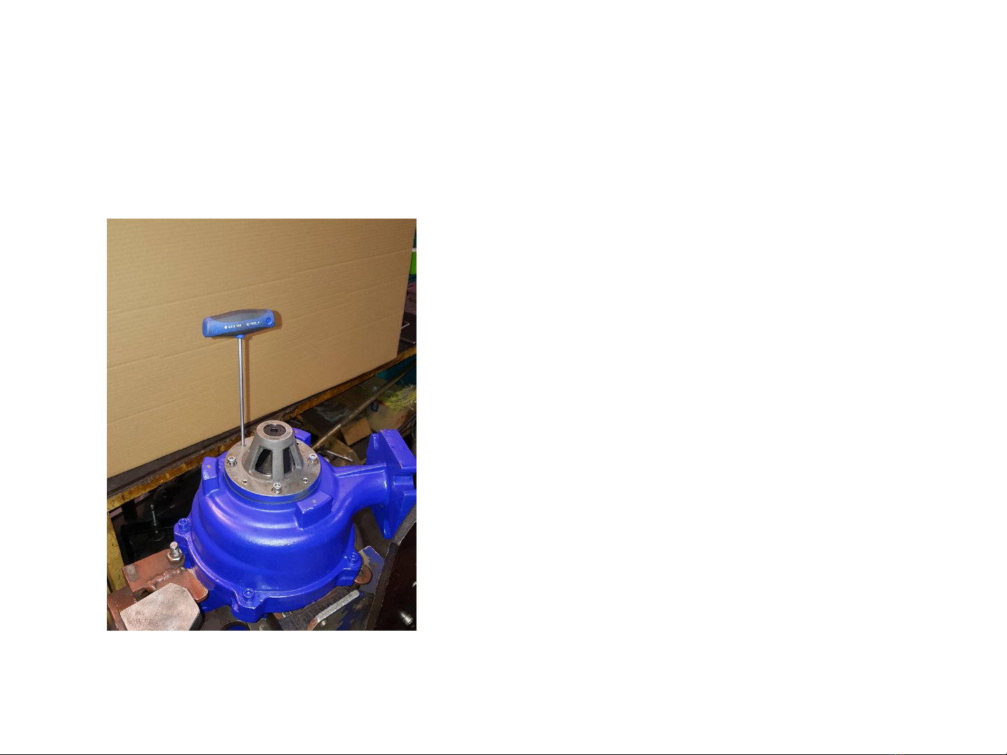
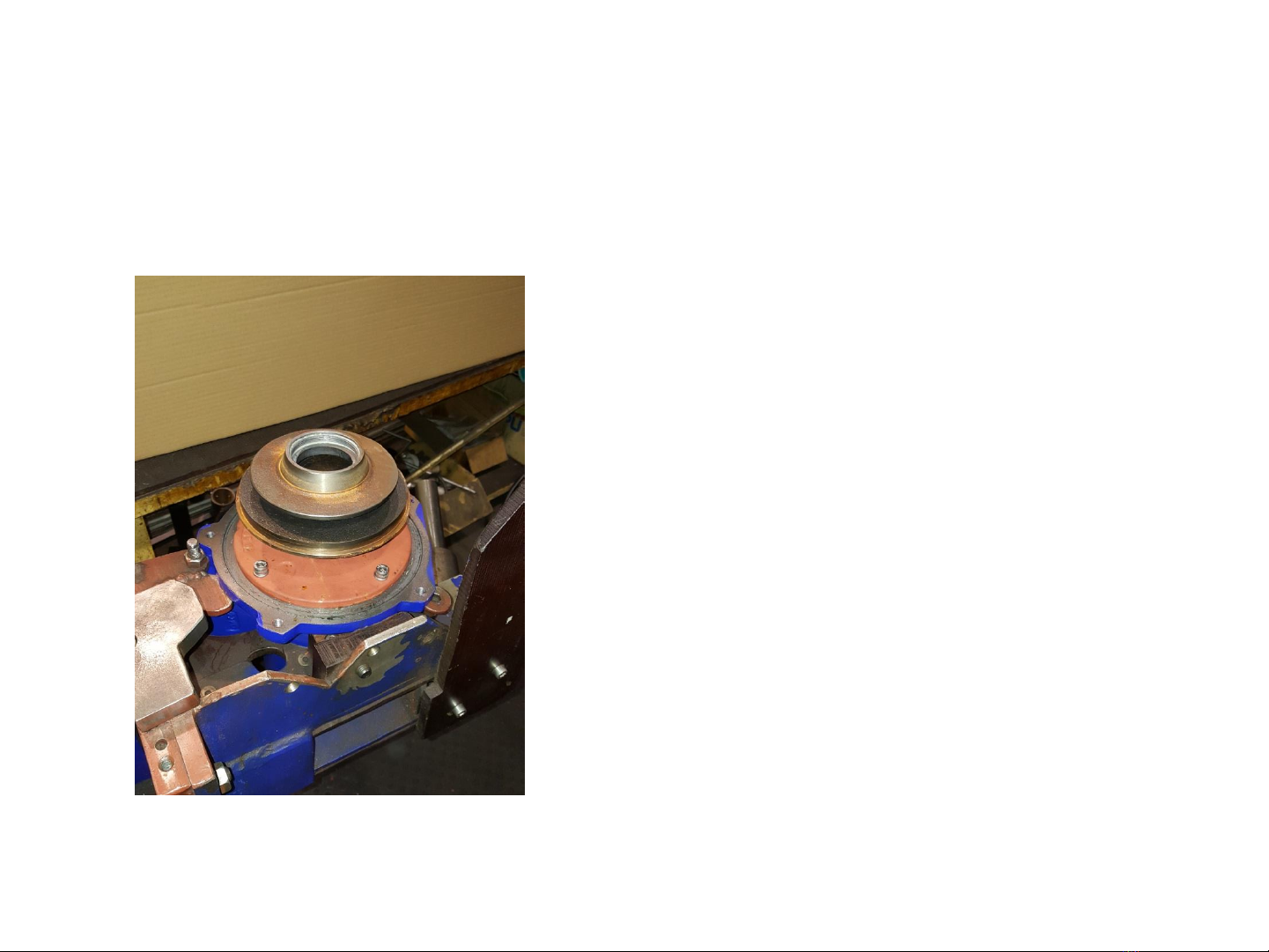
Disassembly of cutting system with
end-face seal at TES 148
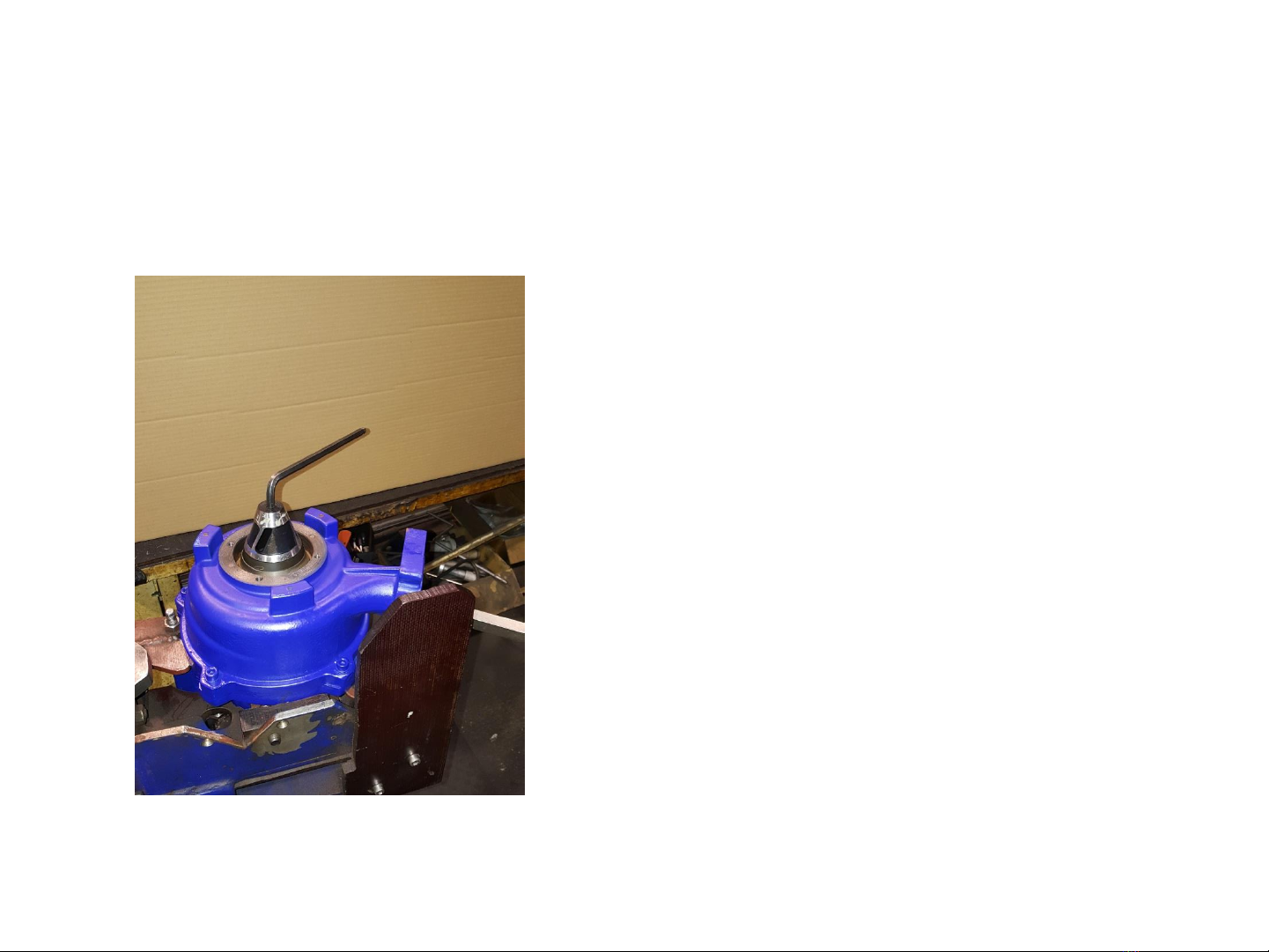
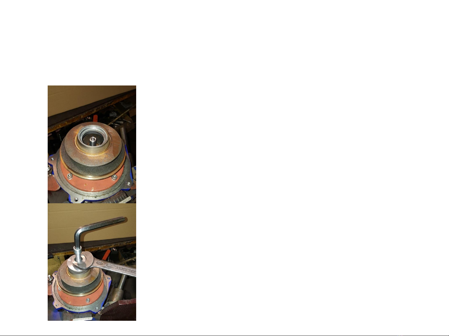
•Loose the cutter with an Allen key 8 mm
•If necessary, hit the cutter with a hammer
(wear protection goggles)
•if the cutter can not yet be loosened, smooth
separation can be caused by heating
•For this purpose heat the cutter evenly in the
area of the impeller
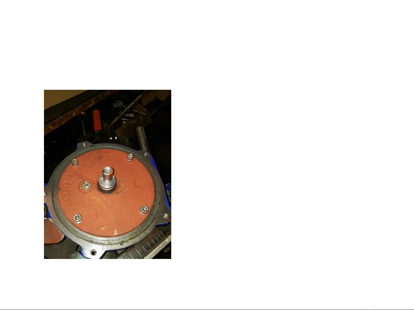
•After heating the cutter can be loosened
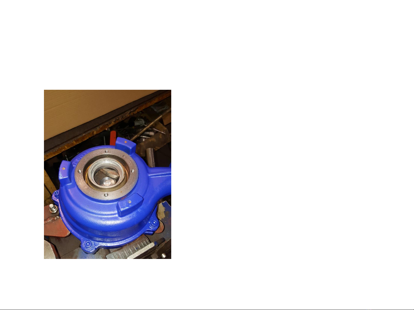
•Allow the cutter to cool down and disassemble
Note:
The more the cutting is worn out the more
complicated is the disassembly
5