CARRARO VARIBULL User manual

I N S T R U C T I O N S
For the installation and maintenance variable area MDM
spring-assisted desuperheaters
IMI0046E.doc
Rev.0 14/03/13
20090 SEGRATE (MI)- via E.Fermi
EMAIL: [email protected]
TEL.(02) 269912.1 - FAX.(02) 2692.2452
Page 1 of 11

I N S T R U C T I O N S
For the installation and maintenance variable area MDM
spring-assisted desuperheaters
IMI0046E.doc
Rev.0 14/03/13
20090 SEGRATE (MI)- via E.Fermi
EMAIL: [email protected]
TEL.(02) 269912.1 - FAX.(02) 2692.2452
Page 2 of 11
CONTENTS
Page
1 General information ............................................................................................3
2 Warranty .............................................................................................................3
3 Scope of these instructions..................................................................................3
4 Safety signs.........................................................................................................4
5 Notice on safety ..................................................................................................5
6 Safety precautions...............................................................................................6
7 Installation………………………………………………………………………………..7
8 Disassembly and assembly…………………………………………………………….9
9 Spring setting……………………………………………………………………………10
10 Removing the packaging..................………………………………………………….11
11 Repairs…………………………………………………………………………………...11

I N S T R U C T I O N S
For the installation and maintenance variable area MDM
spring-assisted desuperheaters
IMI0046E.doc
Rev.0 14/03/13
20090 SEGRATE (MI)- via E.Fermi
EMAIL: [email protected]
TEL.(02) 269912.1 - FAX.(02) 2692.2452
Page 3 of 11
1. GENERAL INFORMATION:
1.1 - RIGHT OF MODIFICATION AND COPYRIGHT
The regulations, standards etc. quoted in these instructions are valid at the time of preparation of this
document and are not subsequently updated. It is the duty of the user to take full responsibility for
applying the most up-to-date version of the standards and regulations in question.
The supplier reserves the right to make changes and technical improvements to data and information
whenever it sees fit to do so. The user shall on no account be entitled to claim a right of modification or
improvement in relation to valves already supplied.
2. WARRANTY
The extent and duration of the warranty are defined in the manufacturer's “General Conditions of Sale”.
The applicable conditions are those stipulated in the most up-to-date version in existence at the time of
delivery.
The warranty does not cover, amongst other cases, damage to valves caused by the following:
°Ignorance of or non-compliance with these instruc tions for use!
°The work of personnel insufficiently qualified to undertake fitting, use or maintenance.
°Normal wear.
°Erroneous or negligent use of the valves.
The warranty shall not be valid and the manufacturer shall accept no responsibility in the event of:
°Non-compliance with regulations for the preventio n of accidents and/or safety standards.
°Imperfect installation, poor commissioning and in correct use.
°Improper or incorrect use, inappropriate applicat ion or work conditions differing from those agreed.
°The user shall bear sole responsibility in the event of physical and/or material damage deriving from
failure to observe the above.
3. SCOPE OF THESE INSTRUCTIONS
These instructions relate to variable area MDM spring-assisted desuperheater

I N S T R U C T I O N S
For the installation and maintenance variable area MDM
spring-assisted desuperheaters
IMI0046E.doc
Rev.0 14/03/13
20090 SEGRATE (MI)- via E.Fermi
EMAIL: [email protected]
TEL.(02) 269912.1 - FAX.(02) 2692.2452
Page 4 of 11
4. SAFETY SIGNS AND WARNINGS SYSTEM
Where appropriate, safety signs appear in the rectangular warning boxes in the margins of this manual.
The rectangular warning boxes are laid out vertically (as shown in the examples below) and consist of
four boxes containing messages highlighting:
- Level of seriousness
- Nature of the risk
- The consequences of interaction with the hazard for personnel or products
- Instructions, if necessary, on how to avoid the hazard
The top box contains a warning word
(DANGER-WARNING-CAUTION-ATTENTION)
, which indicates the
level of seriousness of the risk.
The central box contains a drawing indicating the nature of the hazard and the possible consequences,
for personnel or property, of interaction with the hazard. In some cases of hazards to personnel, the
drawing may suggest what preventive measures can be taken, such as wearing protective clothing, for
example.
The bottom box may contain a message with instructions on how to avoid the hazard. In the case of
hazards to personnel, the message may also contain a more precise definition of the hazard and its
consequences for personnel.
1) DANGER - Immediate hazard, definitely capable of causing serious injury
or death.
2) WARNING - Hazard or hazardous practice that could cause serious injury
or death.
3) CAUTION - Hazard or hazardous practice that could cause mild injury.

I N S T R U C T I O N S
For the installation and maintenance variable area MDM
spring-assisted desuperheaters
IMI0046E.doc
Rev.0 14/03/13
20090 SEGRATE (MI)- via E.Fermi
EMAIL: [email protected]
TEL.(02) 269912.1 - FAX.(02) 2692.2452
Page 5 of 11
5. NOTICE ON SAFETY
Thorough checking and maintenance play a key role in ensuring the safe, reliable operation of all valves.
The service procedures recommended by CARRARO and described in this manual constitute effective
methods for performing the necessary maintenance operations. This service manual contains various
warnings and invitations to take care, which must be read carefully in order to minimise the risk of injury
to personnel and the possibility of adopting incorrect work methods which may damage the valves or
make their operation unsafe. It is also important to note that these warnings can never be exhaustive.
CARRARO is not in a position to know, assess and warn customers or users of all the conceivable
methods with which servicing may be carried out and all the potentially hazardous consequences of such
methods.
CARRARO has not therefore attempted to undertake such a task. Anyone using a service procedure or
tool not recommended by CARRARO must therefore make certain that neither their own safety nor that of
other people, nor the safety or correct operation of the valve is put at risk by the chosen work method.
If in doubt about a given procedure, contact CARRARO for advice.
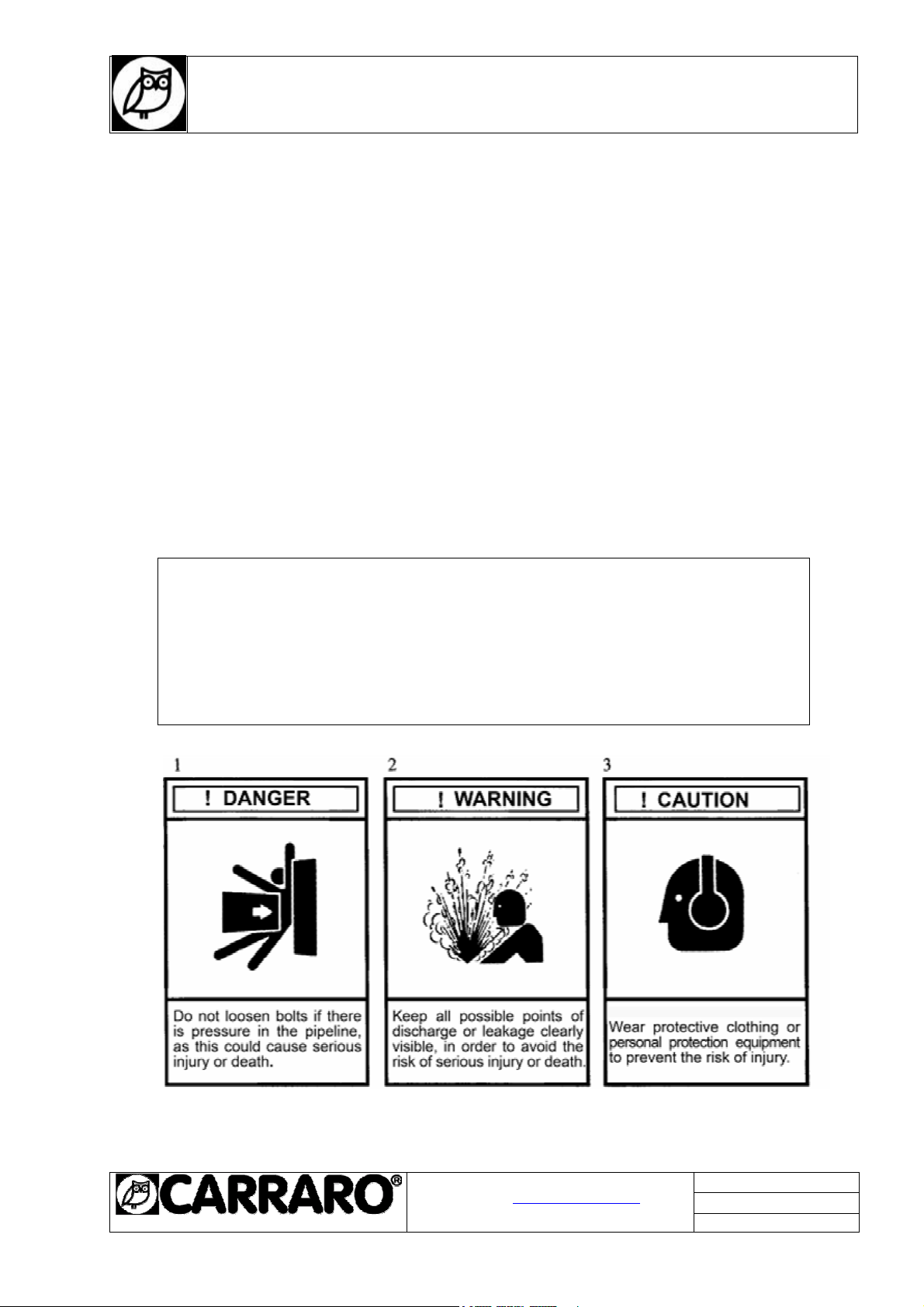
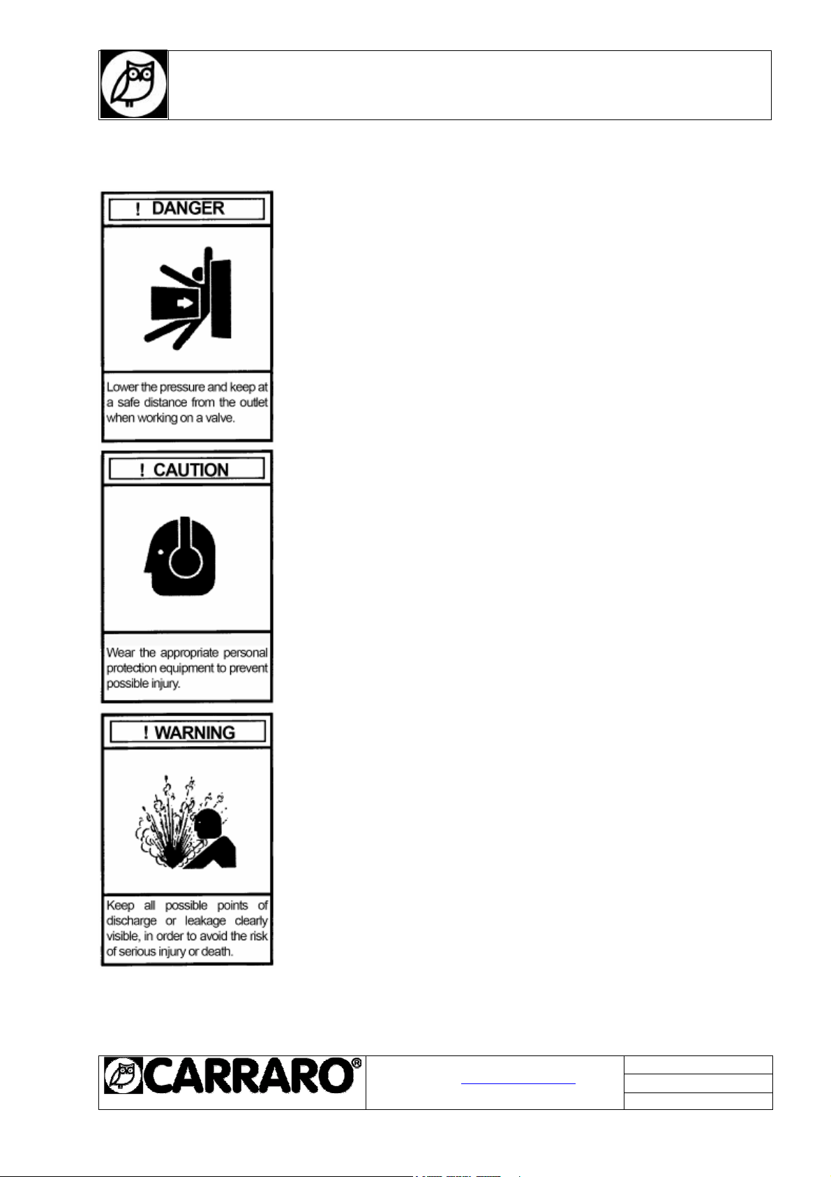
The testing, installation or disassembly of valves or accessories may lead to contact with fluid at high
pressures or temperatures and/or corrosive or erosive fluid, and fluid capable of generating a potentially
explosive atmosphere.
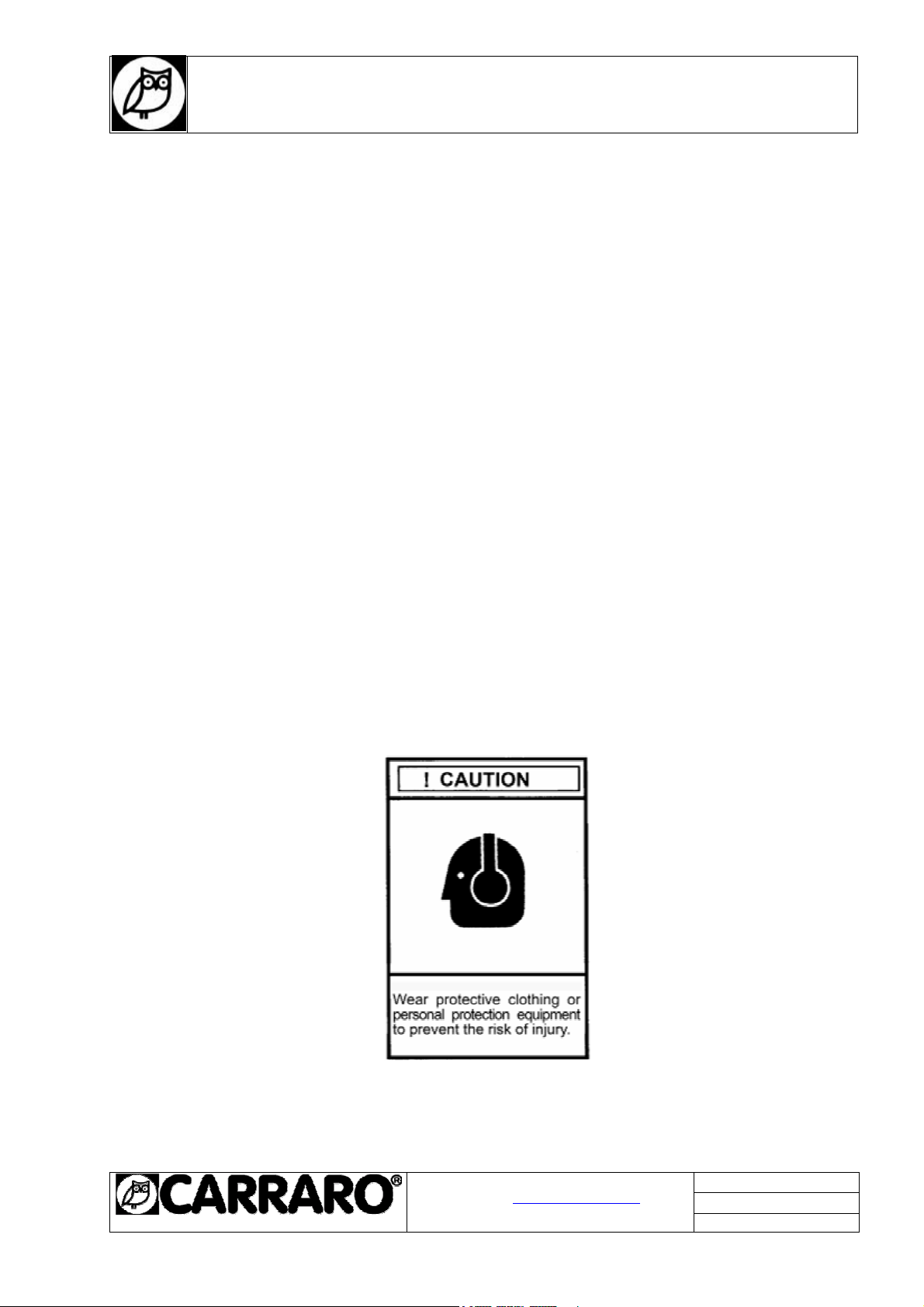
Comprehensive precautions must therefore be taken to prevent injury to personnel during testing,
installation or removal; including, by way of example only: ear defenders, protective goggles, protective
clothing such as gloves, etc., regardless of whether the persons in question are located directly in the
work zone or in the surrounding area.
In view of the widely varying conditions and circumstances that may arise in relation to the operations to
be carried out on products, and of the possible hazardous consequences of the way in which they are
conducted, CARRARO is not in a position to foresee everything that might pose a risk of injury to persons
or damage to property, and can therefore only offer, by way of assistance, this reminder to take care and
a few suggestions (set out below) on safety precautions.
It is the responsibility of the user of CARRARO products to attend to the training of the personnel
assigned to their use.
It is imperative that such personnel acquire a full knowledge of the instructions relating to the product and
of this manual.

I N S T R U C T I O N S
For the installation and maintenance variable area MDM
spring-assisted desuperheaters
IMI0046E.doc
Rev.0 14/03/13
20090 SEGRATE (MI)- via E.Fermi
EMAIL: [email protected]
TEL.(02) 269912.1 - FAX.(02) 2692.2452
Page 6 of 11
6. SAFETY PRECAUTIONS
Always follow the safety regulations applicable to the plant and observe the
following precautions:
° Wear protective clothing. Hot water causes burns and superheated
vapour is invisible.
° When disassembling valves, wear protective clothi ng so as to prevent
exposure to splashes of any process fluid that may be left inside the
valves. Bear in mind that such fluid could generate a potentially explosive
mixture.
Before starting disassembly, make certain that the valve is isolated from
any source of pressure that may exist within the system.
° Carry out checking/maintenance of valves at least once every twelve
months.
°The outer surfaces of valves reach temperatures approximately equal to
the temperature of the fluid flowing through them. For this reason, if fitting
a valve in a potentially explosive atmosphere, check that the explosion
point of the atmosphere surrounding the valve is sufficiently higher than the
temperature of the fluid handled by the system, and prevent deposits of
dust from forming on the outside of the valve.
°In the connection between the valve and line, ensure the equipotentiality
of the system in order to prevent the accumulation of electro-static charges
on the outer surfaces of the plant, which could act as an effective trigger in
a potentially explosive atmosphere.
°Before carrying out any work on valve components, consult CARRARO.

I N S T R U C T I O N S
For the installation and maintenance variable area MDM
spring-assisted desuperheaters
IMI0046E.doc
Rev.0 14/03/13
20090 SEGRATE (MI)- via E.Fermi
EMAIL: [email protected]
TEL.(02) 269912.1 - FAX.(02) 2692.2452
Page 7 of 11
7.
INSTALLATION
Before installation, visually inspect the desuperheater to make certain that they are not damaged. Check
that the information given in the documentation and on the data plate, and the tag number correspond to
the specifications of the order. Remove the desuperheater from its package by lifting it with slings (for
heavy loads) wrapped round its body. Do not remove the flange coverings until immediately before
installation.
During installation of the desuperheater, use gaskets and fasteners which comply with the appropriate
standards.. Before wled to main pipe, for BW solution, or tightening the studs for flanged solution, check
the arrow on the pipe is directed in the same direction as the steam flow.(see Fig.1)
The desuperheater must not be installed in such a way that it is subject to tensions, forces and torque.
The minimum length of tube required downstream varies according to application and is specified in the
respective quote. This length without bends is necessary to prevent erosion caused by drops of water
deposited on the walls of the pipes, the valves and the fittings, and is normally a minimum of 4, 6 m
(a straight length of pipe is not generally necessary upstream). The distance that separates the
desuperheater from the temperature sensor is between 10 and 15 m, although the specific distance for
the application is generally specified in the quote.
Longer distances ensure complete evaporation of the water at lower vapour speeds. The temperature
sensor must be positioned in the top half of the pipe. Avoid fitting branches of the vapour pipe between
the desuperheater and the sensor.(see Fig.1)
The supply water must be clean filtered and of excellent quality (e.g. boiler supply water) and must be at
constant pressure at all times, as specified in the order documents. Each water supply line must be
protected by its own filter with maximum mesh size of 0.1 mm. If closure components are envisaged in the
water supply line, fit a safety valve of approved type. As for the vapour pipe, use gaskets and fasteners
which comply with the codes of the respective pipes. Flush the water supply line before connecting the
mounting flange of the desuperheater .

I N S T R U C T I O N S
For the installation and maintenance variable area MDM
spring-assisted desuperheaters
IMI0046E.doc
Rev.0 14/03/13
20090 SEGRATE (MI)- via E.Fermi
EMAIL: [email protected]
TEL.(02) 269912.1 - FAX.(02) 2692.2452
Page 8 of 11
FIG.1 – SCHEMATIC PLANT
7.1 START-UP
Make certain that all the components are installed correctly. Calibrate the temperature control
unit/transmitter in such a way that it responds automatically to temperature variations.
Heat the main vapour line and open the valve of the water supply line. Check the water pressure in the
desuperheater and the operation of the transmitter and temperature control unit by manually increasing
and reducing the output signal and observing the temperatures shown and recorded. Once there is
satisfactory correspondence between the signals sent by the instruments and the actual temperature, it is
possible to set the regulation point and activate the system in automatic mode.
You are advised to record the various coordinates of the vapour over a sufficiently long period, in order to
check the operation of the system and make the necessary modifications.

I N S T R U C T I O N S
For the installation and maintenance variable area MDM
spring-assisted desuperheaters
IMI0046E.doc
Rev.0 14/03/13
20090 SEGRATE (MI)- via E.Fermi
EMAIL: [email protected]
TEL.(02) 269912.1 - FAX.(02) 2692.2452
Page 9 of 11
8 DISASSEMBLY AND REASSEMBLY
The maintenance of the desuperheater is very simple and requires no special knowledge. It is advisable
to check each year and replacing the nozzle every two years. Before removing from the system the
desuperheater or beginning maintenance in line, check that the steam pipes and water pipe are
completely depressurized , drained and vented .
8.1
DISASSEMBLY MDM (Fig.2)
8.1.1 Remove nuts(3) from body cover(4) and extract the cage (6) from the valve body.
8.1.2 Unfold locking washer (10) and remove the nozzle assembly from the body.
8.1.3 To replace spring (11), remove pin (12), then unscrew nut (13) and remove plug (9) from the nozzle
(8).
FIG. 2 - ASSEMBLY OF VARISPRING WALL MOUNTED TYPE

I N S T R U C T I O N S
For the installation and maintenance variable area MDM
spring-assisted desuperheaters
IMI0046E.doc
Rev.0 14/03/13
20090 SEGRATE (MI)- via E.Fermi
EMAIL: [email protected]
TEL.(02) 269912.1 - FAX.(02) 2692.2452
Page 10 of 11
NUMBER ITEM
1 BODY VALVE
2 STUD
3 NUT
4 BODY COVER
5 GASKET
6 CAGE
7 GASKET
8 NOZZLE
9 PLUG
10 LOCKING WASHER
11 SPRING
12 PIN
13 NUT
9 SPRING SETTING
Insert between nut (13) and nozzle (8) a
spacer as thick as travel value (see Table),
then tighten nut (13) to load the spring.Lock
nut (13) and fasten it by the pin (12). For
reassembly screw the nozzle into the cage,
bend the stop locking washer into the hole
and on the nozzle, change the gaskets,
insert the cage in the body valve and close
it with the cover. Then tighten the nuts(3).

I N S T R U C T I O N S
For the installation and maintenance variable area MDM
spring-assisted desuperheaters
IMI0046E.doc
Rev.0 14/03/13
20090 SEGRATE (MI)- via E.Fermi
EMAIL: [email protected]
TEL.(02) 269912.1 - FAX.(02) 2692.2452
Page 11 of 11
N
OZZLE TYPE
Plug travel
S (mm)
DM 4 0,7
DM8 1,1
DM12 1,2
DM 25 1,5
DM 40 2
DM 65 2,5
10 REMOVING THE PACKAGING
Carraro desuperheaters are packed with the most care in wooden crates or cardboard boxes so that they
are protected during handling and transport to their place of installation. After hydrostatic testing, the
desuperheater is flushed through with an protective agent formulated to protect the internal surfaces
against corrosion. Should any damage occur during transport, however, the transport company or a
representative of Carraro must be notified immediately. Remove the packaging with care, then check that
the surfaces of the flanges, threads, connection pipes, etc. are not damaged.
11 REPAIRS
11.2 If it’s not possible to eliminate the problems, send faulty desuperheater to the
supplier/manufacturer, together with a description of the problem.
11.2 In order to receive spare parts or information, always quote the series number shown on the
rating plate attached to the valve or punched on the outer surface of the flanges. If you have only
the DM the series number is on the nozzle(see 1 fig3).
11.3 To ensure the valves treated in this manual work correctly, they should be serviced by Carraro
engineers or by Carraro-authorised Service Centres using original spare parts.
ATTENTION!
The maker declines all liability for modifications to the product or
operations that are not contemplated in this manual.
Table of contents