REDEX SRP0 User manual

Planetary servo-reducer
SRP
Mounting, Setup and Maintenance
Instructions
Document: RX182/006
Version: 01/2017

Language Summary:
I. English
II. French / Français
III. German / Deutch
IV. Spanish / Español
V. Italian / Italiano
VI. Chinese / 简体中文

SRP User manual
Ref.: RX182/006
Version 01/2017 - English
This document must not be reproduced nor information therein disclosed without our authorization
Page 1/ 28
Summary: English version
1INTRODUCTION 2
1.1 WARNINGS 2
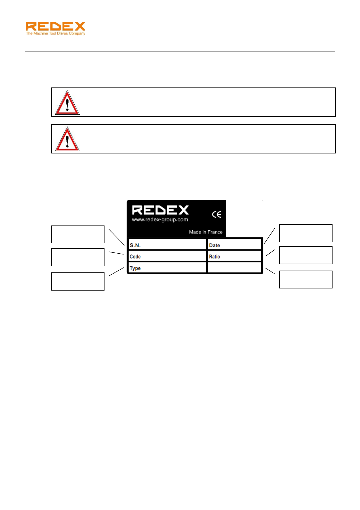
1.2 GEARBOX IDENTIFICATION 2
1.3 LONG TERM STORAGE 2
2TECHNICAL DATA 3
2.1 GEARBOX 3
2.2 OUTPUT PINION 3
2.3 MOUNTING POSITION NOMENCLATURE 3
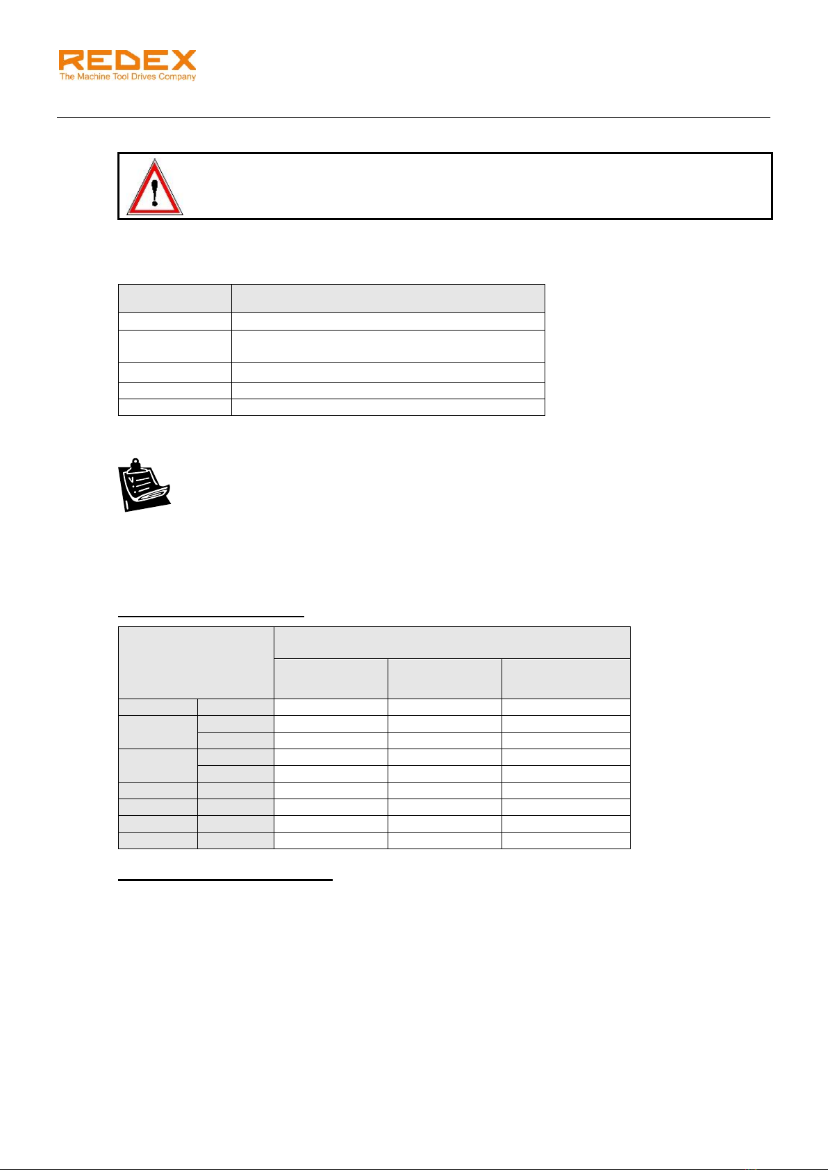
3LUBRICATION 4
3.1 RECOMMENDED LUBRICANTS 4
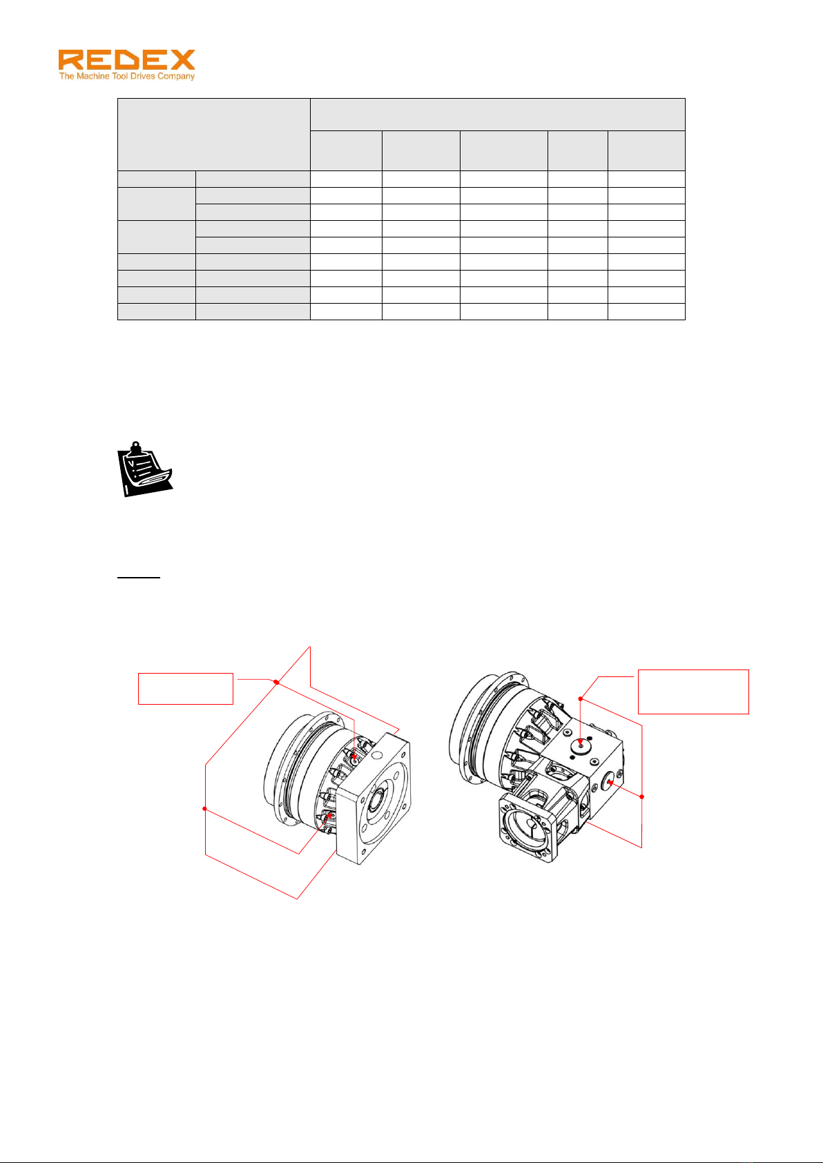
3.2 OIL FILLING 4
3.3 OIL DRAINING 5
4MOTOR INSTALLATION 8
4.1 MF-TYPE MOTOR FLANGE MOUNTING (FOR RIGHT ANGLE CONFIGURATIONS SRP.R AND CYLINDRICAL SHAFTS) 8
4.2 MF-TYPE MOTOR FLANGE MOUNTING (FOR RIGHT ANGLE CONFIGURATIONS SRP.R AND TAPER SHAFTS) 10
4.3 IF-TYPE MOTOR FLANGE MOUNTING (FOR IN-LINE CONFIGURATIONS SRP.M) 11
5OUTPUT PINION (OP) MOUNTING 14
6MOUNTING OF THE SRP ON THE MACHINE FRAME 15
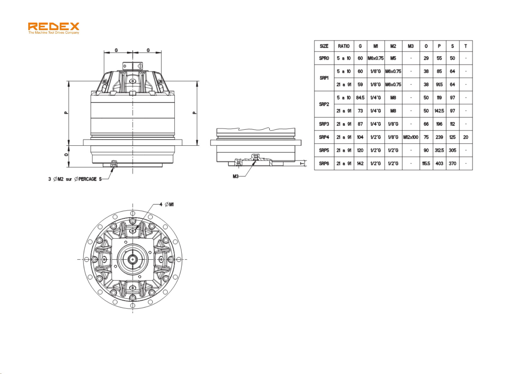
6.1 GEARBOX FIXING FLANGE DETAILS 15
6.2 OUTPUT FLANGE CONNECTION 16
7MOUNTING OF THE SRP WITH OUTPUT PINION ON THE MACHINE 17
7.1 RACK MOUNTING TOLERANCE 17
7.2 SRP PARALLELISM AND PERPENDICULARITY TOLERANCES 18
7.3 SRP MOUNTING HEIGHT SETTING 19
7.4 PROPER TOOTH MESHING VALIDATION 20
7.5 TOOTH CONTACT PATTERN CHECK 21
8SRP WITH MECHANICAL PRELOAD 22
8.1 DESCRIPTION 22
8.2 SHAFT ALIGNMENT 23
8.3 GANTRY MACHINE CONFIGURATION 24
8.4 PRELOAD SETTING –LINEAR DRIVE 25
8.5 PRELOAD SETTING –ROTARY DRIVE 27
9RACK & PINION LUBRICATION: OPTIONAL LUBE PINION (PGRP) AND LUBE PINION SUPPORT (SURP)
28
9.1 DESCRIPTION OF THE PGRP &SURP OPTION 28
9.2 RECOMMENDED LUBRICANTS 28
9.3 OIL FLOW RATES 28

SRP User manual
Ref.: RX182/006
Version 01/2017 - English
This document must not be reproduced nor information therein disclosed without our authorization
Page 2/ 28
1 INTRODUCTION
The SRP planetary gearbox will give you complete satisfaction if all of the following mounting, operating &
maintenance instructions are respected.
1.1 Warnings
WARNING! HANDLING OPERATIONS.
The SRP unit can be handled by the main housing, the bevel box shafts, the fixing flange
holes or, with lifting rings by the output flange tapped holes.
WARNING! LUBRICATION REQUIREMENTS.
SRP units are delivered with oil and lubricated for a life time of 10000 hours.
Refer to lubrication chapter in this manual to respect all lubrication requirements.
Any damage due to an incorrect lubrication will void the warranty.
1.2 Gearbox identification
Each unit can be identified through its identification plate and the serial number indicated on it. The serial
number must be given for any correspondence on a particular unit.
1.3 Long term storage
Each gearbox is delivered wrapped and greased for 1 month anti-corrosion protection. Gearboxes which
are not installed shortly after receipt should be stored in a dry atmosphere with temperature between 0°C
& 40°C. The unit must be filled completely with oil for storage.
Serial number
Drawing code
Designation
Shipment date
Reduction ratio
Backlash (if
needed)
861606
RX128656-12
SRP1.M.91.3.B5
NOV. 2016
91

SRP User manual
Ref.: RX182/006
Version 01/2017 - English
This document must not be reproduced nor information therein disclosed without our authorization
Page 3/ 28
2 TECHNICAL DATA
2.1 Gearbox
SRP0
SRP1
SRP2
SRP3
SRP4
SRP5
SRP6
Maximum
acceleration
output torque
(Nm)
1 stage
i=5
350
648
1750
-
-
-
-
i=7
350
665
1750
-
-
-
-
i=10
350
473
1400
-
-
-
-
2 stages
i=17
-
683
1838
3238
6125
-
-
i=21
-
534
1400
2625
6125
7520
16585
i=31
-
753
2100
3850
6300
10050
18590
i=46
-
473
1400
2468
4480
8800
17128
i=61
-
656
2013
2695
4970
8800
13330
i=91
-
473
1400
2695
4970
8800
17128
Max. input
speed (rpm)
1 stage
i=5, 7, 10
6000
5000
4000
-
-
-
-
2 stages
i=21 to 91
-
6000
6000
5000
4000
4000
3500
Approx.
Weight (kg)
SRP.R
1 stage
11.3
18.3
41.2
-
-
-
-
2 stages
-
17
40.2
83.5
144
530
635
SRP.M
1 stage
6.8
13.8
33.7
-
-
-
-
2 stages
-
14.9
35.7
76.0
123
238
510
2.2 Output pinion
The SRP unit can be delivered with an output pinion fixed on the output flange. The pinion has the
following characteristics.
OP 0
OP1
OP2
OP3
OP4
OP5
OP6
Z
45
36
42
35
52
39
45
36
42
35
15
16
14
15
Mo
2
2.5
2.5
3
3
4
4
5
5
6
8
8
10
10
D02
95.49
111.41
165.52
190.99
222.82
128
127.32
150
148.54
b0
19°31’42”
0°
19°31’42”
0°
19°31’42”
Note:
Data are subjected to change without prior notices.
2.3 Mounting position nomenclature
Output flange position / motor flange position (if different) with:
- B5 horizontal
- V1 vertical down
- V3 vertical up
Examples:
V1/B5: output flange vertical down / motor flange horizontal
B5: output flange & motor flange horizontal

SRP User manual
Ref.: RX182/006
Version 01/2017 - English
This document must not be reproduced nor information therein disclosed without our authorization
Page 4/ 28
3 LUBRICATION
3.1 Recommended lubricants
WARNING!
SRP units are delivered with oil and lubricated for a life time of 10000 hours.
Any damage to the unit due to an improper lubrication, quantity or quality, will void the
warranty.
We recommend using a synthetic PAO based oil with viscosity 150 Cst at 40°C to lubricate the SRP such
as one of the followings (or an equivalent); for alternates, please consult us.
Trade mark
Oil reference
KLUBER
KLUBERSYNTH EG4-150
MOBIL
MOBILGEAR SHC XMP 150 or
MOBIL SHC629 (warning: life time 7500 hours)
TOTAL
CARTER SH150
SHELL
OMALA HD150
LUBCON
TURMOSYNTHOIL 150
3.2 Oil filling
1. Unscrew the oil fill-in plug situated on the upper side of the unit.
2. Fill the unit until oil comes out of the level hole (approximated oil quantity is given in the following
tables).
3. Replace the oil fill-in plug.
3.2.1 SRP.M: in-line configuration
Approximated volume of oil (cm3) depending of
mounting position
B5
V1
V3
SRP0
1 stage
100
165
165
SRP1
1 stage
165
320
240
2 stages
190
350
300
SRP2
1 stage
530
1100
900
2 stages
600
1200
1123
SRP3
2 stages
1200
2100
1700
SRP4
2 stages
1450
3100
3000
SRP5
2 stages
3400
6300
6600
SRP6
2 stages
6600
11850
12750
3.2.2 SRP.R: right angle configuration
Check that the oil level reaches the middle of the sight-glass. Please note that the level on the sight glass
may take some time to stabilize.

SRP User manual
Ref.: RX182/006
Version 01/2017 - English
This document must not be reproduced nor information therein disclosed without our authorization
Page 5/ 28
SRP.R: right angle
configuration
Approximated volume of oil (cm3) depending of
mounting position
B5/B5
V1/B5
V3/B5
B5/V1
B5/V3
SRP0.R
1 stage
330
400
600
330
330
SRP1.R
1 stage
640
800
1200
650
650
2 stages
370
550
680
380
380
SRP2.R
1 stage
1500
2100
2200
1480
1480
2 stages
900
1500
1500
880
880
SRP3.R
2 stages
1650
2700
2900
1600
1600
SRP4.R
2 stages
2600
4100
4700
2600
2600
SRP5.R
2 stages
5600
8500
1400
5400
5400
SRP6.R
2 stages
15200
18200
Consult us
15200
15200
3.3 Oil draining
SRP units are delivered with oil and lubricated for a life time of 10000 hours.
In order to remove all residual particles in oil, do not hesitate to:
- Run the unit before draining in order to reduce the viscosity of the old lubricant
- “Wash” the unit with fresh oil before refilling.
1. Unscrew the fill-in plug situated at the top of the unit to allow air entering the gearbox.
2. Unscrew the lowest plugs and wait until no more oil flows out from the unit.
NOTE:
Drained oil is a special industrial waste and should be handled according to current laws.
Location of oil plugs and sight glass:
SRP.M
SRP.R
The following drawings show the exact location of the lubrication holes (for size 5 and 6, consult us):
4 symmetrical
lubrication plugs
3 symmetrical
lubrication plugs
+ 1 sight glass

SRP User manual
Ref.: RX182/006
Version 01/2017 - English
This document must not be reproduced nor information therein disclosed without our authorization
Page 6/ 28

SRP User manual
Ref.: RX182/006
Version 01/2017 - English
This document must not be reproduced nor information therein disclosed without our authorization
Page 7/ 28

SRP - User manual
Ref.: RX182/006
Version 01/2017 - English
This document must not be reproduced nor information therein disclosed without our authorization
Page 8 / 28
Coupling
Shaft adapter
4 MOTOR INSTALLATION
4.1 MF-type motor flange mounting (for right angle configurations SRP.R and cylindrical shafts)
Respect the following instructions to install the motor flange.
1. Clean the mounting surfaces to be fitted together i.e.: coupling, pilot diameter of the motor, the flange
and the motor shaft.
2. Mount the coupling (with or without shaft adapter) onto the bevel box shaft.
WARNING!
When the coupling bore is bigger than the diameters of the motor shaft or bevel box shaft, a
shaft adapter is supplied with the coupling. The groove of this adapter must be aligned with
the coupling split bore.
3. Place the coupling with respect of the distance A (see picture & table).
4. Tighten the screw of the coupling on the bevel box side (adequate tightening torque: see table 1).
5. Mount the MF flange and tighten its 4 fixing screws (“screws MF Bevel box & torque” in table 1).
6. Carefully slide the motor shaft into the coupling bore (with the shaft adapter if supplied) until the motor
face sits in the pilot diameter bore of the MF flange.
7. Tighten the motor screws one after the other in several passes (see tightening torque in table 2).
8. Tighten the other screw of the coupling (at the adequate tightening torque: see table 1).
Screws MF --> Bevel box
Screws of
the motor
flange
MF
Screw of the
coupling
Distance A

SRP - User manual
Ref.: RX182/006
Version 01/2017 - English
This document must not be reproduced nor information therein disclosed without our authorization
Page 9 / 28
Table 1: screws and distance A
Size
Ratio
MF type
Screws MF --> Bevel
box & torque
Screws of the
coupling & torque
Dist.
A (+/-1mm)
SRP0.R
5;7;10
MF2N
M6 –17 Nm
M10 –50 Nm
60
SRP1.R
5;7;10
MF3N
M8 –41Nm
M10 –50Nm
60
21;31;46;61;91
MF1N
M5 –10Nm
M8 –40Nm
65
SRP2.R
5;7
MF4R
M10 –83Nm
M12 –120Nm
79
10
MF4N
M12 –110Nm
21;31;46;61;91
MF2N
M6 –17Nm
M10 –50Nm
60
SRP3.R
21;31
MF3R
M8 –41Nm
M12 –110Nm
60
46;61;91
MF3N
M10 –50Nm
SRP4.R
21;31
MF4R
M10 –83Nm
M12 –110Nm
79
46;61;91
MF4N
M12 –120Nm
SRP5.R
21;31;46;61;91
MF5N
M12 –145Nm
M12 –120Nm
60
21;31;46;61;91
MFRP5
-
SRP6.R
21;31;46;61;91
MFRP6
M16 –355Nm
M16 –180Nm
-
Table 2: screws of the motor flange
Screw type
Tightening torque (Nm)
M6
10
M8
25
M10
49
M12
86
M14
135
M16
210

SRP - User manual
Ref.: RX182/006
Version 01/2017 - English
This document must not be reproduced nor information therein disclosed without our authorization
Page 10 / 28
4.2 MF-type motor flange mounting (for right angle configurations SRP.R and taper shafts)
Respect the following instructions to install the motor flange.
1. Clean the mounting surfaces to be fitted together i.e.: coupling, pilot diameter of the motor, the flange
and the motor shaft.
2. Mount the MF flange onto the gearbox and tighten its 4 fixing screws (“screws MF Bevel box &
torque” in table 1).
3. Remove the taper hub part from the coupling.
4. Place the taper hub onto the motor shaft. Tighten the motor shaft nut.
5. Install the coupling on the taper hub part. Tighten the fixing screws (size M6, tightening torque
15Nm).
6. Carefully slide the motor together with the coupling onto the bevel box shaft until the motor face sits in
the pilot diameter bore of the MF flange.
7. Tighten the motor screws one after the other in several passes (see tightening torque in table 2)
8. Tighten the other screw of the coupling (at the adequate tightening torque: see table 1).
Screw of the
coupling
MF
Bevel gearbox
shaft
Taper hub part
8 fixing screws

SRP - User manual
Ref.: RX182/006
Version 01/2017 - English
This document must not be reproduced nor information therein disclosed without our authorization
Page 11 / 28
4.3 IF-type motor flange mounting (for in-line configurations SRP.M)
Respect the following instructions to install the motor flange.
1. Clean the mounting surfaces to be fitted together. Pay special attention to the motor shaft and the
gearbox input split bore.
2. Rotate the clamping hub in order to bring the screws in front of their radial holes. Rotate the input
split-bore of the gearbox in order to align the split bore groove with the clamping hub groove as
shown in the sketch below.
a. In case of a cylindrical shaft
When the clamping hub bore is bigger than the
diameter of the motor shaft, a shaft adapter is
supplied with the unit. The groove of this
adapter must be aligned with the split bore.
b. In case of a taper shaft
A shaft adapter (taper -> cylindrical) is
supplied with the unit. Tighten the motor shaft
nut after installing the adapter.
Surfaces to be cleaned
Clamping hub
Motor flange
Gearbox input
split-bore
Clamping
screws
Clamping
screws hole
Adapter
Clamping hub
Adapter

SRP - User manual
Ref.: RX182/006
Version 01/2017 - English
This document must not be reproduced nor information therein disclosed without our authorization
Page 12 / 28
3. Check that the motor / gearbox interface dimensions are correct. Avoid the following improper
assemblies:
Motor shaft should
not reach the end of
the input bore.
Motor shoulder must
not reach the
clamping hub.
Motor radius must not
reach the clamping
hub.
Motor shaft must be
locked on the full
clamping hub width.
4. Make sure that the clamping screws of the input split-bore are not tight.
5. For size 6 only, install the 2 keys into the appropriate grooves to prevent the input bore from moving
down while mounting the motor. See pictures:
6. Lower the motor vertically onto the gearbox (and for size 6: maintain the 2 additional keys in
position) and fix it by tightening the 4 screws of the flange at the adequate tightening torque (table
below):
WARNING!
The motor must be mounted without applying any stress on the input shaft. The motor
centering is done by the gearbox input shaft. That is why it is absolutely necessary to mount
the motor vertically. A wrong mounting can lead to bad running conditions damageable for
the gearbox.
7. Gradually tighten the 2 clamping hub screws by half rotations until the tightening torque shown in the
table below is reached.
Screws of the motor flange
Screw type
Tightening torque (Nm)
M6
10
M8
25
M10
49
M12
86
M14
135
M16
210
M18
290

SRP - User manual
Ref.: RX182/006
Version 01/2017 - English
This document must not be reproduced nor information therein disclosed without our authorization
Page 13 / 28
Gearbox
type
Motor flange
type
Motor shaft diameter
Screw type
(clamping hub)
Clamping
torque
Min.
Max.
SRP0M
IFA
11 mm
19 mm
2 x M5
10 Nm
22 mm
32 mm
2 x M8
41 Nm
SRP1M
IFB
14 mm
24 mm
2 x M8
41 Nm
28 mm
38 mm
2 x M10
83 Nm
IFA
11 mm
19 mm
2 x M5
10 Nm
22 mm
32 mm
2 x M8
41 Nm
SRP2M
IFC
22 mm
32 mm
2 x M8
41 Nm
35 mm
48 mm
2 x M10
83 Nm
IFB
14 mm
24 mm
2 x M8
41 Nm
28 mm
38 mm
2 x M10
83 Nm
SRP3M
IFB
14 mm
24 mm
2 x M8
41 Nm
28 mm
38 mm
2 x M10
83 Nm
42 mm
2 x M10
83 Nm
IFD
55 mm
65 mm
2 x M12
145 Nm
SRP4M
IFC
22 mm
32 mm
2 x M8
41 Nm
35 mm
48 mm
2 x M10
83 Nm
IFD
55 mm
65 mm
2 x M12
145 Nm
SRP5M
IFC
22 mm
32 mm
2 x M8
41 Nm
35 mm
48 mm
2 x M10
83 Nm
IFD
55 mm
65 mm
2 x M12
145 Nm
SRP6M
IFD
48 mm
55 mm
2 x M12
145 Nm
60 mm
75 mm
2 x M16
355 Nm
WARNING!
It is very important to respect the upper procedure (especially points 4, 5 and 6) in order to
avoid any damage on the gearbox and to insure a proper mounting.
NOTE:
If the input flange needs to be dismounted, the following table gives the tightening torque of the screws
connecting the flange to the gearbox.
Gearbox
type
Motor
flange
type
Screw
class
Screw type &
tightening
torque
SRP0M
IFA
8.8
M6 - 10Nm
SRP1M
IFB
M8 - 25Nm
IFA
M6 - 10Nm
SRP2M
IFC
M10 - 49Nm
IFB
M8 - 25Nm
SRP3M
IFB
M8 - 25Nm
IFD
M14 - 135Nm
SRP4M
IFC
M10 - 49Nm
IFD
M14 - 135Nm
SRP5M
IFC
M10 - 49Nm
IFD
M14 - 135Nm
SRP6M
IFD
M14 - 135Nm

SRP - User manual
Ref.: RX182/006
Version 01/2017 - English
This document must not be reproduced nor information therein disclosed without our authorization
Page 14 / 28
5 OUTPUT PINION (OP) MOUNTING
WARNING!
The rack and the output gears must be lubricated before running the SRP.
In case of fixing an output pinion (OP) to the SRP output flange,
we recommend respecting the following procedure:
1. Place the output pinion on the output flange pilot diameter.
2. Insert the fixing screws without tightening them.
3. Control the pinion run out by means of pins. The admissible
run out values are written in the following table. For other
pinion types, please consult us.
4. Adjust the pinion centering if necessary.
5. Tighten the fixing screws at the adequate tightening torque.
SIZE
Pinion
number
of teeth
Module
(mm)
Pitch
diameter
(mm)
Maximum
Run Out
(Quality
6)
(µm)
Pin diameter
for run out
control
(mm)
OP mounting on SRP
Fixing
screws type
Tightening
torque
(Nm)
0
45
2
95,49
21
3,5
M6
17
36
2,5
21
4,5
1
42
2,5
111,41
21
4,5
M8
41
35
3
21
5
2
52
3
165,52
28
5
M10
83
39
4
29
7
3
45
4
190,99
29
7
M16
355
36
5
29
9
4
42
5
222,82
29
9
M20
690
35
6
29
10
For sizes 5 and 6, the pinion is delivered by Redex mounted and adjusted on the SRP. The customer
shall not adjust or change any parameter.

SRP - User manual
Ref.: RX182/006
Version 01/2017 - English
This document must not be reproduced nor information therein disclosed without our authorization
Page 15 / 28
6 MOUNTING OF THE SRP ON THE MACHINE FRAME
WARNING! HANDLING OPERATIONS.
The SRP unit can be handled by the main housing, the bevel box shafts, the fixing flange
holes or, with lifting rings by the output flange tapped holes.
First of all, clean the mounting surfaces to be fitted together: gearbox flange, pilot diameter, machine
surface, driven part on output.
6.1 Gearbox fixing flange details
Size
n1 x D3c
Recommended
fixing screws
Tightening torque
(Nm)
SRP0
8 x 5,5
M5 class 12.9
10
SRP1
12 x 6,5
M6 class 12.9
17
SRP2
12 x 9
M8 class 12.9
41
SRP3
16 x 13,5
M12 class 12.9
145
SRP4
SRP5
12 x 17,5
M16 class 12.9
355
SRP6
12 x 22
M20 class 12.9
690
6.1.1 Output side fixing
The gearbox can be fixed from the output side using the pilot diameter D2d.
Size
Pilot diameter
D2d (mm)
SRP0
110h7
SRP1
140h7
SRP2
200h7
SRP3
255h7
SRP4
285h7
SRP5
355j6
SRP6
450j6
6.1.2 Input side fixing
The gearbox can be fixed from the input side using the pilot diameter D1c. This also allows sealing the
output side if needed.
Size
O-ring seal dim.
Pilot diameter D1c
(mm)
SRP0
108 to 113
120h7
SRP1
138 to 145
152h7
SRP2
192 to 200
212h7
SRP3
232 to 242
255h7
SRP4
259 to 270
285h7
SRP5
N/A
355j6
SRP6
N/A
450j6
n1 x D3c

SRP - User manual
Ref.: RX182/006
Version 01/2017 - English
This document must not be reproduced nor information therein disclosed without our authorization
Page 16 / 28
6.2 Output flange connection
6.2.1 Size 0, 1, 2, 3, 4
Size
Nbr of screws x D2f
(class 12.9)
Tightening
torque
(Nm)
Pinning
hole
SRP0
15 x M6
17
1 x 7 mm
SRP1
11 x M8
41
1 x 8 mm
SRP2
11 x M10
83
1 x 10 mm
SRP3
3 x 4 x M16
355
-
SRP4
3 x 4 x M20
690
-
NOTE:
For units with size 0, 1 & 2, we recommend pining the accessory on gearbox output according to
ISO9409 norm recommendations.
6.2.2 Size 5 and 6
Size
A
B
C
D
E
F
Nbr of screws x D2f (class 12.9)
SRP5
112H6
99H6
10
46
8
97
5 x M16x30 at 72° on Ø68.5
SRP6
132H6
115H6
12
53
10
112
5 x M20x35 at 60° on Ø 87

SRP - User manual
Ref.: RX182/006
Version 01/2017 - English
This document must not be reproduced nor information therein disclosed without our authorization
Page 17 / 28
7 MOUNTING OF THE SRP WITH OUTPUT PINION ON THE MACHINE
WARNING! HANDLING OPERATIONS.
The SRP unit can be handled by the main housing, the bevel box shafts, or, with lifting
rings by the output flange tapped holes.
7.1 Rack mounting tolerance
Parallelism between the rack reference surface and the linear guide
The SRP requires that the rack has been installed on the machine following the rack manufacturer
mounting procedure and respects the tolerances shown below:
We advice to measure the parallelism error values on 3 points for each segment of rack, as shown on the
drawing below. This rack topography will be used for proper tooth meshing validation and preload
setting (see next chapters).
In order to control the pitch error, we also recommend doing 3 measurements at each connection of 2
rack segments, as shown on the sketch below.
The variation between the 3 comparators at each connection must not exceed:
- 0.015 mm for a rack module 3,
- 0.020mm for a rack module > 3.
Size
Pinion
module
(mm)
Maximum parallelism error
between rack & linear guide
Pin
diameter
to use
For 1
section
of rack
(mm)
For
complete
axis length
(mm)
0
2
4
0,015
0,04
2,5
5 0,015 0,04
1
2,5
3
6 0,02 0,05
2
3
4
8 0,02 0,05
3
4
5
10 0,02 0,05
4
5
6
12
0,04
0,07
5
8
16
0,06
0,08
6
10
20
0,06
0,08

SRP - User manual
Ref.: RX182/006
Version 01/2017 - English
This document must not be reproduced nor information therein disclosed without our authorization
Page 18 / 28
7.2 SRP parallelism and perpendicularity tolerances
Parallelism between the SRP flange and the rack axis
Size
Maximum allowed mounting
tolerances
y:
parallelism of flange fixing face with
rack main axis
0
0,02 mm
1
0,02 mm
2
0,02 mm
3
0,02 mm
4
0,025 mm
5
0,030 mm
6
0,030 mm
This manual suits for next models
6
Table of contents
Languages:
Other REDEX Industrial Equipment manuals