–
®
ORTEC
®
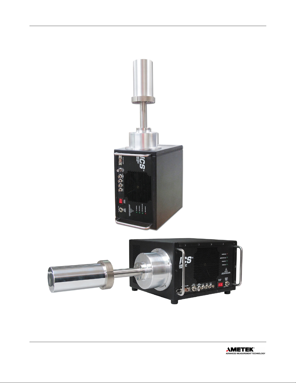
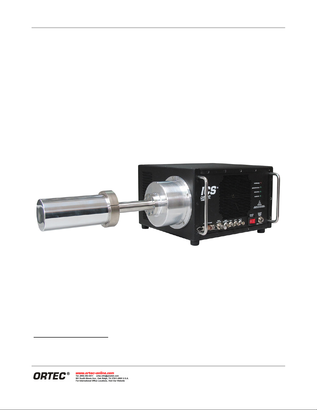
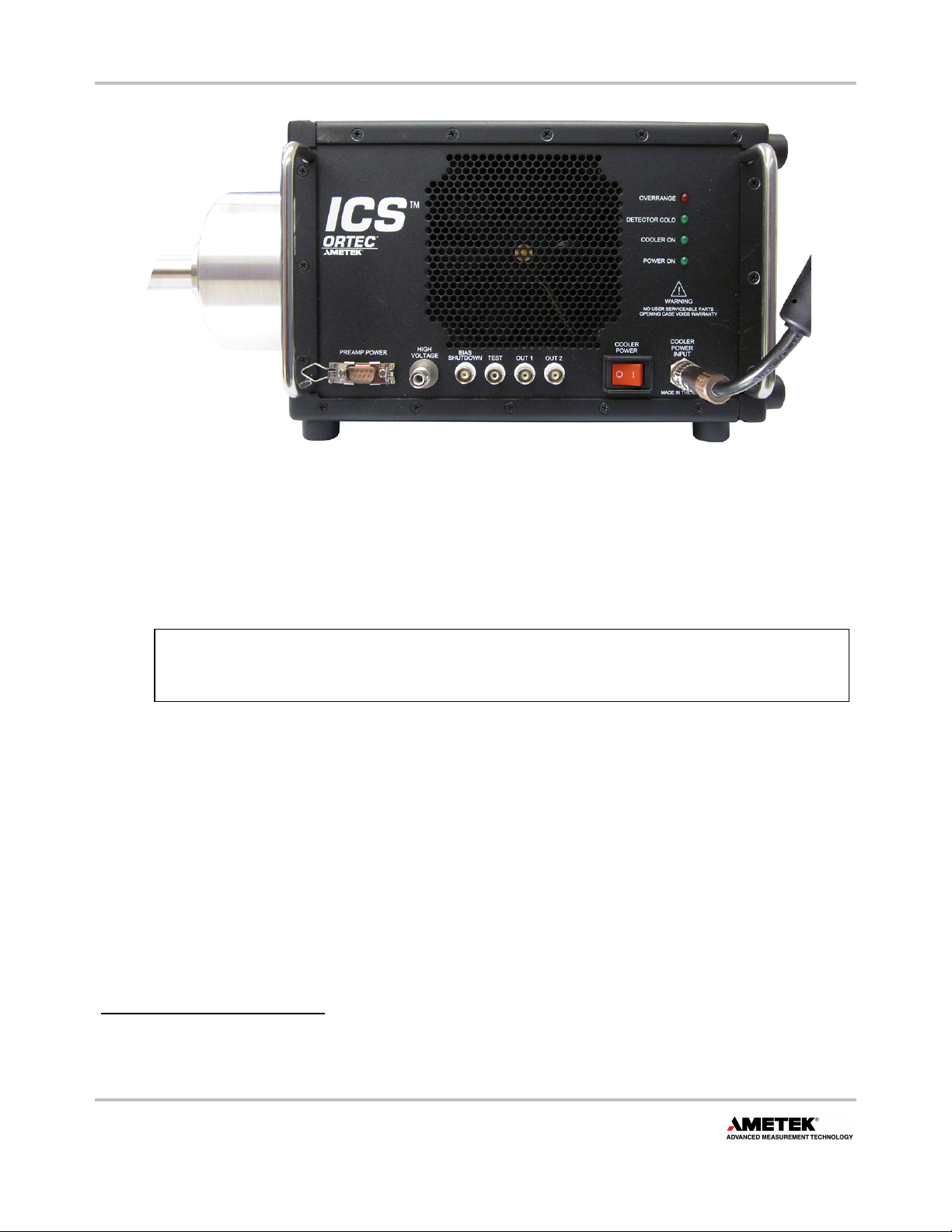
ICS™ Integrated Cryocooling System 806281B / 0315
ii
Advanced Measurement Technology, Inc.
(“AMT”)
WARRANTY
AMT warrants that the items will be deli ered free from defects in material or workmanship. AMT makes no other
warranties, express or implied, and specifically NO WARRANTY OF MERCHANTABILITY OR FITNESS FOR A PARTICULAR
PURPOSE.
AMT’s exclusi e liability is limited to repairing or replacing at AMT’s option, items found by AMT to be defecti e in
workmanship or materials within one year from the date of deli ery with the exception of the cryocooler, internal controller,
and acti e noise cancellation, which are warranted for two years. AMT’s liability on any claim of any kind, including
negligence, loss, or damages arising out of, connected with, or from the performance or breach thereof, or from the
manufacture, sale, deli ery, resale, repair, or use of any item or ser ices co ered by this agreement or purchase order, shall
in no case exceed the price allocable to the item or ser ice furnished or any part thereof that gi es rise to the claim. In the
e ent AMT fails to manufacture or deli er items called for in this agreement or purchase order, AMT’s exclusi e liability and
buyer’s exclusi e remedy shall be release of the buyer from the obligation to pay the purchase price. In no e ent shall AMT
be liable for special or consequential damages.
Quality Control
Before being appro ed for shipment, each AMT instrument must pass a stringent set of quality control tests designed to
expose any flaws in materials or workmanship. Permanent records of these tests are maintained for use in warranty repair
and as a source of statistical information for design impro ements.
Repair Service
If it becomes necessary to return this instrument for repair, it is essential that Customer Ser ices be contacted in ad ance of
its return so that a Return Authorization Number can be assigned to the unit. Also, AMT must be informed, either in writing,
by telephone [(865) 482-4411] or by facsimile transmission [(865) 483-2133], of the nature of the fault of the instrument
being returned and of the model, serial, and re ision (“Re ” on rear panel) numbers. Failure to do so may cause unnecessary
delays in getting the unit repaired. The AMT standard procedure requires that instruments returned for repair pass the same
quality control tests that are used for new-production instruments. Instruments that are returned should be packed so that
they will withstand normal transit handling and must be shipped PREPAID ia Air Parcel Post or United Parcel Ser ice to the
designated AMT repair center. The address label and the package should include the Return Authorization Number assigned.
Instruments being returned that are damaged in transit due to inadequate packing will be repaired at the sender's expense,
and it will be the sender's responsibility to make claim with the shipper. Instruments not in warranty should follow the same
procedure and AMT will pro ide a quotation.
Damage in Transit
Shipments should be examined immediately upon receipt for e idence of external or concealed damage. The carrier making
deli ery should be notified immediately of any such damage, since the carrier is normally liable for damage in shipment.
Packing materials, waybills, and other such documentation should be preser ed in order to establish claims. After such
notification to the carrier, please notify AMT of the circumstances so that assistance can be pro ided in making damage
claims and in pro iding replacement equipment, if necessary.
Copyright © 2015, Ad anced Measurement Technology, Inc. All rights reser ed.
ORTEC® is a registered trademark of Ad anced Measurement Technology, Inc. All other trademarks used herein are the property of their
respecti e owners.
NOTICE OF PROPRIETARY PROPERTY — This document and the information contained in it are the proprietary property of AMETEK Inc. It
may not be copied or used in any manner nor may any of the information in or upon it be used for any purpose without the express written
consent of an authorized agent of AMETEK Inc.