OSHIMA OB-700 User manual

-
1
-
欢迎使用“欧西玛”带状式裁剪机
Thank you for choosing “OSHIMA”BAND KNIFE CUTTING MACHINE
使用前,请详阅
BEFORE using,PLEASE READ CAREFULLY
OB-700 OB-700A OB-700EA
OB-900 OB-900A OB-900EA
OB-1200 OB-1200A OB-1200EA
使用说明书
OPERATING MANUAL

-
2
-
1.(
SPECIFICATIONS)
Model
OB-700/EA OB-700A/I OB-900/EA OB-900A/I OB-1200/EA OB-1200A/I
Power
3P/380V 1P/220V 3P/380V 1P/220V 3P/380V 1P/220V
Table Size
1200*1500mm 1500*1800 mm 1500*2400 mm
Cutting Capacity
180mm 180mm 280mm
Arm Length
700mm 900mm 1200mm
Knife Size
0.45*10* 3500 mm 0.45*10*3860mm 0.45*10*4560 mm
Net Weight
265kg 285kg 320kg
Packing volume
1500*700*1700mm 1600*700*1700mm 1920*800*1800mm
2.OPERATING METHOD
1.1 Connect to correct voltage.
1.2 Machine must do the horizontal adjustment and equip knife with right angle against to
surface of table.
1.3 Press down “ON” of “KNIFE”, and then knife will work automatically. Press down
“ON” of air, and then the wind will blow out from table.
1.4 There are two sets of oil tanks inside machine. Please inject silicon oil when oil runs out.
1.5 Knife should be grinded once it can’t cut fabric smoothly. Machine attaches grinder, so
knife will be edgy after grinding just need to push the holder of grinder.
1.6 All bearings must be injected “oil” every half a year to reduce the noise and increase
bearings’ lives.
1.7 There are blowing holes on the table. Please always keep them clear to avoid stemming
and influencing the power of blower.
1.8 Please adjust the knife applicably when replace a new knife. Don’t adjust the knife too
loose or too tight.
3.CAUTION
a) Please wipe the oil on the knife when you install the knife. The oil on the knife is for
rustproof purpose.
b) Please take the tape off. The parts No for the tape on the driving pulley is NO.700A006
4.NOTES FOR USAGE & MAINTENANCE
a) Please operate the touch panel gently.
b) Please keep the oil tank clean and fuel all the time.
c) When the band is not sharpened, please use the grinding device to sharpen the band.
d) When grinding stone is worn out, please adjust the lever to keep the two pieces of

-
3
-
grinding stones work evenly.
e) Please always keep the machine and its parts clean (such as: electronic components,
blower, and bearings ) and fuel them.
f) Once the knife band is worn out, please replace to prevent from danger.
g) After moving and installing machine, please do keep machine in horizontal.
h) Please do not replace any parts of the machine, and do leave the maintenance to
professional technician.
i) Before operating, please do read the instruction manual.
【B】ASSEMBLY
1Assembly of frame (see fig.3).
Mount the upper frame (1) on the lower frame (2). Tighten the two positioning bolts (1-1)
first and other bolts next. Remove the tension pull cover (18). Attach the lower knife
cover (20) to the lower frame
(2) and the rear tension
pulley cover (18-1).
(Caution)
Tighten the upper and lower
frame joining bolts positively.
Otherwise, vibration may be
caused.
2Assembly of table (see fig. 4
and 5.)
Mount the cutting table (3)
by aligning the tapped holes
of the table liners (3-1) with
the table fastening screw
holes (3-2). Fasten the table
(3) with the bolts (3-3). Slip
the blower hose (11-1) onto
the air mouthpiece (3-4) and
fasten the hose with a hose clamp. Attach the switch box (8) to the cutting table (3). Plug
the connector of the control cable (25) into the control panel (9) and fasten the plug with
the screw (25-1). (The screw is supplied by attaching it to the control panel.)

-
4
-
3Assembly of knife (see fig.6.7.and
8.)
A new knife is coiled. Uncoil the knife carefully.
Install the knife to the pulley (B) and hold the knife on the pulley
with the knife clip. Install the knife similarly on the pulley (C).
4 Finally install the knife on the pulley (A). Turn the tension
handle (14) till stopper screw comes into contact with metal
plate (2) to stretch the knife. On completion of stretching,
remove the knife clips and turn the pulleys by hand.
The knife will be naturally settled in the middle of the pulleys.
(Caution)
Disconnect the power supply plug for safety prior to installing
the knife. It is recommended to put on stainless
steel mesh gloves (safety gloves) for installing
the knife.
5Assembly of grinder (see fig. 9)
Set the grinding stone grit tray (6-7) to the
grinder cover.
Slip the grinder unit (7) onto the shaft
(7-3) and push the unit inwards till it
comes into contact with the
positioning collar (7-4).
Align the point of the knob (7-1) with
the V-groove of the shaft (7-3) and
screw in the knob.
Screw in the wing screw (7-2) too.
Finally attach the front cover (7-5).

-
5
-
6Securing cutter frame (see fig.10)
Carry the frame to the cutting shop. Set the frame to a desired operating height with the
adjusting screw (21). Lock the position with the nuts (21-1) attaching the table legs (4) to
the underside of the table (3) with screws.
Turn and lower the table support screws (4-1) till they come into contact with the sole
plates (22).
Lock the screws (4-1) with the nuts
(Caution)
If the table support screws are turned down excessively, the cutting table and the cutter
frame are raised. Do not turn the screws
excessively.
【C】SWITCH FUNCTIONS
7. Switch box (see fig.11.)
Power supply switch: turns on and off the entire
power supply of the band knife cutter.
Blower switch: Turns on and off
the blower.
8. Control panel (see fig.12.)
Speed indicator: Indicates knife
speed. (Unit: m/min) The display
lights up indicating knife speed
during the running of the knife,
and flashes during at rest.
Up/down key: Change knife
speed. Continue to press for
changing speed at a high rate.
Speed can be changed regardless
of whether the knife is running or
at rest.
Start key: Starts up the knife.
Stop key: Stop the knife.
(Caution)
To stop the knife: must use the
stop key on the control panel (9).
If the knife is stopped when
power off, push button on the
switch box (8). Failure of the
inverter may be caused.

-
6
-
【D】CUTTING OPERATION
9. Cutting (see fig.13.)
Switch on the power supply. Turn on the blower. An air
layer is formed between cloths to be cut and the table
surface so that the cloths can be moved lightly on the
table.
Holing the cloths with both hands, feed them to the
knife. They are cut outstandingly sharply. Set the knife
guide (6) to a minimum possible height. Two knobs
(6-1 & 6-2) are provided for raising or lowering the
knife.
When not using the cutter. Lower the knife down to the
table surface for safety.
(Caution)
Exercise extreme care with the knife during cloth cutting. It is recommended, to put on
stainless steel mesh gloves (safety glove) for safety.
10. Knife speed
Clothes can be cut well as knife speed increases. However, if cloths of synthetic fibers or
others melted by heat at a high speed, the cut edges melt and adhere.
Lower knife speed and make the felt of the silicon oil tank located above the grinder
touch the knife. Melting and adhesion of the cut edge is eliminated and cloths are cut
sharply.
11. Grinding (see fig.14.)
Grind the knife if the knife becomes dull or cut cloth edges are foul.
Pull the grinder lever when the knife is running, the knife will be ground sharp in 4 to 5
seconds grinding is ended by pushing the lever away. The faster the knife speed is, the
more ground the sharper is.
12. Inverter trouble shooting
The protection device may work to prevent break down of the inverter or motor.
If the devices work, the speed indicator of the control panel shown if fig. 12 shows an

-
7
-
error code and the motor comes to standing.
To reset the protection function, eliminate the cause of failure and press the stop key
(reset key) on the control panel (9).
Be sure the motor is dead standing when pressing the stop (reset) key.
【E】GRINDER
13. Normal grinding condition (see fig.15.16.and 17.)
It is normal to have sparks generated
during the grinding process and later the
knife edge will be ground as (a). If the
knife edge is not even as (b) & (c),
please remove the grinding stone (A) &
(B).
The wheels can be shifted in the
directions shown by arrows by
turning the knobs (7-7) shown in fig. 17 clockwise or counterclockwise.
On completion of adjustment, tighten the lock (7-8) firmly.
14. Shapes of knife edge is up to the fabric types (see fig.18. and 19.)
Grind the knife edge as illustrated in fig.18 depending on the type of fabrics to be cut.
Shift the wheels in the directions shown by arrows to change the shape of the knife edge.
15.

-
8
-
Wear of knife and grinding stones (see fig.20.)
The knife or the grinding stones are worn if the knife is not ground (or sparks are not
generated when the grinder lever is pulled.)
Loosen the lock nut. Pull the grinder lever. And turn the wing screw counterclockwise
slowly. (The dimension marked by “ * “ fig.20 reduces and the grinding stone nears the
knife.)
Locate a position where sparks are generated normally and tighten the lock nut firmly.
16. Grinding stone replacement
If the knife is not ground though the grinding stone position has bee adjusted in the
correct method. The wheels are worn out. Replace the wheel.
Remove the nut (7-9) shown in fig.17 and replace the wheels with now wheels.
17. Wavy knife
The following reasons are conceivable if the knife becomes wavy. Check for every
reason.
a) Knife deflection due to low knife tension.
(Stretch the knife by turning the tension handle till the stopper (1) comes into
contact with the stopper (2) as illustrated in fig.8 on page 6.)
b) The wheel is pressed against the knife more than necessary. (Refer to para.15.)
c) The wheels run out.
(Align the wheels satisfactorily. Replace the both wheels if they run out because of
wear.)
-
9
-
【F】REPLACEMENT OF KNIFE
18. When to replace
The width of a brand new knife is 10mm and reduces little by little each time ground.
Replace the knife if the width is reduced to about 3mm.
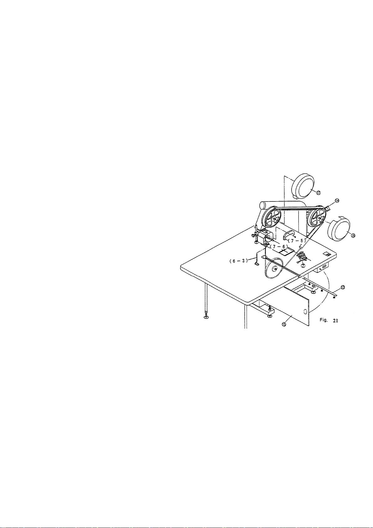
19. Removal of knife (see fig.21)
a) Remove the table plate (13).
b) Remove the safety fitting (6-3) of the knife guide.
c) Remove the grinder front cover (7-5) and the screws from the grinder (7).
d) Remove the top pulley cover (17) and the tension pulley cover (18).
e) Open the front cover (15).
f) Turn the tension handle to slacken the knife.
g) Remove the knife with extreme
care.
The knife installation
dimensions are given in para.3
on page 4.
(Caution)
Disconnect the power supply
cable plug from the outlet prior
to starting knife replacement.
It is recommended to put on
stainless steel mesh gloves
(safety gloves) for safety when
replacing the knife.
【G】OTHER
1. If there is lighting, stop the operation of the cutter and disconnect the power supply
cable from the outlet because the inverter may be damaged by lighting surge.
2. Disconnect the power supply cable from the outlet if the cutter is not being operated
for a long period of time.
3. Press the power supply off pushbutton switch on the switch box if the power supply
is interrupted during operation.
4. Maintenance
Open the pulley cover and the front cove and remove cut cloth waste etc. by a
vacuum cleaner etc. at regular intervals.
Each time the knife is ground. Remove grit from the grit tray by a vacuum cleaner
etc.
Fill the silicon oil tank located above the grinder with silicon oil at regular intervals.

-
10
-

-
11
-
機械
零件目錄
No.1
序號
Ref No
部件編號
Parts No
部件名稱規格
Description
數量
Customer
1 ZA3321 磨刀石Φ65*Φ59*Φ7.8*13 Grinding stone 2
2 700AB035 左砂輪軸芯 Axis for left wheel 1
3 700AB036 右砂輪軸芯 Axis for right wheel 1
4 JB2061 單列向心球軸承 608ZZ Bearing 2
5 700AB025 磨刀座固定杆 Fixed rod for the grinding base 2
6 ZW0065 梅花手 M6*35L Bearing 2
7 700AB038 右砂輪座 Base for right wheel 1
8 JH1032 圓錐形壓縮彈簧 Compressed spring 1
9 700AB037 左砂輪座 Base for left wheel 1
10 700AB021 砂輪滑座 Sliding base 1
11 700AB022 砂輪座 Base for wheel 1
12 700AB023 磨刀座擋片 Stopper for the grinding base 1
13 700AB024 磨刀座調節輪 Adjusted wheel for grinding base 1
14 700AB028 磨刀座調節杆 Adjusted rod for grinding base 1
15 700AB026 調整輪固定螺帽 Fixed nut for grinding stone 1
16 700AB027 磨刀座調節環 Adjusted ring for grinding base 1
17 ZW0334 刀具合蓋 175*85*15 Cover 1
18 700AB013 砂輪固定軸心 Fixed axis 1
19 700AB014 砂輪止滑圈 Ring 1
20 700AB043 刀具合固定座 Fixed base 1
21 700AA017 固定塊 Fixed block 1
22 ZW0053 梅花手柄(M8*40L) Shaft 1
23 700AB016 升降軸心 Axis (for OB-700/900) 1
1200AB001
升降軸心 Axis(for OB-1200)1
24 700AB011 刀座固定塊 Fixed block for the knife base 1
25 700AB017 刀座 Knife base 1
26 ZW0053 梅花手柄(M8*40L) Shaft 1
27 700AB018 墊塊 (刀座內) Wad (inside the knife base) 2
28 700AB051 刀帶擋杆 Stop rod for the band knife 1

-
12
-

-
13
-
機械
零件目錄
NO.2
序號
Ref No
部件編號
Parts No
部件名稱規格
Description
數量
Customer
1 JB2004 針狀軸承 NTB2035 Needle bearing 1
2 JH1081
壓縮彈簧ψ6.5*ψ35*105L*10 圈
Compressed spring 1
3 JB1025 軸承 UCF205 Bearing 1
4 JB1001 軸承 BLFL6J Bearing 1
5 700AB010 調整座擋板 Stopper for the adjusted base 1
6 700AB020 刀帶輪調整杆 Adjusted rod for the band knife 1
7 700AB062 手輪 3” Wheel 1
8 700AB050 刀帶輪軸心”短” Bearing for the band knife (short) 1
9 700AB046 刀片下底護罩 Cover for the knife 1
10 700AB041 刀帶輪 Band knife 1
11 JF3001
錐形止環ψ24*ψ21.3*ψ20*5
Stop ring 1組
12 700AB047 刀片下蓋護罩 Cover for the knife 1
13 700AB012 墊圈 Pad 1
14
ZW0336 刀蓋 555MM(鋁軌) Knife cover(FOR OB-700) 2
ZW0338 刀蓋 650MM Knife cover(FOR OB-900) 2
ZW0348 刀蓋 850MM Knife cover(FOR OB-1200) 2

-
14
-

-
15
-
機械
零件目錄
NO. 3
序號
Ref No
部件編號
Parts No
部件名稱規格
Description
數量
Customer
1 DM0201-2 鼓風機 220V Blast furnace 1
2 700AB034 傳動皮帶輪(小) Wheel for pass belt (small) 1
3 ZW0132 仿中古輪(美國輪)3” Wheel 4
4 700AB053 水平調整杆”長M18*220L Horizontal adjusted rod 4
5 DM0142
三相交流馬達(鋼板)4P 11HP 卧
Motor 1
6
700AA001 下層機組 Plate(for OB-700) 1
900AA001 下層機組 Plate(for OB-900) 1
1200AA001 下層機組 Plate(for OB-1200) 1

-
16
-

-
17
-
機械
零件目錄
NO.4
序號
Ref No
部件編號
Parts No
部件名稱規格
Description
數量
Customer
1 JB1025 培林 UCF205(需車溝) Bearing 1
2 700AB012 墊圈 Pad 1
3 JF3001
錐形止環ψ24*ψ21.3*ψ20*5
Stop ring 1組
4 700AB042 傳動皮帶輪(大) Wheel for pass belt (big) 1
5 JB1025 培林 UCF205 Bearing 1
6 JB2061 單列向心球軸承 608ZZ Bearing 1
7 JP0229 三角皮帶 B-37 Triangle belt 1
8 JB1027 培林 UCFC206 Bearing 1
9 JG6371 刮刀 37*20*0.5 Knife 1
10 JB1026 培林 UCF206 Bearing 1
11 700AB049 刀帶輪軸心”中
Axis for band knife wheel (medium)
1
12 700AB044 刀片上底護罩 Cover for knife 1
13 700AB041 刀帶輪 Wheel for band knife 1
14 JF3001
錐形止環ψ24*ψ21.3*ψ20*5
Stop ring 1
15 700AB012 墊圈 Pad 1
16 700AB045 刀片上蓋護罩 Cover for knife 1
17 700AB048 刀帶輪軸心”長”
Axis for band knife wheel (long)
1
18 700AB032 轉動刀帶輪 Turning wheel for band knife 1
19 JF3001
錐形止環ψ24*ψ21.3*ψ20*5
Stop ring 1
20 700AB012 墊圈 Pad 1

-
18
-

-
19
-
機械
零件目錄
NO.5
序號
Ref No
部件編號
Parts No
部件名稱規格
Description
數量
Customer
1 1200AA013 进風口 Wind outlet 1
2 700AA016 支撐杆 Holding rod 2
3 700AB054 水平調整杆”短”M18*195L Horizontal adjusted rod (short) 2
4
700AB029/030
刀具上導片/刀具下導片 Knife guide 1
5 ZA3253 工作臺 1500*1200*35MM Working table(for OB-700) 1
ZA3255 工作臺 1800*1500*35MM Working table(for OB-900) 1
ZA3256 工作臺 2400*1500*35MM Working table(for OB-1200) 1
6 DZ0301-1 變頻器 BBVFD007B21A Inverter 1
7 700AB031 刀具導片調節杆 Adjusted rod for the knife guide 1
8 700AA022 臺板固定片 Fixed plate for the table 4

-
20
-
This manual suits for next models
8
Table of contents


