osprey video RM12G-1 User manual

User Guide
RM12G-1

1
FEATURES
15.6” Display 4K 3840x2160 Resolution
2x 12G-SDI inputs plus 2x 3G/HD-SDI inputs (Level A/B)
Quad Link 12G Square Division.
Quad Link 12G Two-Sample Interleave (2SI)
1x HDMI2.0 up to 4K60
Quad View and PIP
3x HDMI1.4 up to 4K30
Tally
Content
1.Product Description ..................................................................2
2. Sund Shade Installation ...........................................................5
3. Menu Settings ..........................................................................6
4. Connecting the SDI signals .....................................................9
5. Signal Formats .......................................................................10
6. Accessories.............................................................................12
7. Specifications.........................................................................13
2
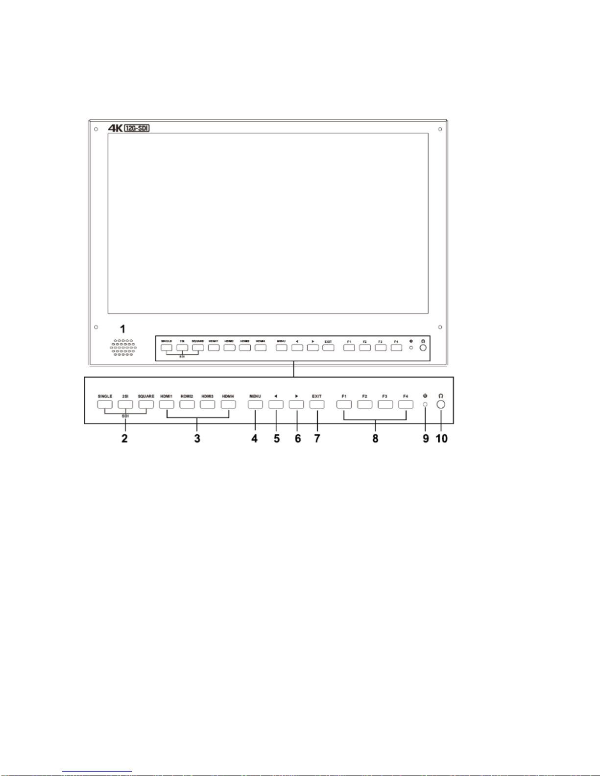
1. PRODUCT DESCRIPTION
1. Speaker
2. SDI
Press to monitor the signal input to each connector.
[SINGLE] Button
- Press the button to select SDI input for one channel.
- Mode changes in the order of [12G SDI 1] , [12G SDI 2] , [3G SDI 3] , [3G SDI 4].
[2SI] Button
-Press the button to select 2-SAMPLE Interleave SDI input signal through two or four SDI
input connectors.

3
- Mode changes in the order of [Dual-Link 2SI], [Quad-Link 2SI].
[SQUARE] Button
- Press the button to select Quad-Link Square Division mode.
3. HDMI 1 ~ 4
Press the button to select HDMI input.
4. MENU/ENTER
Press to enter menu.
Press to enter option in the menu.
5. ◄
Select option in the menu.
Decrease the option value.
Before enter the menu, single press to activate volume, press again to switch
between volume, brightness, contrast, color, hue, sharpness and backlight.
6. ►
Select option in the menu.
Increase the option value.
7. EXIT
Back or exit.
8. F1~F4 User defined buttons
Default function options:
F1:Display Mode F2:Display Rotate F3:Safety Marker F4:Aspect
(functions can be customized by long pressing any one of the 4 buttons)
9.Power Switch
10. Earphone jack
4
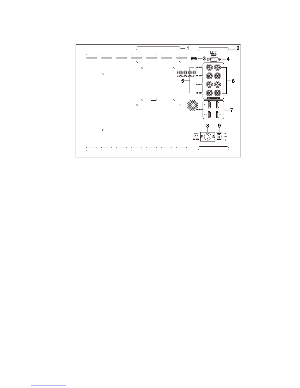
1. Handle
2. Connector protector
Preventing connectors from damage.
3. USB port (Only for firmware upgrades).
4. TALLY port
5. SDI (BNC)
Input connectors for SDI
6. SDI (BNC)
Loopout connectors for SDI.
Note –Loopouts are only active when the power is on.
5
7. HDMI input connectors
Input connectors for HDMI signals.
HDMI 1: HDMI2.0, supports 4K 60Hz
HDMI 2, HDMI 3&HDMI 4: HDMI1.4, supports 4K 30Hz
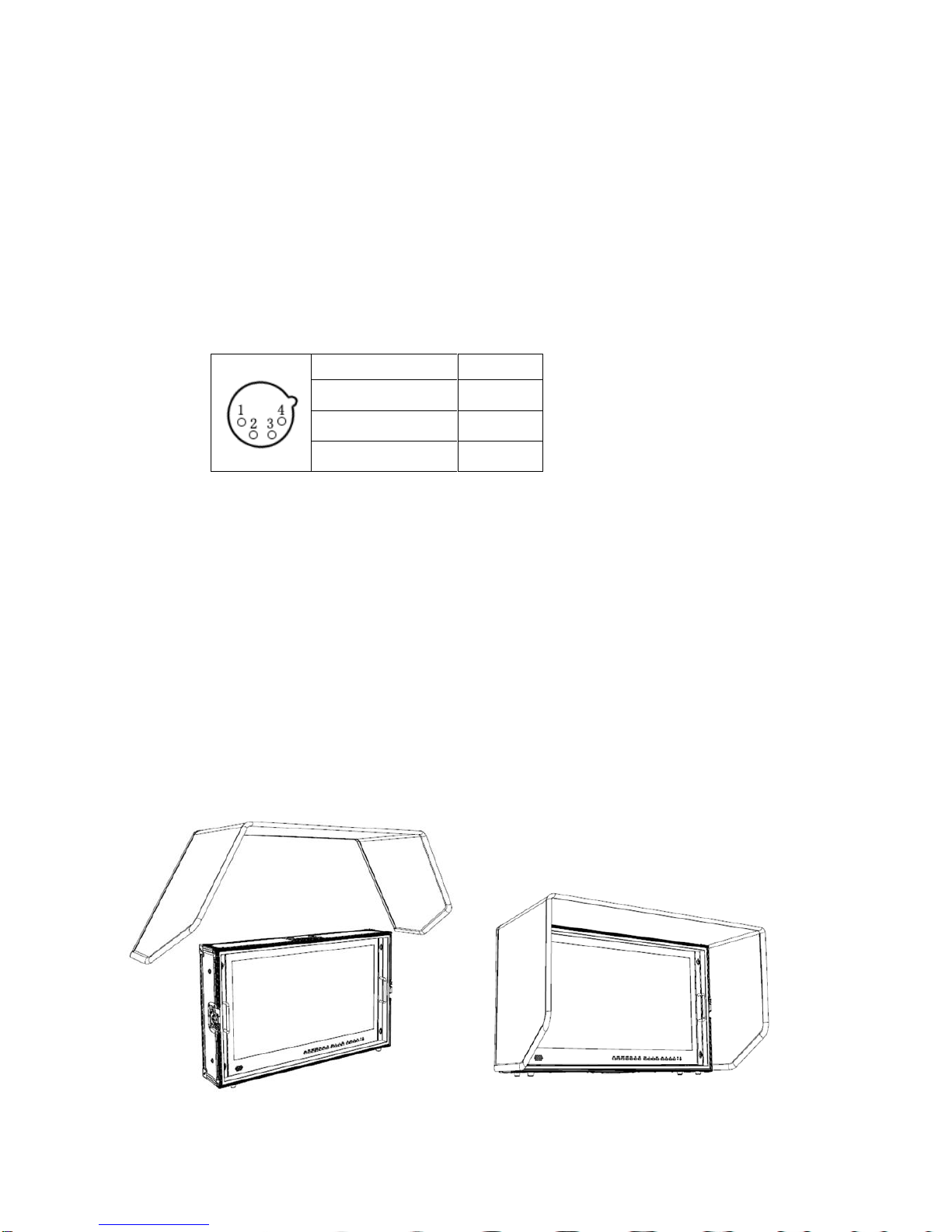
8. DC IN (XLR) terminal
Connects the DC power supply to the monitor.
Pin number
Signal
①
GND
②③
……...
④
+15V
9. Power switch
‖battery power; ○power off; | DC power
2. SUN SHADE INSTALLATION
Put the sun shade on the suitcase, and match the magnets on both sides.

6
3. MENU SETTINGS
3-1. F1~F4 user definable shortcut buttons
Long press any one of the 4 buttons for 3-5 seconds to activate shortcut
menu setting. Selected Setting will be highlighted in white, options will be
highlighted in yellow, unavailable options will be highlighted in gray.
Select option via “◄/►” buttons.
Then press “MENU” button to confirm to set as default option.
Functions can be customized to meet user’s needs: center marker, safety
marker, aspect marker, aspect, underscan, check field, freeze, pixel to pixel,
peaking, false color, display mode, disp rotate, disp mirror.
Default options:
F1:Display Mode F2:Display Rotate
F3:Safety Marker F4:Aspect
3-2. ◄/ ►Buttons Operation
Press ◄/►buttons to activate volume bar,
Within Menu use ◄/ ►buttons to select and change the desired options.
3-3. MENU Operation
When power on, press“MENU”on the device –Menu will display
Press ◄/ ►button to choose the menu item;
Then press“MENU”button to confirm;Press“EXIT”button to return / exit
7
menu.
Picture
Brightness
0~100
Contrast
0~100
Saturation
0~100
Hue
0~100
Sharpness
0~4
Temperature
9300,7500,6500,5800,User
Backlight
0~100
Function
Center Marker
ON, OFF
Safety Marker
OFF,95%,93%,90%,88%,85%,80%
Aspect Marker
Full,17:9, 16:9, 4:3,1.85:1,2.35:1
Aspect
Full,17:9, 16:9, 4:3,1.85:1,2.35:1
Underscan
ON, OFF
Pixel To Pixel
ON, OFF
Check Field
OFF, Red, Green, Blue
Freeze Input
ON, OFF
Peaking
ON, OFF
False Color
ON, OFF
Display Mode
1P,2P LR,2P TB,2P PIP,4P
Display
Setting
Display Rotate
0°,90°,180°,270°
Available only in single
display mode.
Display Mirror
OFF, L/R, U/D
Available only in dual
display mode

8
Select Region
Menu setting to region selected according to users’ needs.
Input
SDI 1, SDI 2 , SDI 3 , SDI 4, 2SI, SQUARE, HDMI 1, HDMI 2, HDMI 3,
HDMI 4
Audio
Volume
0~100
Audio CH
CH0&CH1, CH2&CH3, CH4&CH5, CH6&CH7,
CH8&CH9, CH10&CH11, CH12&CH13,
CH14&CH15
(HDMI mode unavailable)
System
Reset
Press to confirm after selected.
Menu Time
5~60s
OSD H Position
0~100 (To set menu display area)
OSD V Position
0~100 (To set menu display area)
Language
English, Chinese
Transparency
0~255 (To set menu transparency)
OSD Rotate
0°,90°,270°
Border Width
0~10
Border Color
R, G, B, W
Info
To display current information.

9
4. Connecting the SDI signals
The monitor accepts Single Link 12G/6G/3G/HD/SD-SDI, Dual-Link 3G-SDI,
and Quad-Link 3G/HD-SDI. Use the appropriate input connectors
depending on the input signal, referring to the tables on the next page.
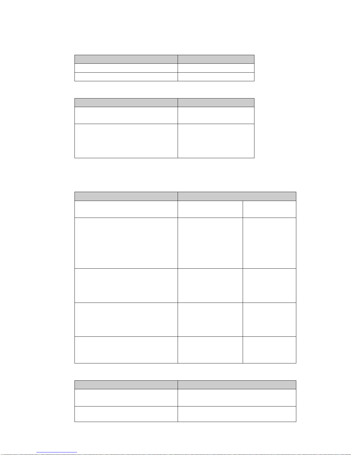
12G –SDI Single-Link Signal
3G-SDI Dual-Link signal
* 2-sample interleave signals *Square division signals
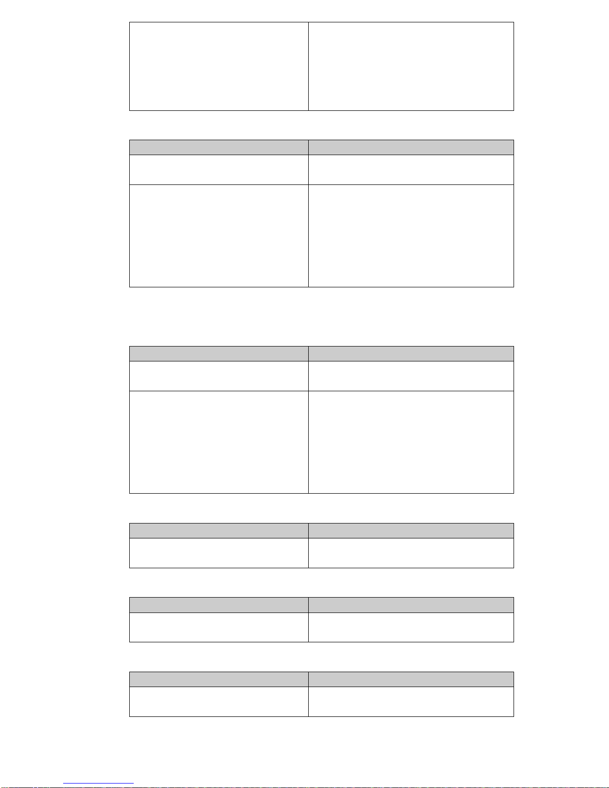
Quad-Link 3G/HD –SDI Signal
* 2-sample interleave signals *Square division signals
Image of square division signals
Connector
Input signal
SDI 1
12G SDI
SDI 2
12G SDI
Connector
Input signal
SDI 1
3G SDI Link 1
SDI 2
3G SDI Link 2
Connector
Input signal
SDI 1
Sub-image 1(upper left screen)
Sub-image 2( lower left screen)
SDI 2
Sub-image 3( upper right screen)
Sub-image 4(lower right screen)
Connector
Input signal
SDI 1
3G SDI Link1
SDI 2
3G SDI Link2
SDI 3
3G SDI Link3
SDI 4
3G SDI Link4
Connector
Input signal
SDI 1
Sub-image 1(upper left screen)
SDI 2
Sub-image 2(lower left screen)
SDI 3
Sub-image 3(upper right screen)
SDI 4
Sub-image 4(lower right screen)
Sub-image1
(upper left screen)
Sub-image 3
(upper right screen)
Sub-image 2
(lower left screen)
Sub-image 4
(lower right screen)
10
5. Available Signal Formats
SD-SDI
Signal system
Signal format
525i
4:2:2 YCbCr 10bits
625i
4:2:2 YCbCr 10bits
HD-SDI
Signal system
Signal format
1280×720
(23.98/24/25/29.97/30/50/59.94/60p)
4:2:2 YCbCr 10bits
1920×1080 / 2048×1080
(50/59.94/60i)
(23.98/29.97/24/25/30p)
(23.98/29.97/24/25/30Psf)
4:2:2 YCbCr 10bits
3G-SDI
Signal system
Signal format
1920×1080/2048×1080
(47.95/48/50/59.94/60p)
4:2:2 YCbCr 10bits
3G-LevelA /
DL 3G-Level B
1920×1080/2048×1080
(50/59.94/60i)
(23.98/24/25/29.97/30p)
(23.98/24/25/29.97/30Psf)
4:4:4 GBR 10bits
4:4:4 GBR+A 10bits
4:4:4 YCbCr 10bits
4:4:4 YCbCr+A 10bits
4:4:4 GBR 12bits
4:4:4 YCbCr 12bits
3G-LevelA /
DL 3G-Level B
1280×720
(23.98/24/25/29.97/30/50/59.94/60p)
4:4:4 GBR 10bits
4:4:4 GBR+A 10bits
4:4:4 YCbCr 10bits
4:4:4 YCbCr+A 10bits
3G-LevelA /
DL 3G-Level B
1920×1080/2048×1080
(50/59.94/60i)
(23.98/24/25/29.97/30p)
(23.98/24/25/29.97/30Psf)
4:2:2 YCbCr 10bits
DS 3G-Level B
1280×720
(23.98/24/25/29.97/30P
4:2:2 YCbCr 10bits
DS 3G-Level B
6G-SDI Single Link
Signal system
Signal format
3840×2160/4096×2160
(23.98/24/25/29.97/30p)
4:2:2 YCbCr 10bits
1920×1080/2048×1080
4:4:4 GBR 10bits
11
(47.95/48/50/59.94/60p)
4:4:4 GBR+A 10bits
4:4:4 YCbCr 10bits
4:4:4 YCbCr+A 10bits
4:4:4 GBR 12bits
4:4:4 YCbCr 12bits
4:2:2 YCbCr 12bits
6G-SDI Dual Link
Signal system
Signal format
3840×2160/4096×2160
(47.95/48/50/59.94/60p)
4:2:2 YCbCr 10bits
3840×2160/4096×2160
(23.98/24/25/29.97/30p)
4:4:4 GBR 10bits
4:4:4 GBR+A 10bits
4:4:4 YCbCr 10bits
4:4:4 YCbCr+A 10bits
4:4:4 GBR 12bits
4:4:4 YCbCr 12bits
4:2:2 YCbCr 12bits
12G-SDI Single Link
Signal system
Signal format
3840×2160/4096×2160
(47.95/48/50/59.94/60p)
4:2:2 YCbCr 10bits
3840×2160/4096×2160
(23.98/24/25/29.97/30p)
4:4:4 GBR 10bits
4:4:4 GBR+A 10bits
4:4:4 YCbCr 10bits
4:4:4 YCbCr+A 10bits
4:4:4 GBR 12bits
4:4:4 YCbCr 12bits
4:2:2 YCbCr 12bits
HD-SDI Quad Link
Signal system
Signal format
3840×2160/4096×2160
(23.98/24/25/29.97/30p)
4:2:2 YCbCr 10bits
3G-SDI Dual Link (2SI)
Signal system
Signal format
3840×2160/4096×2160
(23.98/24/25/29.97/30p)
4:2:2 YCbCr 10bits
3G-SDI Dual Link (Square Division)
Signal system
Signal format
3840×2160/4096×2160
(23.98/24/25/29.97/30p)
4:2:2 YCbCr 10bits

12
3G-SDI Quad Link (Square Division)
Signal system
Signal format
3840×2160/4096×2160
(47.95/48/50/59.94/60p)
4:2:2 YCbCr 10bits
3840×2160/4096×2160
(23.98/24/25/29.97/30p)
4:4:4 GBR 10bits
4:4:4 GBR+A 10bits
4:4:4 YCbCr 10bits
4:4:4 YCbCr+A 10bits
4:4:4 GBR 12bits
4:4:4 YCbCr 12bits
4:2:2 YCbCr 12bits
3G-SDI Quad Link (2SI)
Signal system
Signal format
3840×2160/4096×2160
(47.95/48/50/59.94/60p)
4:2:2 YCbCr 10bits
3840×2160/4096×2160
(23.98/24/25/29.97/30p)
4:4:4 GBR 10bits
4:4:4 GBR+A 10bits
4:4:4 YCbCr 10bits
4:4:4 YCbCr+A 10bits
4:4:4 GBR 12bits
4:4:4 YCbCr 12bits
4:2:2 YCbCr 12bits
6. Included ACCESSORIES
1. Folding sun shade cover 1 piece
2. Rugged Carry-on suitcase 1 piece
3. 15V DC adapter 1 piece
4. Battery plate bracket 1 piece
5. V-mount 1 piece
6. Base bracket 1 pair
7. TALLY connector (in bulk) 1 piece

13
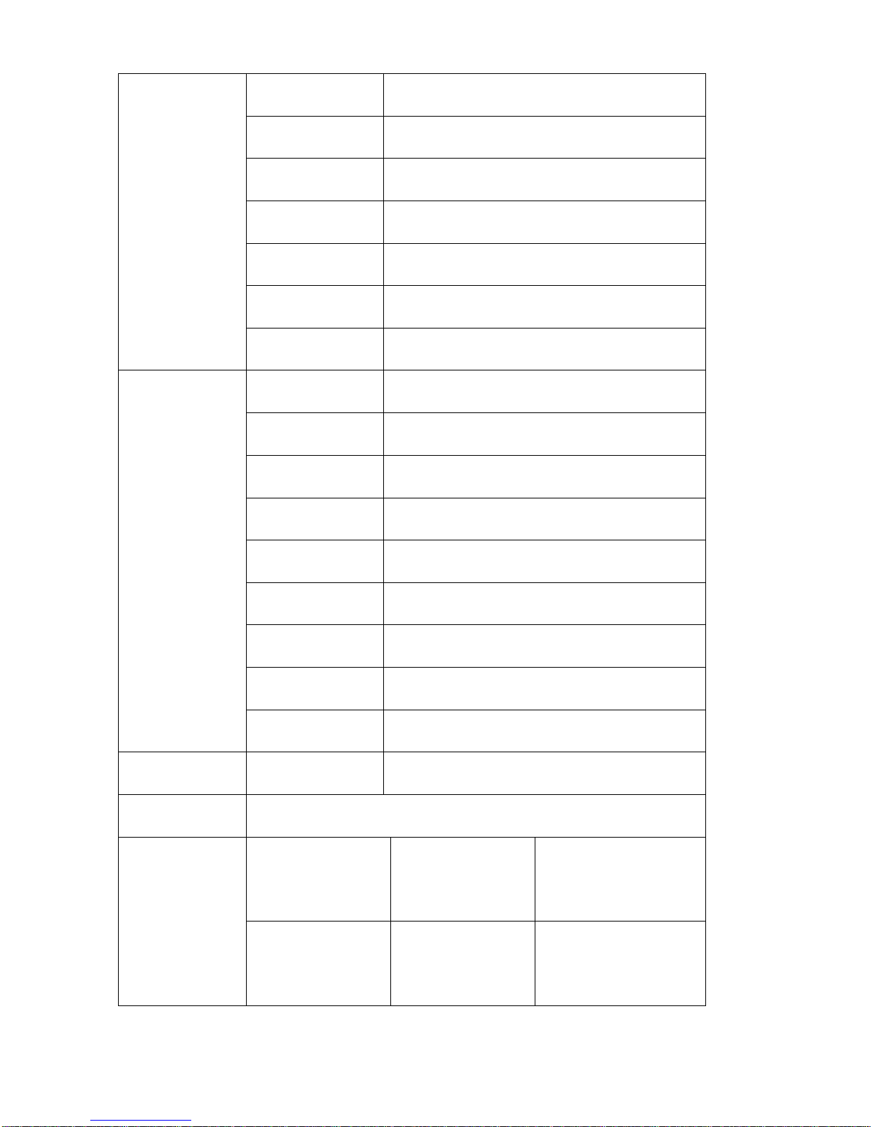
7. Specifications
Note: due to constant efforts to improve products and product
features, specifications may change without notice.
Display Screen
15.6”8bit IPS
Physical Resolution
3840×2160
Aspect Ratio
16:9
Brightness
330cd/㎡
Contrast
1000: 1
Viewing Angle
176°/ 176°(H/V)
Input Voltage
DC 12~24V(XLR)
Input Signal
3G-SDI, 12G-SDI, HDMI and TALLY
Output Signal
3G-SDI loop, 12G-SDI
Power Consumption
≤34W
Operating Temperature
0℃~60℃
Storage Temperature
-20℃~60℃
Dimension(LWD)
389×267×38mm
Weight
3.2kg/ 12 kg(with case)
Table of contents
Other osprey video PCI Card manuals


