OSS OSS-579 User manual

One Stop Systems
Table of Contents
1 Technical Information .......................................................................................................4
1.2 Product Information................................................................................................................... 4
1.3 General Specification ................................................................................................................. 5
1.4 Features ................................................................................................................................ 5
1.5 Block Diagram.......................................................................................................................... 6
1.6 Dimensions.............................................................................................................................. 6
1.7 Supported Use Cases .................................................................................................................. 7
1.7.1 x16 Use Case........................................................................................................................ 7
1.7.2 x8 Use Case ......................................................................................................................... 7
1.7.3 x16-x8,x8 Use Case ................................................................................................................ 8
1.8 Card Dipswitch Settings............................................................................................................... 9
1.8.1 x16 Host mode...................................................................................................................... 9
1.8.2 x8 Host mode ....................................................................................................................... 9
1.8.3 Target mode ........................................................................................................................ 9
1.9 LED Indicators.........................................................................................................................10
2 Hardware Requirements .................................................................................................. 11
3 Software Requirements ................................................................................................... 11
4 Unpacking.................................................................................................................... 12
5 Setup / Installation ......................................................................................................... 13
5.1 Installation Overview .......................................................................................................................13
5.2 Set Dipswitches .......................................................................................................................13
5.2.1 Set Target Card Dipswitches.....................................................................................................13
5.2.2 Set Host Card Dipswitches .......................................................................................................13
5.3 Prepare OSS Backpklane .............................................................................................................14
5.4 Install Target Card....................................................................................................................14
5.5 Install Host Card ......................................................................................................................15
6 Cable Installation ........................................................................................................... 16
7 Powering UP the unit ...................................................................................................... 17
8 Hardware Check ............................................................................................................ 17
8.1 Verify Board LEDs.....................................................................................................................17
8.2 Verify Adapter Card LEDs............................................................................................................18
9 Post Installation............................................................................................................. 19
9.1 Linux ...................................................................................................................................19
9.2 Windows ...............................................................................................................................22
10 How to Get More Help ..................................................................................................... 25
10.1 Contacting Technical Support.......................................................................................................25
10.2 Returning Merchandise...............................................................................................................25
10.3 Third Party Hardware & Software Support Policy ................................................................................25
OSS-579 Gen5 BP 2

One Stop Systems
1 Technical Information
1.2 Product Information
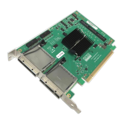
PCIe x16 Gen 5 host interface board with PCIe dual QSFP-DD cable connectors that can be configured as x16 or two x8 cable
ports.
•The cable adapter operates in host or target mode controlled with DIP switch settings.
•With the OSS-PCIe5-HIB732-x16-H installed in a PCIe slot in PCIe Gen 5 motherboard and the OSS-PCIe5-HIB732-x16-T
installed in an external target chassis full 128 GB/sec (full duplex) PCIe Gen 5 bandwidth is enabled using dual custom
QSFP-DD copper cables up to 2m in length.
•All PCIe devices in the remote chassis appear to the host CPU as directly connected PCIe peripherals on the PCIe switch
fabric.
OSS-579 Gen5 BP 4

One Stop Systems
1.3 General Specification
Form Factor PCIe 5.0 x16 add-in card
Dimensions 6.6” x 2.65” (16.76 x 6.73 cm) at 0.063” (1.6mm) thickness
Bandwidth 32GT/sec per lane, 128 GB/sec (full duplex) with x16 lanes
Connectors PCIe x16 card edge connector
Dual QSFP-DD connectors with custom pin-out (OSS cables required)
1 additional internal x8 PCIe ARF connector
Bracket Standard and low-profile brackets available
PCIe Switch Broadcom PEX 89072
•32 GT/sec 72 lane PCI Express Gen 5 Switch
•DMA Controller
•SSC Isolation
Switch Latency 150 nsec
Cable Types Supports the following cable types:
•Custom QSFP-DD PCIe CMI copper cables; .5m, 1m, 2m, 3m
•Remote power and reset control
Cable Connection Modes One x16 host connection via edge card to:
•One x16 cable connection
•Two x8 cable connections
Power 20 W Max
1.5A @3.3V
1.2A @12V
Operating Temperature 0 C to +40 C
Storage Temperature -40 C to 85 C
Operating Humidity 10% to 90% relative humidity non-condensing
Storage Humidity 5% to 95% relative humidity non-condensing
Agency Compliance Designed to meet the following agency standards:
•FCC—Part 15 Class A, 47CFR; Canada ICES-003, issue 4, Class A; Japan: VCCI, Class
A; CE Emission 2004-108EC
•UL/IEC 62368-1; Canada: CSA C22.2 No. 62368-1; Argentina: IEC62368-1; IEC 62368-
1 (CB Certificate and CB Test Report)
•CE Mark (EN55022 Class A, EN62368-1, EN55024, EN61000-3-2, EN610000-3-3)
•CISPR 22, CISPR 24, Class A; Australia/New Zealand AS/NZS CISPR 22, Class A
•RoHS 3 Compliance (Directive 2015/863/EC)
Drivers / Software Requires no software / driver installation
Supported Operating Systems Windows 10 & Windows 10 Pro
Windows 2012 Server and higher
Centos 7
Ubuntu 16x and higher
1.4 Features
•Operates at PCIe Gen 5 speeds up to 32 GT/sec per lane.
•Delivers 128 GB/sec (full duplex) bandwidth with x16 lanes.
•No drivers required.
•Utilizes custom QSFP-DD cables with sideband signals to support power control and remote reset (CMI functionality) x8
lanes per cable, 2 x8 cables used for x16 link.
•Can operate either Host or Target mode with the correct dipswitch settings.
OSS-579 Gen5 BP 5

One Stop Systems
1.5 Block Diagram
1.6 Dimensions
OSS-579 Gen5 BP 6

One Stop Systems
1.7 Supported Use Cases
1.7.1 x16 Use Case
Using two link cables connected between a host computer and a Gen5 backplane or an OSS expansion unit.
1.7.2 x8 Use Case
Using one link cable connected between a host computer and Gen5 backplane or an OSS expansion unit.
OSS-579 Gen5 BP 7

One Stop Systems
1.7.3 x16-x8,x8 Use Case
A single host computer connected to two OSS Gen5 backplanes or two expansion units via x8 link connection.
OSS-579 Gen5 BP 8

One Stop Systems
OSS-579 Gen5 BP 9
1.8 Card Dipswitch Settings
The following photos are three different dipswitch-mode settings on the OSS-579 adapter cards.
1.8.1 x16 Host mode
X16 Host mode requires two link cables
1.8.2 x8 Host mode
X8 Host mode uses only one link cable
1.8.3 Target mode
Target mode will only work on OSS backplane (Upstream slot #0).
1
HOS
T I
TARGET
= HOST= OFF
2
#PWR
ON
=
OFF
3
MAGMA
I
oss
=
OFF
4
PRTCFGO
=
ON
5
PRTC
FGl =
ON
6
PRTC
FG2
=
ON
7
DBG2
=
ON
8
DBG3
=
OFF
..{ " I
"'
l • I . • •,
,is111c·
"
...
t.~)
Ii
.,"
'°
1
,.
1,
J
Ii
.
""''
~
)
,
..
1,'
•
..
,
t I
•
..
,
,'
I
•
,n
.
I
r J •
..,
I
'I
ci
on
x16 Host
1
HOS
T I
TARG
ET = HOST =
OFF
2
#PWR
ON
=
OFF
3
MAGMA
I
055
= - -
OFF
--
4
PRTCFGO
=
OFF
5
PRTCFGl
=
ON
6
PRTCFG2
=
ON
7
DBG2
=
ON
8
DBG3
=
OFF
• . r
..
I
.,,
,.
1' • •,
«s111c·
"
,.
1.~)
Ii
·•""1
,.
1,
J
Iii
• t v
I.
'
r•
I•,
•
..
,
I I
~:• III , •
I
I
II
•
<1
•
II
..,
I
I "
II
.,
x8
Host
1
HO
ST
TARGET
= TARGET=
ON
2 #PWRON #PWRT
ON
=
OFF
3
MAGMA
oss
=
OFF
4
PRTCFGO
= ON
5 PRTCFGl =
OF
F Target
OSS
6 PRT
CFG2
= ON
7
DBG2
= ON
8
DBG
3 =
OFF

One Stop Systems
1.9 LED Indicators
579 LED Color NAME Normal
State Description
D1 Green Debug LED1 ON Reserved for Atlas switch heartbeat –
currently not implemented
D2 Green Debug LED2 ON currently unused
D3 Green Debug LED3 ON Power good 1.25V (switch serdes power)
D5 Green Aux Power ON 3.3V AUX power ON
D6 Green PGD - Power
Good ON All power good
D9 Green Link LED ON
Link Status:
-- Cbl link status (D8 -bottom cable)
indicates bottom cable link status only if in
x8x8 mode, rate as above.
-- Cbl link status (D9 –top cable) indicates
x16 link status of both cables or top cable in
x8x8 mode.
CR3 Red PEX Fatal Error OFF When ON= Error or Faulty
D7 Green PTGD - Port
Good ON
Card Edge Link status:
--ON (steady state) indicates Gen5 link
--Blink rate 2 Hz indicates Gen4 link
--Blink rate 1 Hz indicates Gen3 link
--Blink rate 0.5 Hz indicates Gen2 link
--Blink rate 0.25 Hz indicates Gen1 link
OSS-579 Gen5 BP 10

2
3
One Stop Systems
Hardware Requirements
This section provides the hardware parts needed for the OSS-579 adapter card to work. It is highly recommended to follow and
use the hardware requirements below.
1. Two OSS-57 card
a. OSS-579 Target card
b. OSS-579 Host card
2. Gen 5 PCIe x8 Cable (qty: 2): QSFP-DD Cables
3. Gen 5 x16 PCIe slot (computer motherboard)
4. Gen 5 OSS backplane (OSS-581)
a. Using a non-OSS backplane is not supported and will not work.
5. ATX Power Supply: Minimum of 400 Watt
To achieve superior performance and reliability it is recommended to use the Adapter cards with compatible OSS Gen5 backplane
(OSS-581), see photo below.
Software Requirements
The adapter card requires no driver installation in Windows OS and Linux.
Computer running the following operating systems:
a. Windows 10 or Windows 10 Pro
b. Server 12 and higher
c. Centos 7
d. Ubuntu 18 and higher
OSS-579 Gen5 BP 11

4
One Stop Systems
Unpacking
Check and identify the standard supplied item.
•Check the board make sure you have the correct Gen5 adapter card, see photo below.
•Inspect the board for physical defects and damages.
•If you ordered the adapter cards (host and target) with link cable(s), make sure the cables are included, see photo
below.
•The Gen5 cables (QSFP-DD) are sold separately.
OSS-579 Gen5 BP 12

One Stop Systems
5 Setup / Installation
The following steps will guide you through the installation of your OSS-579 card.
5.1 Installation Overview
Following steps provide the exact sequence that needs to be followed for setting up the OSS-579 adapter cards.
1. Set the Dipswitches
2. Prepare OSS backplane or expansion unit
3. Install the Adapter cards
4. Install QFSPD cables
5. Power UP the unit
6. Verify Installation
5.2 Set Dipswitches
Prior to installation, you must set the dipswitches on the OSS-579 adapter cards. Configure the card depending on what mode it
will be used (Host mode or Target mode).
5.2.1 Set Target Card Dipswitches
Set the dipswitches on the card to target mode, see photo below for correct settings
5.2.2 Set Host Card Dipswitches
Set the dipswitches on the card to host mode, see photo below.
OSS-579 Gen5 BP 13

One Stop Systems
5.3 Prepare OSS Backpklane
Prior to installation of the adapter card make sure the OSS backplane is properly configured. Use an OSS-581 Gen5 Backplane or
an expansion chassis equipped with Gen5 backplane, see photos below.
To setup and configure the Gen5 backplane, refer to the Gen5 backplane’s installation guide.
5.4 Install Target Card
Use the designated Target Slot / Upstream Slot on the backplane when installing the card.
•Plugin the target card in the upstream slot on the backplane.
•See photo below for the correct default location of the Target slot (Upstream Slot).
OSS-579 Gen5 BP 14

One Stop Systems
Align the card-edge connector on top of the PCIe slot # 0 (Target slot / Upstream slot).
•Slowly and gently push the card down until it is firmly seated
•Secure the card.
Photo below showing the Target card installation in the expansion chassis.
5.5 Install Host Card
Plug in the host card in the computer / server.
•The host card can only be installed in the computer. Install the Host card in an x16 Gen5 PCIe slot.
OSS-579 Gen5 BP 15

6
One Stop Systems
Cable Installation
Plugin the two cables to the target card. See photos below for the correct orientation of the cables when connecting to the card.
Photos below show the two link cables connected to the target card in the expansion chassis
Connect the other end of the cables to the host adapter card.
Use the diagram below as reference when connecting the cables between the host and targets cards.
OSS-579 Gen5 BP 16

7
One Stop Systems
Powering UP the unit
•Power ON the Gen5 backplane first.
•Turn ON the host computer
8 Hardware Check
8.1 Verify Board LEDs
After powering UP the host computer, the Target SLOT LED on the backplane will illuminate as solid green as shown below.
Check the board LEDS. A fully operational back plane will illuminate the following LEDs.
•D4 &D5
•D19: AUX power, solid green.
OSS-579 Gen5 BP 17

One Stop Systems
8.2 Verify Adapter Card LEDs
After powering ON the host computer, it will instantly power UP the target device.
•A fully operational adapter cards will illuminate the following LEDs (on both Host and Target cards).
OSS-579 Gen5 BP 18

One Stop Systems
9 Post Installation
Verify the OSS hardware after installation.
9.1 Linux
To check or verify if the OSS devices are detected, type or enter the command “lspci -vvv |grep c030”, see output below.
•It will show 46 total number of c030 device IDs, combining both OSS_579 adapter cards and the OSS_581 board.
•The c030 is the vendor device ID of the OSS_579 card and OSS_581.
The screenshot below shows 46 c030, indicating that the host device is communicating with the target and expansion backplane.
OSS-579 Gen5 BP 19

One Stop Systems
The screenshot below shows the output of “lspci -vvv |grep c030”with the OSS_579 host card only being detected.
•This is the single OSS_579 host card displaying 13 of c030 device IDs.
To check on the OSS-581 device hierarchy type or enter the command on a terminal window “lspci -vvtt”.
The screenshot below shows the hierarchy (tree-like structure) of the OSS_581 backplane without PCIe cards in the slots.
Below photo is the tree-like structure of the OSS_581 backplane with all 8 slots populated with different PCIe cards.
•Using the same command “lspci -vvtt”.
OSS-579 Gen5 BP 20
Table of contents
Other OSS Adapter manuals


