Ossa TR280i Instruction manual


2
1. Motorcycle specications
2. Engine part
2.1 Assembling or dismantling the engine from the chassis
2.2 Assembly and disassembly of engine parts
2.2.1 Engine start
2.2.2 Clutch
2.2.3 Gears
2.2.4 Ignition
2.2.5 Cylinder head
2.2.6 Cylinder
2.2.7 Piston and rings
2.2.8 Ignition
2.2.9 Ignition inner cover
2.2.10 Crankshaft
2.2.11 Water pump
3. Cycle part
3.1 Periodic maintenance chart and torque values.
4. Electrical part
4.1 Electrical diagrams
4.2 Injection
4.2.1 Kscan
4.2.2 Kwrite
5. Manintenance
5.1 Cylinder cover
5.2 Cylinder
5.3 Piston and rings
5.4 Crank
5.5 Crankshaft
5.6 Clutch
5.7 Gears
5.8 Transmission
5.9 Bearings
5.10 Seals
5.11 Sparkplug
5.12 Motor oil
CONTENTS

3
MOTOR
Cubic capacity 272,2 cc
Type Single cylinder, two-stroke, inverted engine with reed block
air intake.
Cooling system Liquid
Bore x stroke 76x60 mm
Fuel injection EFI Kokusan Batery-less System
Ignition Volante magnético digital CDI Kokusan
Clutch Hydraulic
TRANSMISSION
Gearbox 6 speeds
Transmission transmission by gears, nal transmission by chain
Lubrication mixture 100% synthetic oil lubrication 0.9%
Transmission and clutch oil 350 cc. of Gear Extreme type 75 W oil.
CHASIS
Type Cr-Mo / Forged aluminium with patented Fuel Tank by OSSA
Front suspension Marzocchi Hydraulic Fork with 40 mm al. stanctions.
Adjustable rebound and compression.
Shock absorber Progressive hydraulic monoshock TTX OHlins with
adjustable rebound and compression
Front brake ø 185 mm disc and 4 piston caliper
Rear brake ø 150 mm disc with 2 piston caliper
Front Wheel 28 spoke rims and 2,75x21 tires
Rear wheel 28 spoke rims and 4,00x18 tubeless tire
Engine protector Made of AA7075 T6
Kickstart pedal Forged aluminium
Gearshift and brake pedals Forged aluminium with retactable tips.
WEIGHT AND DIMENSIONS
Wheelbase 1.328 mm
Seat heigth 655 mm
Ground clearance (unloaded) 340 mm
Fuel tank capacity 2,6 litros
Weight (no fuel) 64 Kg
OSSA Factory S.L. reserves the right to modify this manual without notice. Kokusan, Marzocchi, OHlins
are registered brands and the use of their name is under license.
TECHNICAL FEATURES

4
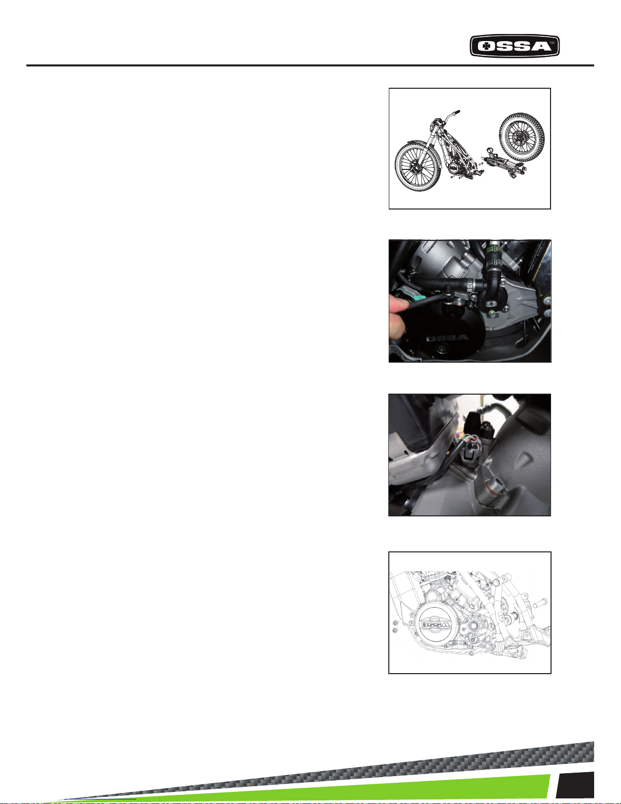
All operations on the engine of TR280i can be done without taking it appart from the chassis, except
when it is needed to work on the fuel pumps situated at the bottom of the fuel tank. For this case or to
work more comfortably on other operations, this is the procedure to disassemble the engine from the
chassis.
1. Take off the plastic lter cover and
seat base.
2. Take off the exhaust.
3. Take off the reed block and the throttle
body assembly.
4. Empty the cooling circuit and take off
the radiator.
ENGINE PART
5
ASSEMBLY AND DISASSEMBLY OF THE ENGINE FROM THE CHASSIS
9. Remove the bolts that hold the engine to the chassis,
to proceed with its disassembly.
8. Disconnect the cables from the injector.
7. Empty the clutch oil and remove the hose from the engi-
ne.
5. Take off the rear wheel, the swing arm, the shock absor-
ber and the brake pump from the chassis.

6
ENGINE PARTS
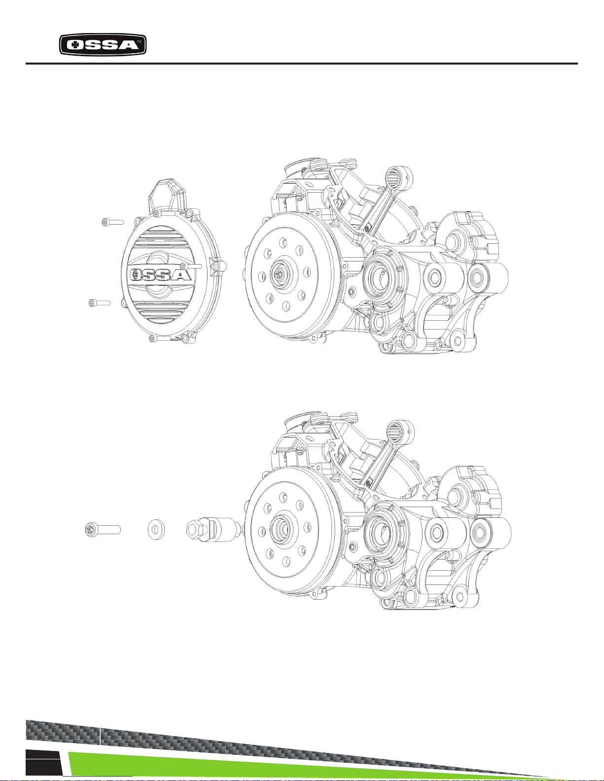
1- STARTING SYSTEM
Before taking appart the starting system, you must make sure the engine has no oil in the crankcase
leaning the bike to both sides. Also the clutch oil, removing the hose from the clutch cover.
Unscrew the 6 bolts that hold the clutch cover on the crankcase and take of the cover toghether with
the ignition system, kickstart pedal, shaft and gear.
Be careful to avoid damaging the gasket when removing the cover.

7
ENGINE ASSEMBLY AND DISASSEMBLY
2- CLUTCH
Once the clutch cover is out, you can see the clutch system. Follow these steps to take it appart.
Take out the 18 bolts which hold the clutch spring support plate.
Take off the spring, the pressure plate and the 18 clutch release arms to access the clutch discs.
Remove the clutch discs.

8
ENGINE PARTS
3- GEAR SHIFTING ASSEMBLY
Once you have taken out the clutch discs, the clip that holds the countershaft sprocket, the sprocket,
the bushing with its two O-rings and the gear shifting pedal, we can separate the gear assembly from the
engine.
The gear system comes out toghether with the shift shaft, and the gear selector assembly. To take it out of
the crankcase, it is necessary to remove the 5 centering screwst; and with some gear engaged, proceed
to take it out, as shown.
Take off the elastic ring ‘circlip’, the sprocket and the
gear shifting pedal.
Remove the 5 bolts that x the gear assembly to the crankcase. To
be able to take out the 3 bolts situated behind the clutch crown, the
crown must be turned until the rounded spaces for the key coincide
with the bolt heads.
After removing them, the gear assembly can be taken out of the crankcase.

9
ENGINE ASSEMBLY AND DISASSEMBLY
4- CYLINDER HEAD
It is recommendable to take out the cooling system hoses which are connected to the cylin-
der head with zip-ties, and the temperature sensor. After this, the cylinder head can
be disassembled by unscrewing the 8 bolts which hold it toghether with the cylinder.

10
ENGINE PARTS
5- CYLINDER
Before taking the cylinder appart from the engine, it is recommendable to remove the hoses from the
cooling system. To proceed, the 4 bolts that x the cylinder to the crankcase must be taken out.

11
ENGINE ASSEMBLY AND DISASSEMBLY
6- PISTON AND RINGS
Once the cylinder is out, the next step is to take out the cylinder and the rings, removing the locking
snap rings and the piston pin, we can take the piston appart from the rod, and then remove the rings
if desired.
12
ENGINE PARTS
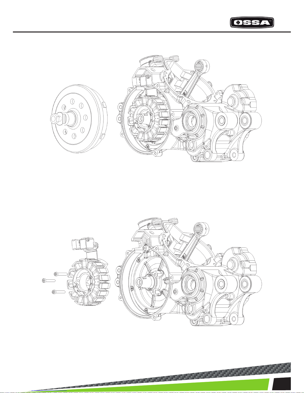
7- IGNITION SIDE
If we remove the ignition cover we can access the rotor. Once the rotor is out we can get to the stator.
Remove the 5 bolts from the ignition cover.
Using the special tool (included in the tool kit Ossa ref. 1499960211) we can take out the rotor.
13
ENGINE ASSEMBLY AND DISASSEMBLY
We can proceed to remove the stator, taking out the bolts that hold it toghether with the inner cranks-
haft cover, toghether with the pick-up.

14
ENGINE PARTS
8- INNER CRANKSHAFT COVER
Once the stator and rotor are out, the inner crankshaft cover can be removed. It is held toghether with
the crankshaft by 6 bolts. It is necessary to use the extractor kit which is part of the Ossa workshop
toolkit (ref. 1499960211). After this step, the crankshaft can be accessed.
After unscrewing the 6 bolts we attatch the extractor tool at the centre of the inner crankshaft cover
and we pull it out using the extractor that ts in the crankcase, while we screw the bolt in the middle.

15
ENGINE ASSEMBLY AND DISASSEMBLY
Using the tool we take out the inner crankshaft cover. Be careful to avoid damaging the gasket.

16
ENGINE PARTS
9- CRANKSHAFT
To remove the crankshaft it is necessary to use the special tools. (ref. 1499960211)
Follow these steps:
1
2
Unscrew the long pin that locks the bearing of the
crankshaft (1).
Heat up the area in the circle (2) with a heat
blower so that the crankshaft expands and makes
the extraction of the crankshaft easier.
17
ENGINE ASSEMBLY AND DISASSEMBLY
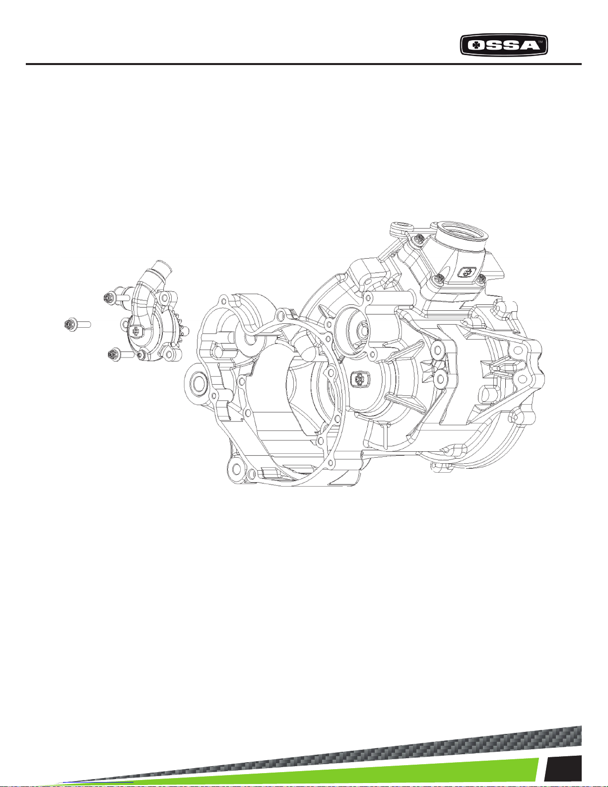
10- WATER PUMP
To remove the water pump, it is recommended to remove rst the rubber water hoses which are attat-
ched to it with metal zipties.
Take out the 3 bolts that hold the pump onto the crankcase.
The water pump can be removed.
18
ENGINE PARTS
RECOMMENDED TORQUE VALUES FOR THE ENGINE BOLTS
PART TORQUE (N·m)
Spark plug 11
Ignition xing points 7-8
Clutch xing points 7-8
Cylinder bolts 25
Reed block 7-8
The 18 bolts for the clutch spring support plate 3-4
Water pump 7-8
Clutch cover 7-8
Rotor 40
Water tubing ngs 10
Ignion cover 7-8
Oil draining cap 12
Bolts for the kickstart pedal 12-13
Bolts for the gear shiing pedal 7-8
Cylinder head 8-9
Cylinder nut 25

19
ENGINE ASSEMBLY AND DISASSEMBLY
1499960211 OSSA WORKSHOP KIT
PRIMARY BEARING TOOL CRANKSHAFT TOOL
CLUTCH POSITION TOOL IGNITION & STATOR TOOL
1000960211
MOTOR SUPPORT TOOL
RECOMMENDED TOOLS FOR SERVICING THE OSSA TR280i ENGINE
PART TORQUE (N·m)
Spark plug 11
Ignition xing points 7-8
Clutch xing points 7-8
Cylinder bolts 25
Reed block 7-8
The 18 bolts for the clutch spring support plate 3-4
Water pump 7-8
Clutch cover 7-8
Rotor 40
Water tubing ngs 10
Ignion cover 7-8
Oil draining cap 12
Bolts for the kickstart pedal 12-13
Bolts for the gear shiing pedal 7-8
Cylinder head 8-9
Cylinder nut 25

20
CYCLE PARTS
RECOMMENDED PERIODIC MAINTEINANCE
PART CHECK ADJUST REPLACE WASH GREASE/
LUBE
Rear shock Every ride -- Every 2 years -- --
Front fork Every ride When re-
quired
Every 2 years -- --
Front fork oil -- -- 60 hours -- --
Brakes Every ride When re-
quired
If damaged -- --
Swingarm and linkage Every ride -- If damaged Every ride After washing
Secondary transmis-
sion
Every ride When re-
quired
If damaged Every ride After washing
Steering bearings Every ride -- If damaged -- After washing
Wheel bearings 30 hours -- If damaged -- After washing
Disc brake rotors Every ride When re-
quired
If damaged -- --
Tyres Every ride -- If damaged -- --
Rims Every ride -- If damaged Every ride --
Spokes Every ride 5 hours If damaged Every ride --
Chassis Every ride -- If damaged Every ride --
Fuel tank Every ride -- If damaged Every ride --
Bolts, nuts Every ride When re-
quired
If damaged Every ride --
Crankcase protector -- First ride If damaged Every ride --
Protecve sckers Every ride -- If damaged -- --
Other manuals for TR280i
2
Table of contents
Other Ossa Motorcycle manuals


 Road Star owner's manual")

