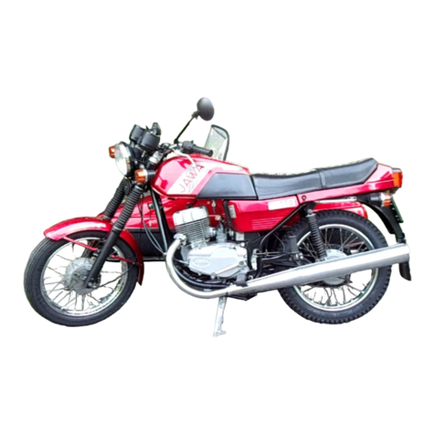
JAWA 250 TRAVEL User manual

1
OPERATING INSTRUCTIONS FOR THE MOTORCYCLE
JAWA
250 type 597-0
Travel
This document has been translated by the site
and is not an official Jawa document.

2
Dear Customer,
We appreciate very much the confidence you have shown by the fact that you chose a machine of our
brand.
Welcome to the world's big family of fans of JAWA motorcycles.
This guide is intended to provide basic information about the operation, maintenance and adjustment
of your motorcycle.
Please pay attention to its contents and read it carefully to the end.
We wish you much joy and pleasure with your JAWA motorcycle.

3
Warning:
We reserve the right to make changes, as a result of development, to images or descriptions
contained in this guide.
Dismantling and assembling the engine, not here described, require not only special tools but also
considerable repairing experience, and therefore we recommend entrusting the more complex repairs
solely to official workshops.
Identification number of motorcycle VIN (Vehicle Identification Number)
The motorcycle that you purchased is marked with an identification number on the VIN plate from the
manufacturer.
TLJ 597 0 XX 7 T 000 00x
T Europe XX Exemption
L Czech Republic 7 Code of production year (2007)
J Producer JAWA T Assembly Plant
597 Type 000 00x Frame serial number
0 Version

4
CONTENTS
I.DESCRIPTION AND RIDING INSTRUCTIONS ............................................................................. 5
1st TECHNICAL SPECIFICATIONS ................................................................................................. 5
2nd DESCRIPTION OF MOTORCYCLE .......................................................................................... 6
3rd DESCRIPTION OF ELECTRICAL EQUIPMENT ............................................... ........................ 7
4th RUNNING-IN MOTORCYCLE.................................................... ................................................ 8
5th INSTRUCTIONS ............................................... ......................................................................... 9
6th WHAT IS NECESSARY TO AVOID................................. ......................................................... 10
II. MAINTENANCE ................................................. ......................................................................... 11
PLAN OF MAINTENANCE WORK................................................................................................... 11
1st CLEANING MACHINE.. ...................................................... ...................................................... 12
2nd LUBRICATION........................................................................................................ .................. 13
3rd SERVICING BATTERY...................................... ....................................................................... 14
4th ADJUSTMENT ............................................. ................................................................... ......... 14
III. ASSEMBLY AND DISASSEMBLY WITHOUT SPECIAL TOOLS ……….................................... 16
Dismantling the front wheel ............................................ .................................................. ............. 16
Dismantling the rear suspension ......................................................... ........................................... 17
Removing the fuel tank ............................................... .................................................................... 17
Disassembly of the rear wheel ............................................... ....................................................... . 17
Tyre pressures ................................................ ........................................................................ ....... 17
TABLE OF FLUIDS AND LUBRICANTS .................................................. ...................................... 18
ELECTRICAL DIAGRAM ................................................................ ................................................ 19
Explanatory Text of Electrical Diagram ............................................... ............................................ 20
LIST OF ILLUSTRATIONS. ..................................................... .................................................. ..... 21

5
I. DESCRIPTION OF MOTORCYCLE AND INSTRUCTIONS FOR USE
1. TECHNICAL SPECIFICATIONS
Dimensions of motorcycle
Length 2070 mm
Width 770 mm
Height 1100 mm
Ground Clearance 110 mm
SeatHeight 820mm
Wheelbase 1350 mm
Weight and Load
Motorcycle Dry Weight 139 kg
Operating Weight 154 kg
Maximum Weight 334 kg
Payload 180 kg
Functional properties
Maximum Speed, rider seated normally 120 km / h
Fuel leaded or unleaded
petrol/gasoline, min. 91 octane
Fuel Consumption per 100 km 4.8 litres
Fuel Tank Capacity
17 litres, of which 2.8 litres
are reserve
Engine four-stroke engine, air cooled, petrol, electric
starter
Type TMEC type 253 FMM, 5 speed
Number of Cylinders 2
Format OHC
Bore 53mm
Stroke 53mm
Compression Ratio 9.2: 1
Power 13 kW / 7500
Lubrication pressure
Capacity 233.8 cubic centimeters
Clutch multiplate in oil bath
Transmission
Gearbox mechanical, 5 speed
Primary Reduction 3.631
1st gear 2.846
2nd gear 1.777
3rd gear 1.333
4th gear 1.083
5th gear 0.913
Oil Capacity 1.6 litres
Secondary Reduction 14/37 teeth
Chain 5/8" x 3/8" - 96 links
Carburettor twin, CV type, venturi diameter 26mm

6
Chassis
Front Suspension: telescopic fork with spiral springs, 2 x 200cc in volume
Rear Suspension: two separate units with hydraulic telescopic shock absorbers
Wheel Rims
Front Wheel 2.15 B - 18"
Rear Wheel 2.15 B - 18"
Tyres
Front 3.25 x 18 "
Rear 3.50 x 18 "
Tyre pressures
see Chapter on Chassis
Brakes
Front 320mm disc, hydraulically operated by a hand lever
Rear 160mm mechanical single leading-shoe, foot-operated lever with rod
2. DESCRIPTION OF MOTORCYCLE
The JAWA 250 Travel type 597 touring motorcycle designed for two persons is yet another reliable
motorcycle from JAWA, using a twin-cylinder four-stroke air cooled petrol engine with a very nice
simple design - see illustrated appendix.
This motorcycle, with less weight and a comfortable seat (in the Travel style), to which may be added
a back carrier for a top box, is intended for leisure use for younger and older sports-minded
customers.
Engine
The power unit is a twin-cylinder four-stroke engine with single overhead camshaft and a volume of
233.8 cubic centimeters, with a five-speed gearbox.
This engine has a maximum power of 13 kW at 7,500 RPM and a polished performance, and is a very
suitable power unit for this type of motorcycle.
The engine has an electric starter, which greatly simplifies operation.
Wheels
The front wheel is fitted with a disc brake and a plastic mudguard.
The rear wheel is equipped with a conventional drum brake operated rod.
The wheels are a classic spoked type.
Fuel Tank
Has a volume of 17 litres with 2.8 liters in reserve, is all metal, painted, equipped with a lockable cap.
Handlebars
Welded sports type with the possibility of adjustment, and with well-positioned levers and switches.

7
Ignition Switch
Performs the basic functions of electrical switching.
Instrument Panel
It is equipped with lights, electronic tachometer, and speedometer with metric trip meter.
Seat
It is shaped to suit the tank and side covers and provides comfortable seating for driver and
passenger.
Silencers
Exhausts are one-piece, in polished chrome form. Each has 2 catalytic converters, which serve to
reduce harmful emissions.
Footrests
The front footrests are attached via rubber dampening pads to the frame of the motorcycle, which
eliminate transmission of engine vibrations to the rider’s feet.
3. DESCRIPTION OF ELECTRICAL EQUIPMENT
This is a 12V installation. The source is an alternator, and it has a rechargeable battery. A wiring
diagram is shown in the Annex.
Alternator
The source of alternating current, with a rated voltage of 12V.
Battery
12V / 9Ah.
Starter
12V 580W, with a separate relay.
Ignition
Contactless electronic ignition with variable advance by means of a sensor that is part of the
alternator, together with a separate control unit.
Ignition Coil
The motorcycle is equipped with two ignition coils, which are mounted in the space beneath the tank.
Spark(ing) Plug
The motorcycle is fitted with NGK CR 7 HSA. Plugs from other manufacturers may be used if of
comparable values.
Ignition Switch (description of function)
Supplied by ZADI with three positions:
position 1) OFF - key in the left position (Fig. 1); all functions including ignition are off.
The motorcycle will not start, even with pushing. The key can be removed.
position 2) ON - The first position when turned to the right. Activated electrical system: ignition,
starter, direction indicators and instrument lights. Key cannot be removed.
position 3) LIGHTING – 2nd position when turned to right. This activates the system as in
position 2, but now switches on the headlight and rear light as well. Key cannot be
removed.
Brake Switch
See page 15, “Adjusting the brakes”, and the text that follows.

8
Direction indicators
12V / 10W lamps.
Front lamp
It is fitted with a halogen bulb H4 12V 60 / 55W, and parking light bulb 12V 4W.
Taillight
Fitted with 1-piece bulb 12V 5W.
Stoplight
Fitted with 12V 10W bulb.
Left switch (Fig. 9)
1. Headlight switch – high/low beam
2. Indicators, left/right
3. Headlight flasher
4. Warning horn
5. choke lever
Right switch (see Figure 7)
With two controls:
1. on/off headlight switch
2. starter switch
Instrument Panel
Instrument panel (see Figure 2) is equipped with (on the left) a tachometer, then warning light devices
and, on the right an electronic RPM meter.
On the control panel are the following lights:
1st upper left (green): LED function indicator lights
2nd bottom left (green): Neutral light
3rd top right (blue): Headlights
4th bottom right (red): vacant
Lighting equipment (speedometer and tachometer)
Baseless lamp is fitted with a 12V / 3W. Warning light panel uses baseless lamps 12V/2W.
4th RUNNING-IN MOTORCYCLE
A new motorcycle needs at least 1,500 – 2,000 km before its power can be fully utilized.
Conscientious running-in of machinery extends the life of the machine and also its maximum
performance. The motorcycle must be run in a flexible manner (don’t unnecessarily overload nor over-
rev the engine) and take care especially about these guidelines:
Do not over-rev the engine, especially in first gear at idle or when not on the move. Maximum speed
in these modes can not exceed 5,000-5,500 RPM in each gear.
The engine speed while driving should be raised to 6000 RPM and maintained about there, and
thus it is necessary to adapt one’s driving style (don’t slog or over-rev the engine).
The clutch may be used in jump-starting and while moving the motorcycle in reverse. Avoid slipping
the clutch to prevent damage to the plates.
Occasionally check and tighten all fasteners, especially the engine mounting and rear swinging arm.
Changing the oil in the engine will be necessary after the first 500 km (see chapter on oil changes).
Tighten all connections on the motorcycle and check that the battery contacts are clean.

9
after the first 500 km is necessary to replace the oil content of the front forks (see chapter on
changing the oil in the front forks).
5th OPERATING INSTRUCTIONS
Check before each trip
Visually inspect the brake fluid level (SYNTOL HD 205 of type DOT-3) and the hydraulic braking
system for leaks. Check function of brake switch. When the fluid level falls below half-way in the
control window, top up fluid. Inspection is performed while the handlebars are in the middle position.
(Fig. 3)
Check whether there is fuel in the tank and oil in the engine/gearbox. Inflow from the fuel tank to the
carburettor is controlled by a valve lever (Fig. 5):
1st, lever down ... ... ... ... ... ... ... ... ..fuel main supply on
2nd, lever horizontal ... .. ... ... ... ..... fuel off
3rd, lever up ... ... ... ... …. …... ... .... reserve
Check the engine oil: the level is measured after cleaning dipstick but without screwing it back into the
engine (see Fig.13).
Check function of electrical equipment, brake function, check engine for oil leaks, chain tension (see
Fig.16 & Fig.17 a), check the condition and pressure of tires.
Starting the engine
Insert the key and turn it to start position, open the fuel valve, open the carburettor choke lever (see
Figure 9) (see the description in chapter "Adjusting the carburettor“ and press the Start button on
the handlebar. Let the engine warm up for a time at low RPMs. After engine warm-up, turn the choke
off. After starting, check that all the electrical equipment works.
Ride
When starting off, pull in the left hand clutch lever, engage first gear with the left foot.
Move the lever to the bottom of the foot shift lever and the stop release (Fig. 4). Slowly release the
clutch lever while accelerating.
When you reach about 10-20 km / h, change up to the next gear.
Gearshift: 5.gear
4.gear
3.gear
2. gear
N - neutral
lever down - 1st gear
At the end of a trip, set the gear lever into neutral, the ignition key to “off“ position and shut off the fuel
supply (see Figure 1, Figure 4, Figure 5).
Securing Motorcycle
The motorcycle has two sets of keys (one spare), and this key:
- Locks the standard controls: handlebars can be locked while aligned to the right. Insert the
key into the lock, turn it to the right, push in the brass head lock, then turn they key to the left
and remove it. Handlebars are now locked. Unlocking is performed the opposite way.
- Locks and secures the seat (Fig. 20)
Insert the key into the lock, turn to the right and pull the lock outward.
Lift the seat in front for about 10-15 cm upward and move it forward to remove the seat from

10
the frame.
After removal of the seat it is possible to open the under-seat boxes.
Replacement is by reversing the order above.
6th WHAT IS NECESSARY TO AVOID
The engine is at a disadvantage when you let it run for any length of time at high speeds while
stationary, as it is not cooled as while driving. Cold starting without a short follow-up drive also harms
the engine.
Never rev a cold engine at high RPM, because cold oil will not sufficiently penetrate the hard-to-reach
components and you are in danger of seizing the engine. The run-in engine is capable of running at
high engine speeds (full throttle) after a short warming-up.
Don’t hold the clutch out for long. When riding uphill never help the engine by making the clutch slip,
but change down in good time to a lower gear. Do not ride for long distances in first gear.
Operating with naked flames or lighted cigarettes near the tank and the carburettor are not allowed
because of the risk of explosion.

11
2.. /)2.. 1)... 3)... 4)...
#! 1
$# /
!$!##! /
# /
%%" 0
# 0
!#! 1
" ! $" 1
"!( /)0
&!"
"&,!!" 0
! " /)0
!"$#!" 0
!#! 0
##!( /
!$#%!
%#")#&"#! /
#!" /)0
"("# /)0
"#" /
*
))$"#+!
$!#
'
/ """!(
0 %!(3)...
1 #4)...

12
SCHEDULE OF MAINTENANCE WORK:
At 500 km: Change oil in front fork and engine. Adjust the valve clearances, check
battery (clean contacts and check electrolyte level), tighten all fasteners,
check and adjust chain tension.
Every 2,500 km: check brake pads and shoes, lubricate lever pivots.
Every 5,000 km: change engine oil, adjust valve clearances, perform an overall fine-tuning
(including carburettor). Clean air filter (intake silencer). Check battery
(clean contacts and check electrolyte level). Check the setting of brakes and
adjust as necessary, tighten fasteners.
Remove brake pads, check lining thickness . If brake pads are less than 1
mm thick, the pads must be replaced. When reassembling the brake pads
ensure that they are aligned upwards in the caliper and that the projections fit
into the groove, making sure not to mix up the left and right pads. Change
front fork oil.
Every 10,000 km: Maintenance and care at this point includes everything that was included in
the maintenance at every 5,000 km. Replace front fork oil and check steering
head bearings.
Every 25,000 km or 2 years: Remove the brake calipers, inspect all the parts, replace brake fluid,
dust covers and piston seals. Have this done in an official workshop,
using the specified brake fluid for corrosion protection.
Every 50,000 km or 5 years: Dismantle the complete braking system (including master cylinder
and valve). Check all working parts, replace all rubber parts (seals,
dust covers and connecting hoses). Have this done in an official
workshop.
ATTENTION!
We recommend that any repairs to the hydraulic brakes should be conducted by an authorized
repair (JAWA brand service).
1st CLEANING MACHINE
Wash machine with water, preferably using a sponge. Take care that the water does not penetrate
into the carburettor, brakes or headlight. Dry and polish chrome-plated and painted parts with a cloth
or chamois leather. Painted parts may be brightened up occasionally with an appropriate polish.
Water on the outside of the cylinder will tend to discolour the cooling fins. It is best to start the engine
and let it run for a time, after which the heated water will evaporate. After cleaning, it is
recommended that the lever pivots be lubricated.

13
2 LUBRICATION
Changing engine oil
This is to be done after the first 500 km, and thereafter every 9,000 km.
Procedure: 1) warm up the engine to operating temperature
2) Unscrew the dipstick (filler)
3) Unscrew drain plug at the bottom of the engine number with a 17mm spanner
while cleaning coarse oil filter (see Figure 4)
4) after draining used oil, refit the drain plug and pour in 1.6 litres of motor oil
CAUTION:
This engine has a common oil filling for the engine and gearbox.
Cleaning of the coarse filter must be made at each oil change.
Recommended oil - Shell HELIX SUPER 15W-40 - or you may use oil from other manufacturers with
comparable values.
Change oil in front forks
Total oil capacity of the two shock absorbers is 400cc of oil, ie. 200cc in each leg. Apart from
damping, the oil serves for lubricating bushings and sliders.
Before the first oil change, we recommend that the front forks be cleaned out with two changes of
flushing oil.
a) First oil change after the first 500 km
b) Regular oil changes thereafter at every 5,000 km.
Procedure for an oil change in front forks
see section on Dismantling the front wheel.
Place an oil drain tray under the forks.
Remove the drain plug (see Figure 15, Figure 18).
Remove the upper filler screw.
After the old oil has drained, clean the forks out with flushing oil.
Check the soundness of the sealing washers of the drain plug and the upper threaded caps.
Fill both forks with fork oil.
Refit fork top upper threaded caps.
Lubrication and chain tensioning
see Adjustment

14
Air Filter
Clean the air filter cartridge washing in benzene and squeeze dry. Then apply a special spray-on air
filter oil, or an engine oil/petrol mix in the ratio 1:1 and squeeze out excess before refitting (Fig. 11).
3 SERVICING BATTERIES
The electrolyte level should be checked once a month. If it is below the mid-point between the upper
and lower level marks, top up with distilled water so that the level reaches the upper mark. Never refill
with acid! (Fig. 10)
The battery must be kept clean and dry, connecting cables must be protected against damage, and
the breather hose kept free from kinks.
In the event that the motorcycle had not been in use for a long period and the user notices that the
headlight is weak and the level of sound emitted by the horn is feeble the specific gravity of the
electrolyte may have decreased to the following levels:
YUASA batteries in areas with tropical or moderate climates to values lower than 1.20 kg/l
AWS battery in areas with a tropical climate to values lower than 1.18 kg/l; in areas with milder
climates to less than 1.21 kg/l.
for other types of batteries according to manufacturer's recommendations.
Recharging is appropriate if the motorcycle has not been used for more than a month. Remove
battery from the vehicle and check the volume of electrolyte. If necessary, fill the battery with distilled
water to the upper level. Optimum charging current is 0.9 A and the battery temperature during
charging should not exceed 55 degrees C.
The battery is fully charged when all the cells gas evenly and density values are no longer increasing.
Specific gravity of the electrolyte should reach values shown above after charging.
If necessary, top up the electrolyte after charging by adding distilled water. Generally, the charging
current (amps) ought to be no higher than one-tenth of battery capacity (Ah).
4th ADJUSTMENT
ADJUSTING MOTOR
TMEC type 250cc
Adjustment timing
You can check this but not adjust it, since it is a fixed setting. Checking is performed by stroboscope
while the engine is running (in approved workshop).
Adjusting the valve clearances is a high-precision operation, so it should be entrusted to a
professional JAWA service.
JAWA 250/597 Travel: intake valve: 0,07mm exhaust valve: 0,07mm
ATTENTION!
Proper valve adjustment will affect the performance and reliability of the engine. Therefore, we
recommend setting valves for the first time after 500 km and then after 6,000 km.
Adjusting the carburettor
These carburettors have two components that can be adjusted and they are the following:
1st: the idle screw on the right-hand side of the motorcycle (see Figure 8)
2nd: the choke (the engine cold start device) which is located on the left handlebar (Fig. 9).

15
Adjusting the clutch
For proper operation the clutch must be engaged with a set minimum clearance. To achieve the
minimum clearance use the 2 adjusters, one of which is located on the handlebars (Fig. 9) and the
other on the engine casing (Fig. 6, Figure 12).
Adjusting the brakes
Front brake (putting back into operation after maintenance or repairs)
Tighten all sealing joints, pour brake fluid into the brake master cylinder.
Repeatedly pressing the lever front brakes delivers brake fluid to the entire brake system
(to speed up the operation, carefully open and close the caliper brake fluid bleed screw while
operating the brake lever). To fill the entire system with fluid, the brake must be properly bled. Fit a
length of transparent tube to the bleed screw on the left side of the caliper brake slide and place the
other end of the tube into a glass of brake fluid. After operating the brake lever tighten the bleed
screw again. This operation must be performed until only clear fluid without bubbles is seen in the
transparent tube while brake lever is being operated. Ensure that the master cylinder is kept topped-
up during this operation. Adjust the stop-switch adjust so that it is just in contact with the brake lever
while not in use, but does not trigger the brake light.
ATTENTION!
Repairing front disc brakes: for safety reasons refer to a workshop.
Rear brake
1st: Adjust rear brake by turning the wing nut (Fig. 19).
2nd: Wing nut is to be tightened until brake shoes begin to operate. Then, about 1.5 turns is
released.
Proper adjustment of the rear brake is a prerequisite for proper operation of the brake switch.
Adjusting the front brake-lever screw to adjust the bias control of the main cylinder, free play of
between 0.3 and 0.5 mm. There should be no sponginess in the system. Adjust the brake light switch
so that the brake light comes on before the brake is applied.
Adjusting the rear brake light switch
1st Remove the locking pin of the double-ended Bowden cable, which is attached to the gear
lever and rear brake (see Figure 6, Figure 13).
2nd by resetting the appropriate endings of the double-ended find the location at which the switch
turns on the brake light as the brake lever is being operated, and still reliably returns to the OFF
position when pressure is removed.
3rd: Ensure proper fitting of cotter pins.
Chain Tensioning and lubrication
Place the motorcycle on its stand, loosen the rear wheel spindle nut and the nut on the rear sprocket
side. Then loosen the chain tensioners on both sides. Tension the chain gradually by tightening bolt
tensioners to the same value. The chain should be tensioned so that when lifted up at the lateral
reinforcement on the swinging arm its deflection should be 20 - 30 mm (Fig. 16, Figure 17).
ATTENTION!
It is necessary to maintain alignment (make sure front and rear wheels are in line to avoid biasing the
rear wheel to one side or the other). Alignment has an effect on driving the motorcycle.

16
Lubrication of the chain: the chain should be lubricated at least every 500-600 km, or whenever the
motorcycle is used in humid environments, or after a long break (after the rain, in the rain, and after
winter).
RECOMMENDATION
A properly and frequently lubricated chain will last longer than a neglected one. When properly
maintained and kept at the right tension, this chain should last from from 10,000 to 12,000 km.
ATTENTION!
In the case where the chain alone is changed it can happen that it will wear excessively. Always
replace the chain, drive sprocket and rear sprocket together.
BASIC headlamp alignment
Headlamp alignment is carried out under the following conditions:
a) the motorcycle is placed on a horizontal surface and load one rider on the bike without using the
stand
b) the tires are inflated to the prescribed pressure
Observe the height of the horizontal axis of the headlamp centre. Mark this height on a vertical wall 5
metres from the lamp. Note this position, and draw a horizontal line 6.5 cm on the wall below the level
of the mark.
Light up the dipped beam headlamp and set it so that the parameters of the beam correspond with
the sketch.
We recommend adjustment be made during a professional service.
III DISMANTLING AND REASSEMBLY WITHOUT SPECIAL TOOLS
ROLLING CHASSIS
Dismantle the front wheel
Unscrew the nut, loosen the wheel spindle and remove spring washer, loosen the pinch bolt
on the left and remove the wheel spindle. Be careful not to operate the front brake lever when the
wheel is removed as it would displace the brake pads. After removing the wheels, we recommend
you insert between the brake pads a retainer of the same thickness as the brake disc, or thicker, to
prevent inadvertent use of the brake.
When reassembling take care to remove the retainer (between brake disks), slip the brake disk
brakes carefully between the brake pads, clean and grease the wheel spindle. After inserting the
shaft into the wheel, replace and tighten the nut. Pump the front fork several times and only then
tighten the pinch bolt on the left of the slider.

17
ATTENTION!
When removing the front wheel is necessary to support either the front fork or back end of motorcycle,
so that the motorcycle does not roll forward and fall off the main stand.
Dismantling the rear suspension
Every 10,000 km mileage the rear suspension should be dismantled. Unscrew the units (dampers)
and check their function and tightness, which should be done on specialized equipment. Therefore it
is necessary to have repairs to the rear dampers carried out in a specialized repair shop. If the
damping unit cannot be repaired, it must be replaced with a new one. For repairs and replacement
you need to fit dampers as a pair. If you fail to do so, there may be misalignment because of
incompatible damping force of each damper.
Dismantling the fuel tank
Close the fuel valve and disconnect the hose. Once removed, detach the seat and the silentblock
rubber mountings holding the tank at the rear. Lift tank by the rear and move it backwards along the
longitudinal axis of the motorcycle, raising the tank off the leading silent blocks mounted on the
motorcycle frame.
Disassembly of the rear wheel
For dismantling the rear wheel, unscrew the wing nut from the brake rod, and the nut of the rear
spindle. Then remove the spindle, spacers, brake torque arm and rear brake rod and then carefully
remove the rear wheel. Reassembly is an easy reversal of the above procedure.
Tyre pressures (see diagram,)

18
TABLE LIQUIDS AND LUBRICANTS USE
Note A +lever pivots
brakes and clutches
+ Brake control
+ Pins stands
+ Bowden wire
B + engine lubrication
and gearbox
C + front telescopic
fork
D + twist grip gas
+ Swinging back fork
E + deposit back
sprocket
F + lubrication of wheel
bearings
G + secondary chain
H & brake fluid
Types of
Czech Republic
Trans Mogul 1990
Gyrol 90
Mogul Trans 80W/90
Gyrol 80W/90
Shell Super-HELIX
15W - 40
Mogul Super 15W-40
Grease LA2
Grease LA2
Grease LA2
Grease LA2
Spec Spray on chains
SYNTOL HD 205
viscous range
API GL 4
SAE 90
API GL 4
SAE 80W/90
API S6
SAE 15W - 40
API SC / CB or
API SF / CC
SAE 15W/40
ISO - L - XBCEB 2
ISO - L - XBCEB 2
ISO - L - XBCEB 2
ISO - L - XBCEB 2
Castrol Mo S2
DOT 3
Temperatures above
00 C
Year-round
Year-round
Gleitmo 592 and other

19
ELECTRICAL WIRING DIAGRAM

20
Legend for electric scheme
1. Indicators 11. Switch box
2. stop switch (front) 12. rear lamp
3. Right click 13. interrupter flasher
4. CDI - central control unit 14. starter relay
5. relay controller 15. battery
6. ignition coils 16. starter
7. stop switch (rear) 17. alternator
8. RPM counter 18. left switch
9. panel with instrument lights 19. horn
10.speedometer 20. headlamp
Colour coding cables
black R red
B white M blue
H brown /yellow
F violet
Table of contents
Other JAWA Motorcycle manuals

JAWA
JAWA RVM-600 User manual

JAWA
JAWA 350 Instruction manual

JAWA
JAWA F 350/634-5,8 User guide

JAWA
JAWA 1992 350/638 Instruction manual

JAWA
JAWA ZVL 210 User manual

JAWA
JAWA B User manual

JAWA
JAWA 559/04 User guide

JAWA
JAWA 638 Instruction manual

JAWA
JAWA 300 CL 2020 User manual

JAWA
JAWA Dandy MJ50 User manual