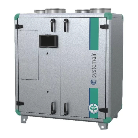
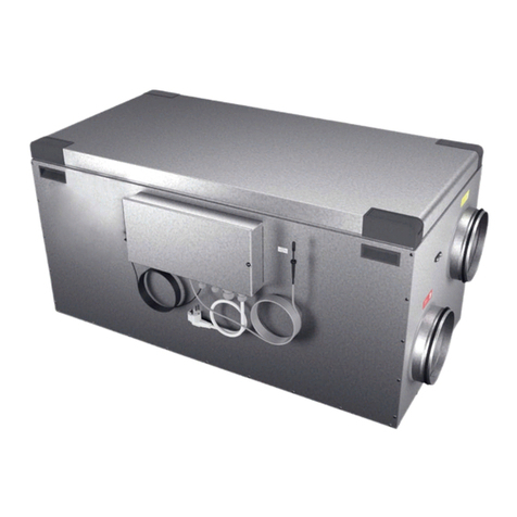
OSTBERG HERU SELECT Series User manual

HERU IQ – SELECT SERIES |EN
UPDATE
YOUR HERU
To ensure optimal function and
performance of your Heru Air Handling
Unit, please download and install
the latest software version
ostberg.com/updates
UPDATE
YOUR HERU
To ensure optimal function and
performance of your Heru Air Handling
Unit, please download and install
the latest software version
ostberg.com/updates
Other languages in digital format can be downloaded at www.ostberg.com


1270475_1 3
The manufacturer cannot be held liable for injury and damage to people or property that are caused
by incorrect installation, start up and/or incorrect use of the unit and/or failure to follow the pro-
cesses and instructions that are set out in the user manual ”Operation & maintenance”. For safety
reasons it is essential to follow the instructions in the user manual.
The warranty will be immediately invalidated in the event of injury that is caused by failure to follow
the instructions. Installation and commissioning must be performed by a professional in order for
the warranty to apply.
Short cuts:
• Log in Settings menu: Enter code 1991.
• Log in Service menu: Enter code 1199.
• Download the latest firmware version: Firmware.
• Download complete Modbus register: Modbus.
FIRMWARE MODBUS
• Download the app: HERU IQ App
APPLE GOOGLE

1270475_1
4
EN | TOC
Table of Content
1 INTRODUCTION.....................................................8
1.1 Product description. . . . . . . . . . . . . . . . . . . . . . . . . . . . . . . . . . . . . . . . . . . . . . . . . . . . . . . . . 8
2 SAFETY ...........................................................9
2.1 Warnings .................................................................9
2.2 General safety . . . . . . . . . . . . . . . . . . . . . . . . . . . . . . . . . . . . . . . . . . . . . . . . . . . . . . . . . . . . . 9
2.3 Product label (example) ....................................................11
2.4 Declaration of conformity. . . . . . . . . . . . . . . . . . . . . . . . . . . . . . . . . . . . . . . . . . . . . . . . . . . 12
3 WARRANTY. . . . . . . . . . . . . . . . . . . . . . . . . . . . . . . . . . . . . . . . . . . . . . . . . . . . . . . 13
3.1 Extent of the warranty. . . . . . . . . . . . . . . . . . . . . . . . . . . . . . . . . . . . . . . . . . . . . . . . . . . . . 13
3.2 General limitations in the warranty ..........................................13
3.3 Limitations in the warranty .................................................13
3.4 Service conditions during the warranty period .................................14
3.5 Corrective measures in the event of detected faults . . . . . . . . . . . . . . . . . . . . . . . . . . . . . 14
4 TRANSPORT AND STORAGE. . . . . . . . . . . . . . . . . . . . . . . . . . . . . . . . . . . . . . . . . . 15
4.1 General..................................................................16
4.2 Checking the delivery ......................................................16
5 INSTALLATION. . . . . . . . . . . . . . . . . . . . . . . . . . . . . . . . . . . . . . . . . . . . . . . . . . . . . 17
5.1 Assembly HERU Select frame – with or without legs. . . . . . . . . . . . . . . . . . . . . . . . . . . . . 17
5.1.1 Assemble the frame ........................................................ 17
5.2 Assembly and installation of the HERU Select Unit on the frame ..................19
5.2.1 Connect the modules ....................................................... 20
5.3 Lifting ..................................................................22
5.3.1 Separate units . . . . . . . . . . . . . . . . . . . . . . . . . . . . . . . . . . . . . . . . . . . . . . . . . . . . . . . . . . . . . 22
5.3.2 Mounted units on frame – lift with lifting yoke – straps – pipes .................... 22
5.4 Mounting principles .......................................................23
5.5 Mounting distance ........................................................23
5.6 Technical data ............................................................25
5.7 Mechanical connections ....................................................27
5.7.1 Connect the ducts to the unit ................................................ 27
5.7.2 Mount the duct sensor GT7 .................................................. 28
5.7.3 Mount the antenna for IQC .................................................. 28
5.8 Connecting the unit to the power source......................................29
5.9 Connections – main board and expansion board . . . . . . . . . . . . . . . . . . . . . . . . . . . . . . . . 30
5.10 Connections – Heating coil. . . . . . . . . . . . . . . . . . . . . . . . . . . . . . . . . . . . . . . . . . . . . . . . . 31
5.10.1 Heating coil – right ........................................................ 31
5.10.2 Heating coil – left ......................................................... 31
5.11 Connections – Electric battery ..............................................32
5.11.1 Electric battery – right. . . . . . . . . . . . . . . . . . . . . . . . . . . . . . . . . . . . . . . . . . . . . . . . . . . . . . 32
5.11.2 Electric battery – left ....................................................... 32
5.12 Connecting Modbus to external control equipment ............................33
5.12.1 RS485 ................................................................... 33
5.12.2 TCP/IP ................................................................... 33

1270475_1
TOC | EN
5
6 CONTROLLING THE UNIT ............................................34
6.1 Different ways to control the Select unit ......................................34
6.2 IQC Display ..............................................................34
6.2.1 Charge with USB-cable . . . . . . . . . . . . . . . . . . . . . . . . . . . . . . . . . . . . . . . . . . . . . . . . . . . . . . 34
6.2.2 Charge with the Active dock holder. ........................................... 34
6.3 Modbus .................................................................34
7 FINAL ROUTINES. . . . . . . . . . . . . . . . . . . . . . . . . . . . . . . . . . . . . . . . . . . . . . . . . . . 35
7.1 Preparations: . . . . . . . . . . . . . . . . . . . . . . . . . . . . . . . . . . . . . . . . . . . . . . . . . . . . . . . . . . . . . 35
8 COMMISSIONING ..................................................36
8.1 Adapting the unit for airflow in the opposite direction ..........................36
8.2 Starting the HERU unit . . . . . . . . . . . . . . . . . . . . . . . . . . . . . . . . . . . . . . . . . . . . . . . . . . . . . 36
8.3 Installation WIZARD .......................................................36
8.3.1 Setup Wizard menu overview ................................................ 36
8.3.2 Open the Setup Wizard ..................................................... 36
8.4 Configuring the unit for Modbus via RS485 . . . . . . . . . . . . . . . . . . . . . . . . . . . . . . . . . . . . 37
8.5 Configuring the unit for Modbus with TCP/IP ..................................37
8.6 Configuring the unit . . . . . . . . . . . . . . . . . . . . . . . . . . . . . . . . . . . . . . . . . . . . . . . . . . . . . . . 37
9 VARIMAX 25 NG . . . . . . . . . . . . . . . . . . . . . . . . . . . . . . . . . . . . . . . . . . . . . . . . . . . 38
10 OPERATION . . . . . . . . . . . . . . . . . . . . . . . . . . . . . . . . . . . . . . . . . . . . . . . . . . . . . . 40
10.1 Pairing units. . . . . . . . . . . . . . . . . . . . . . . . . . . . . . . . . . . . . . . . . . . . . . . . . . . . . . . . . . . . . 40
10.1.1 Main Display ............................................................. 41
10.1.2 Slave Display ............................................................. 41
10.2 The Display mode – Home screen simple and advanced . . . . . . . . . . . . . . . . . . . . . . . . . 42
10.2.1 Status bar icons of the Home screen – both simple and advanced screen ............ 42
10.2.2 Entering the basic settings for IQC Display ..................................... 43
10.2.3 Use the main menu . . . . . . . . . . . . . . . . . . . . . . . . . . . . . . . . . . . . . . . . . . . . . . . . . . . . . . . . 43
10.2.4 Select preset home screen .................................................. 43
10.3 Home screens ...........................................................44
10.3.1 Home screen simple ....................................................... 44
10.3.2 Home screen advanced . . . . . . . . . . . . . . . . . . . . . . . . . . . . . . . . . . . . . . . . . . . . . . . . . . . . . 44
10.4 Hotkey function .........................................................46
10.4.1 Temperature ............................................................. 46
10.4.2 Boost ................................................................... 46
10.4.3 External operation – is used to facilitate the lighting of a fireplace . . . . . . . . . . . . . . . . . 47
10.4.4 Activate Away mode ....................................................... 48
10.5 Activate screen lock ......................................................49
10.6 Scheduling ..............................................................49
10.6.1 Week scheduler ........................................................... 49
10.6.2 Holiday scheduler ......................................................... 50
10.7 Turn the unit off and on . . . . . . . . . . . . . . . . . . . . . . . . . . . . . . . . . . . . . . . . . . . . . . . . . . . 51
10.8 Use of the Alarm menu. . . . . . . . . . . . . . . . . . . . . . . . . . . . . . . . . . . . . . . . . . . . . . . . . . . . 51
10.9 Update firmware in the ventilation unit......................................52

1270475_1
6
EN | TOC
11 SERVICE AND MAINTENANCE .......................................53
11.1 Guide for – open doors – remove filter fans and rotor ..........................54
11.1.1 Open doors .............................................................. 54
11.1.2 Removing the filters – Select 1000 top connected ............................... 55
11.1.3 Removing the fans – Select 1000 top connected left ............................. 55
11.1.4 Removing the fans – Select 1000 side connected right. . . . . . . . . . . . . . . . . . . . . . . . . . . . 57
11.1.5 Removing the rotor package – Select 1000 . . . . . . . . . . . . . . . . . . . . . . . . . . . . . . . . . . . . . 58
11.2 Maintenance schedule ....................................................59
11.2.1 Maintenance every six months. .............................................. 59
11.2.2 Maintenance every year. . . . . . . . . . . . . . . . . . . . . . . . . . . . . . . . . . . . . . . . . . . . . . . . . . . . . 59
11.2.3 Regularly ................................................................ 59
11.3 Accessories and spare parts . . . . . . . . . . . . . . . . . . . . . . . . . . . . . . . . . . . . . . . . . . . . . . . . 59
12 CONTROL DIAGRAM. . . . . . . . . . . . . . . . . . . . . . . . . . . . . . . . . . . . . . . . . . . . . . . 60
13 CONNECTIONS – MAIN AND EXPANSION BOARD .......................62
13.1 Main Board .............................................................62
13.2 Expansion Board . . . . . . . . . . . . . . . . . . . . . . . . . . . . . . . . . . . . . . . . . . . . . . . . . . . . . . . . . 64
14 TROUBLESHOOTING. . . . . . . . . . . . . . . . . . . . . . . . . . . . . . . . . . . . . . . . . . . . . . . 66
14.1 Alarm ..................................................................66
14.2 Other malfunctions. . . . . . . . . . . . . . . . . . . . . . . . . . . . . . . . . . . . . . . . . . . . . . . . . . . . . . . 67
14.3 Troubleshooting chart . . . . . . . . . . . . . . . . . . . . . . . . . . . . . . . . . . . . . . . . . . . . . . . . . . . . 68

1270475_1
TOC | EN
7
APPENDIX 1 CONFIGURATION PROTOCOL................................70
APPENDIX 2 SETUP WIZARD . . . . . . . . . . . . . . . . . . . . . . . . . . . . . . . . . . . . . . . . . . . 73
2.1 Step 1 – RH/CO2/VOC Boost. . . . . . . . . . . . . . . . . . . . . . . . . . . . . . . . . . . . . . . . . . . . . . . . . 73
2.2 Step 2 – Heating and cooling . . . . . . . . . . . . . . . . . . . . . . . . . . . . . . . . . . . . . . . . . . . . . . . . 74
2.3 Step 3 – Temperature regulation . . . . . . . . . . . . . . . . . . . . . . . . . . . . . . . . . . . . . . . . . . . . . 77
2.4 Step 4 – Temp set point & Supply temp low . . . . . . . . . . . . . . . . . . . . . . . . . . . . . . . . . . . . 80
2.5 Step 5 – Switches .........................................................80
2.6 Step 6 – Alarm class .......................................................83
2.7 Step 7 – Alarm output & alarm relay..........................................84
2.8 Step 8 – Filter measurement. . . . . . . . . . . . . . . . . . . . . . . . . . . . . . . . . . . . . . . . . . . . . . . . . 85
2.9 Step 9 – Pressure input duct. . . . . . . . . . . . . . . . . . . . . . . . . . . . . . . . . . . . . . . . . . . . . . . . . 86
2.10 Step 10 – Dampers .......................................................88
2.11 Step 11 – Flow and regulation ..............................................88
2.11.1 Regulation type ”%” ...................................................... 89
2.11.2 Regulation type ”CPC” ..................................................... 90
2.11.3 Regulation type ”CAV”. . . . . . . . . . . . . . . . . . . . . . . . . . . . . . . . . . . . . . . . . . . . . . . . . . . . . 91
2.11.4 Regulation type ”VAV (SA Slave)” ............................................ 92
2.11.5 Regulation type ”VAV (EA Slave)” . . . . . . . . . . . . . . . . . . . . . . . . . . . . . . . . . . . . . . . . . . . . 93
2.12 Step 12 – Flow and regulation ..............................................94
2.12.1 Regulation type ”%” – Min speed . . . . . . . . . . . . . . . . . . . . . . . . . . . . . . . . . . . . . . . . . . . . 94
2.12.2 Regulation type ”CPC” – Min speed .......................................... 94
2.12.3 Regulation type ”CAV” – Min speed .......................................... 94
2.12.4 Regulation type ”VAV (SA Slave)” – Min speed ................................. 95
2.12.5 Regulation type ”VAV (EA Slave)” – Min speed ................................. 95
2.13 Step 13 – Flow and regulation ..............................................96
2.13.1 Regulation type ”%” – Max speed. . . . . . . . . . . . . . . . . . . . . . . . . . . . . . . . . . . . . . . . . . . . 96
2.13.2 Regulation type ”CPC” – Max speed .......................................... 96
2.13.3 Regulation type ”CAV” – Max speed . . . . . . . . . . . . . . . . . . . . . . . . . . . . . . . . . . . . . . . . . . 96
2.13.4 Regulation type ”VAV (SA Slave)” – Max speed ................................. 97
2.13.5 Regulation type ”VAV (EA Slave)” – Max speed ................................. 97
2.14 Save settings . . . . . . . . . . . . . . . . . . . . . . . . . . . . . . . . . . . . . . . . . . . . . . . . . . . . . . . . . . . . 98

1270475_1
8
1 Introduction
1.1 Product description
The energy recovery units HERU Select are designed for supply air and exhaust air ventilation with
cooling and heat recovery.
HERU Select is modular based, with one middle rotor module and two side modules standing on a
frame. The side modules can be either top- or side connected.
Features
• Inbuilt after-heater.
• ePM1 filters.
• Display for operation and monitoring of the unit and a active dock holder for charging.
• USB to RJ-45 cable for connecting the display to the unit and a standard USB-cable.
• Modbus communication via RS485 and TCP/IP.
• High temperature efficiency
• Energy saving
• Low sound levels
• Safe operation
• High reliability

1270475_1
Safety | EN
9
2 Safety
2.1 Warnings
2.2 General safety
WARNING! A warning states a risk of personal injury.
CAUTION! A caution states a risk of damage to equipment.
WARNING! Watch out for sharp edges and corners on the unit. Use protective gloves.
WARNING! In accordance with IEC 60335-2-40, this unit is not intended to be used by people (including
children) who have physical, sensory or psychological impairment, or lack of experience and knowledge,
unless they have received guidance and instruction on how to use the unit by a person who is responsible
for their safety. Children must be supervised to ensure that they do not play with the unit.
WARNING! Pay attention to the weight of the unit and its parts during mounting and maintenance.
WARNING! Rotating, hot and electrical components can cause serious injuries.
WARNING! Ducts must be connected and doors/cover must be closed and fastened before connecting
the unit to the electrical supply. Risk of personal injury from rotating parts, hot and electrical components.
WARNING! The electric after-heater may remain hot even after the power has been disconnected for
service and maintenance.
WARNING!
All changes or additions of electrical components must be performed by a qualified electrician.
WARNING! All electrical installations must be performed by a qualified electrician.
WARNING! Ensure that the power cable is not damaged during mounting and installation.
WARNING! The unit may not be started until the installation is completely finished and the ducts have
been connected.
WARNING! The safety switch must not be used for normal starting and stopping of the unit. Use the
accompanying display.

1270475_1
10
EN | Introduction
WARNING! The ”all pole disconnect safety switches” for all circuits must be switched off before the cover
of the electrical distribution box or the doors/cover of the unit are opened/removed from the unit.
WARNING! Deviations regarding EN 60335-1 section 30.2.1 occur. The ventilation unit contains limited
amounts of flame-resistant or inflammable materials in line with EN 1886. Fire and smoke dampers should be
in-stalled in the ventilation system at penetrations of fire barriers. Local fire safety regulation must be followed.
Air temperatures exceeding 85 C or excessive deposition of inflammable substances should be avoided.
WARNING! Before servicing the unit, power must be disconnected for two minutes for the fans to stop.
WARNING! The unit must always be equipped with a type A or B, 30 mA residual current device (RCD)
and a safety switch, which must be mounted close by.
WARNING! Condensation may appear in units containing cooling battery or in units installed in cold
climate. Installation must allow for proper drainage through water traps to avoid dangerous microbial
growth.
CAUTION!
We recommend always installing a spring-return damper in the ducts for fresh air and exhaust air.
CAUTION!
Do not walk, tread or stand on top of the unit.
CAUTION! Always turn off the unit with the wireless IQC Display before cutting the power.
CAUTION! Do not connect an exhaust air type tumble dryer or drying cabinet to the system due to the
high air humidity.
WARNING! All operations on the unit and its peripheral equipment must be performed in accordance
with local laws and regulations.
CAUTION! If the unit is installed when it is cold outside / in the winter and it will not immediately be put
into use, the ducts must be plugged again otherwise there is a risk of condensation and the unit freezing.
CAUTION! The unit must not be turned off for longer periods unless the duct connections for outdoor air
and extract air are re-plugged due to the risk of condensation and freezing.
CAUTION! In the event of any interruption in power, the settings will be saved. Date and Time are saved
for 24 hours. In longer interruptions, Date and Time must be reset.
WARNING! Breathing protection and protective clothing must be used due to the risk of breathing in and
spreading dust when handling used air filters.

1270475_1
Safety | EN
11
2.3 Product label (example)
1. Product name
2. Item number
3. Maximum power – fans
4. Maximum power – heater
5. RPM at maximum power
6. Serial number
7. Serial number as bar code
8. QR-code for product web page
8
7
6
5
4
3
2
1

1270475_1
12
EN | Safety
This document is digitally signed.
EU DECLARATION OF CONFORMITY
We hereby confirm that our products comply with the requirements in the following
EU-directives and harmonised standards and regulations.
Manufacturer: H. ÖSTBERG AB
Industrigatan 2
SE-774 35 Avesta, Sweden
Tel No +46 226 860 00
Fax No +46 226 860 05
http://www.ostberg.com
info@ostberg.com
VAT No SE556301220101
Products: Bidirectional ventilation unit RVU: HERU® 95 T EC, HERU® 100 T EC, HERU® 160 T EC,
HERU® 200 T EC, HERU® 300 T EC, HERU® 100 S EC, HERU® 160 S EC, HERU® 200 S EC
HERU® 300 S EC, HERU® 70 K EC, HERU® 50 LP EC, HERU® 90 LP EC, HERU® 180 S EC 2,
HERU® 250 T EC, HERU® 130 S EC, HERU® 250 S EC
Bidirectional ventilation unit NRVU: HERU® 400 T EC, HERU® 600 T EC, HERU® 800 T EC,
HERU®, 1200 T EC, HERU® 400 S EC, HERU® 600 S EC, HERU® 800 S EC,
HERU® 1200 S EC, HERU®Select
This EU declaration is applicable for products including our accessories for mounting and installation only if the
installation is made in accordance with the enclosed installation instructions and that the product has not been modified.
Radio Equipment Directive (RED) 2014/53/EU
Harmonised standards:
EN 300 220-2:2018 V3.1.1
EN 303 446-1:2019 (EN 55014-1:2017, A11, EN 55014-2:2015, EN IEC 61000-3-2:2019, EN 61000-3-3:2013, A1)
EN 301 489-3:2019
Machinery Directive (MD) 2006/42/EC
Harmonised standards:
EN ISO 12100:2010
EN ISO 13857:2019
EN 60204-1:2018
EN 60335-1:2012, AC 1, A 13 R1, A 11, A 12, A 13, A 1, A 14, A2, A15
EN 60335-2-40:2003, A13, A2, A12, A1, A11, C1, C2
EN 60335-2-30:2010, A11, A1, A12
Ecodesign Directive 2009/125/EC
Harmonised regulation:
1253/2014 Ecodesign requirements for ventilation units
1254/2014 Energy labeling of residential ventilation units
Standards:
RVU: SS-EN 13141-7:2021 or NRVU: SS-EN 13053:2019
RoHS Directive 2011/65/EU
Harmonised standards:
EN IEC 63000:2018
Avesta 2022-04-25
Mikael Östberg
Product Manager
2.4 Declaration of conformity.

1270475_1
Warranty | EN
13
3 Warranty
The warranty’s validity according to the purchase agreement is calculated from the day of purchase.
3.1 Extent of the warranty
The warranty covers faults that occur during the warranty period that have been notified to the
dealer or which have been verified by H.Östberg AB (underwriter) or the warranty provider’s repre-
sentative. Faults are defects in manufacture and materials as well secondary failures that occur due
to these.
The above faults must be remedied so that the product is operational.
3.2 General limitations in the warranty
The warranty provider’s liability is limited according to these warranty conditions and the warranty
does not cover injury or damage to people or property. Verbal promises that are made in addition to
the warranty agreement are not binding on the warranty provider.
3.3 Limitations in the warranty
The warranty applies on condition that the product is used in the normal manner or under equiva-
lent circumstances and that the user instructions are followed.
The warranty does not cover faults that are caused by:
• Transport of the product.
• Unintended use or overloading of the product.
• Failure on the part of the user to follow the instructions regarding installation, use, maintenance
and care.
• Incorrect installation or incorrect positioning of the product.
• Conditions that are not the responsibility of the warranty provider, e.g. excessive variations in
voltage, lightning strike, fire and other accidents.
• Repairs, maintenance and changes that are performed by unauthorised parties.
The warranty does not cover:
• Faults that do not affect operation, for example scratches to the surfaces.
• Parts that are exposed to greater risk of fault than normal due to handling or normal wear and
tear, for example lamps, glass, ceramics, paper or plastic parts, filters and fuses.
• Settings, information on use, care, service or cleaning that are typically described in the user
instructions, or damage that is caused by the user failing to observe warnings or installation
instructions, or inspection of such.
The warranty provider is only responsible for the operation if approved accessories are used. The
warranty does not cover product faults that are caused by other manufacturers’ accessories or
equipment.
The unit’s current settings must be recorded in the installation and assembly instructions at installa-
tion in order to avoid costs in the event of fault. The warranty provider is not responsible for costs
such as adjustment costs when changing fans and main boards in the unit.

1270475_1
14
EN | Warranty
3.4 Service conditions during the warranty period
The conditions apply according to the agreement with the local dealer.
3.5 Corrective measures in the event of detected faults
If a fault is detected, the customer must notify this to the dealer.
Shipping damage must be notified to the shipping agent upon delivery. State which product applies
(part and serial number as per the name plate) and describe the fault and how this has occurred as
accurately as possible.
In order for warranty repair to be performed, the customer must demonstrate that the warranty is
valid by presenting a purchase receipt. Once the warranty period has expired, claims that were not
made in writing before expiry of the warranty period will not be valid. In other regards, this shall
occur in accordance with the sales conditions.

1270475_1
Transport and storage | EN
15
4 Transport and storage
WARNING! Power must be cut to the unit for two minutes before work can be started.
WARNING! The safety switch must be switched off when the cover of the electrical distribution box or
the doors/cover of the unit are opened/removed from the unit.
WARNING! The unit may not be started until the installation is completely finished and the ducts have
been connected.
WARNING! Rotating, hot and electrical components can cause serious injuries.
WARNING! Ensure that the installation fulfils local and national fire safety requirements.
WARNING! Ensure that the ducts are coupled in the correct position on the HERU unit.
WARNING! The antenna must NOT be attached against any metal surface or object, as this will block the
signal
CAUTION! If the unit is installed when it is cold outside / in the winter and it will not immediately be put
into use, the ducts must be plugged again otherwise there is a risk of condensation and the unit freezing.
WARNING! Make sure that the electricity is switched off during the entire assembly process.
WARNING! All operations on the unit and its peripheral equipment must be performed in accordance
with local laws and regulations.
WARNING! All electrical installations must be performed by a qualified electrician.
CAUTION! Do not connect an exhaust air type tumble dryer or drying cabinet to the system due to the
high air humidity.
CAUTION! Installation and commissioning must be performed by a professional in order for the warranty
to apply.

1270475_1
16
EN | Transport and storage
4.1 General
The HERU unit must be stored in a protected and dry space before installation.
4.2 Checking the delivery
1. Inspect the unit carefully upon delivery to check for any damage that may have occurred during
transport. Immediately inform the manufacturer in the event of severe damage.
2. Note! The manufacturer cannot be held liable for damage to the unit during transport,
even if the manufacturer has appointed the shipping agent.
3. Check that the delivery contains all ordered parts.
The following parts will be included in the HERU Select delivery:
• HERU units three parts. One rotor module and two side modules.
• One frame for mounting the modules on, requires assembly, includes necessary screws.
• This manual ”1270475 HERU Select” and manual “1270521 – IQC Display-kit”.
• Antenna and antenna bracket.
• Antenna cable.
• GT7 sensor with cable.
• Heru Select 500 – 2 filters
• Heru Select 1000 and 1500 – 4 filters.
• IQC-Display.
• Active dock holder for the Display.
• Bracket for dock holder with magnets.
• Charger for dock holder.
• Labels:
• Air direction labels.
Contact your dealer if anything is missing.

1270475_1
Installation | EN
17
5 Installation
5.1 Assembly HERU Select frame – with or without legs
The frame is delivered unmounted and need to be assembled.
Following shows frame for Select 1000, Select 1500 has the same type off frame as Select 1000.
There are differences for HERU Select 500 is that the frame has four legs and two cross beams.
Parts of the frame
1. Main beam.
2. Cross beam.
3. Legs.
4. Plastic plug for adjustable foot
5. Adjustable foot
6. Anti-vibration pads (Novibra)
7. Screws for legs, two per leg.
8. Screws for crossbeam – four per beam.
5.1.1 Assemble the frame
1. Assemble the main beams (1) with the cross beams (2) for a complete frame. Four screws (8)
per cross beam. View AA and BB.
ATTENTION! Read the assembly instructions before beginning the assembly
of the frame and the modules.
View AA – Complete frame, exploded view.
8
8
8
7
7
7
6
5
4
3
2
2
1
1
2

1270475_1
18
EN | Installation
With legs
1. Assemble the plastic plug (4) in the leg (3) before the foot (5) is screwed in. View AA and CC.
2. Screw in the adjustable foot (5) in the plastic plug (4). View DD.
3. For easy attachment of the legs, turn the frame upside down with the leg holes up. View EE.
4. Assemble the legs, two screws per leg (7). View EE and FF.
5. Put the complete frame on the anti-vibration pads (6).
Without legs
1. Put the plastic plug (4) directly in the beam. View GG and HH.
2. Screw in the adjustable foot (5) in the plastic plug (4). View HH.
3. Put the complete frame on the anti-vibration pads (6).
View DD –
Assembling of the legs.
View CC –
Leg with plastic plug.
View EE – Assembling of the legs to the frame. View FF– Mounted leg .
7
5
5
4
4
4
3
3
3
1
6
5
4
View GG– Parts of feet (without leg). View HH – Mounted feet.
View BB – Assembling of the frame.
8
2
1
6

1270475_1
Installation | EN
19
5.2 Assembly and installation of the HERU Select Unit on the frame
Assemble
1. Put the frame on a flat and stable surface with anti-vibration pads under the feet, beware of the
minimum distance to adjacent walls or other obstacles. View A.
2. Adjust the frame in level to secure the units full function with help of the frames adjustable
feet, use a spirit-level to ascertain the levelling. View B.
3. Loose the excenter locks on the inside the main beams of the frame before the rotor module is
placed on the frame (x 4). View C.
4. Put the rotor module on the frame and align the square holes in the rotor modules bottom
against the holes in the frame. View D.
5. Bring up the hook of the excenter locks thru the holes in the frame and rotor module and
fasten the four locks. Ensure that all ”hooks” are secured. View E.
View A – Frame. View B – Level the Frame.
View C – Eccentric lock inside the bar (x4).
From below
View E – The hook of the eccentric locks attached.View D – Fitting the rotor module
against the stand.

1270475_1
20
EN | Installation
6. Open the door of the rotor module. Turn the lock 90 degrees clockwise (F) and lift the handle
outwards simultaneously (G). Then turn the handle upwards in the direction ”against the middle
of the doors.” View F, G and H.
Place the side modules on the frame, preferably one at a time.
7. Open the door of the side module.
Remove the filters (two per module) before you assemble the side
modules to the center rotor module. There are levers both at the bottom and at the top of the
filter compartment. View I, J and K
5.2.1 Connect the modules
8. Open the levers in both the bottom and top of the side module. View L.
9. Ensure that the bolts of the rotor module is fitted in the sockets of the side module. View M.
10. Control that the guidance pins in top and bottom edge of the side module are fitted in the
holes in the rotor module. View N.
View G – Lift the handle.
View F – Turn the lock 90 degrees clockwise. View H – Turn the handle.
View J – Opened lter lock.
View I – Closed lter lock View K – Remove the lters.
View N – Guidance pin, tting to rotor module.View L – Interconnection lever modules. View M – Bolt for interconnection.
This manual suits for next models
3
Table of contents
Other OSTBERG Air Handler manuals
Popular Air Handler manuals by other brands

Trane
Trane CCEB Installation operation & maintenance

Xvent
Xvent eLEMENTAIR B-MARK I Quick manual

Mitsubishi Electric
Mitsubishi Electric WIZARDX Instructions for installation, use and maintenance manual

TGM
TGM CAH-F18CGR1-FQA-E3 Technical manual

Ecoer
Ecoer 36K installation manual

Trane
Trane 5 Series Service facts

Komfovent
Komfovent DOMEKT series Installation and service manual

Trane
Trane CCE-Compact Series Installation operation & maintenance

Frico
Frico PA2500 Original instructions

Vent-Axia
Vent-Axia Solo Pro SVP Installation and wiring instructions

Fantech
Fantech AC 3600 Installation and operation manual

Lennox
Lennox INALTO Installation, operation and maintenance