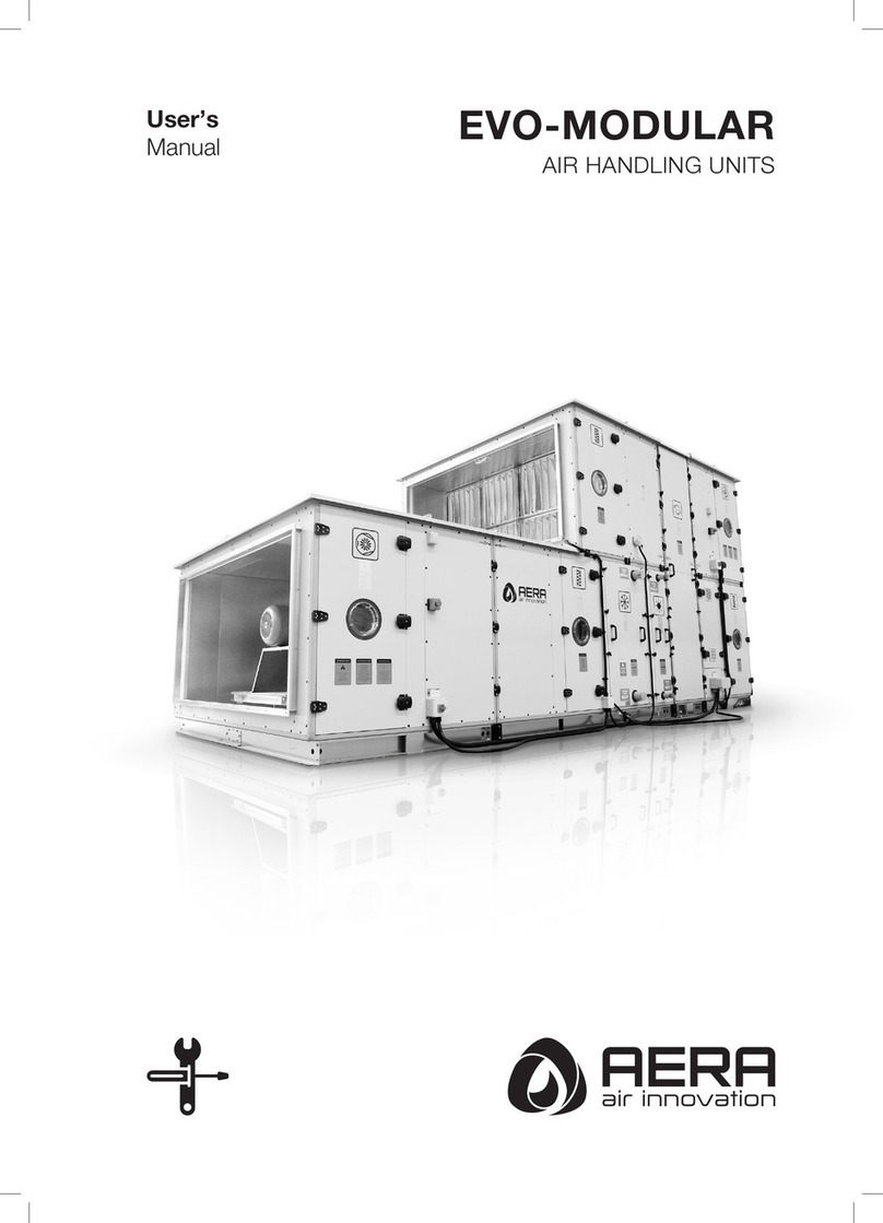
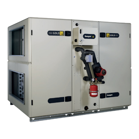
AERA EVO-MODULAR Series User manual

User’s
Manual EVO-MODULAR
AIR HANDLING UNITS

2
Contents
General Information.................................................3
Transport Installation ............................................5
Installation and Assembly......................................7
Installation of Components and Accessories........13
Electrical Connection..........................................18
Commissioning and Maintenance........................24

3
General Information
Foreword
General
EVO-M air handling units (AHUs) have been designed and manufactured in accordance with the CE machine directive. In
order to guarantee safe operation and use of the unit, please carefully read and observe the instructions in this document and
pay special attention to the warnings that apply to this unit. Any modifications in the design and/ or installation of the AHU
that are carried out without discussion with AERA and without advance written agreement will result in the loss of the right to
any warranty claims and any claim for injury to personnel as a result of these modifications. All work must be carried out by
sufficiently trained personnel.
Warnings and cautions
Warnings and Cautions appear at appropriate sections throughout this manual. Your personal safety and the proper operation
of this machine require that you follow them carefully. The constructor assumes no liability for installations or servicing performed
by unqualified personnel.
WARNING!: Indicates a potentially hazardous situation which, if not avoided, could result in death or serious injury.
CAUTION!: Indicates a potentially hazardous situation which, if not avoided, may result in minor or moderate injury. It may also
be used to alert against unsafe practices or for equipment or property-damage-only accidents.
Safety Considerations
To avoid death, injury, equipment or property damage, the following recommendations should be observed during equipment
operation:
1. The units are suitable for ambient air temperature between -20°C and +60°C and for air flow temperature between -20°C
and +40°C. Different conditions need written confirmation from the manufacturer.
2. Care should be taken by the user to prevent frost in coils. For ambient temperatures below 0C make sure that water inside
the cooling coil is removed during winter and a minimum of 25% Ethylene Glycol is added to heating water circuit.
3. Components - Some OEM products have specific manufacturer’s service instruction documents. These are delivered with
the Air Handling Unit. In this case, the indications in the OEM manual are valid and the service handbook in hand has only
general or complementary character for the relating components.
4. Liquid and gas storage -Maximum working pressure for all coils is 15bar. In case of coil connections to higher working
pressures, any warranty relating to coil tightness and personnel safety is excluded.
5. Tubing filled with mediums with very high or low working temperatures are to be insulated with suitable materials to avoid
burn or scald injuries caused by contact.
6. As fire prevention, fire dampers are to be provided where ducts cross firebreaks. Local fire prevention code is to be observed
carefully.
7. In case of external electrical heater usage, the operation of the heater and AHU must be interlocked and appropriate safety
components are used in the electrical circuit.
To avoid death, injury, equipment or property damage, the following recommendations should be observed during maintenance
and service visits:
1. The maximum allowable pressures for system leak testing on low and high pressure side are given in the chapter “Installation”.
Always provide a pressure regulator.
2. Disconnect the main power supply before any servicing on the unit.
3. The Air Handling Unit control system must guarantee that in case of breakdown or power interruption during maintenance
or repair work, the unforeseen start-up of a shut off unit is impossible.
4. Service work on the refrigeration system and the electrical system should be carried out only by qualified and experienced
personnel.
5. For inspection on the Air Handling Units and to avoid risks, the units surroundings are to be sufficiently lighted.
6. Heat exchangers filled with refrigerants must be serviced by specialized personnel. Waste disposal or recycling of dangerous
refrigerants must done in accordance with all international, national, and local regulations.
7. Where units are installed in areas with high temperature and/or high humidity, the risks of external condensation on the
casing must be considered.

4
General Information
Reception
On arrival, inspect the unit before signing the delivery note.
In case of visible damage: The consignee (or the site representative) must specify any damage on the delivery note, legibly sign
and date the delivery note, and the truck driver must countersign it. The consignee (or the site representative) must notify AERA.
And send a copy of the delivery note. The customer (or the site representative) should send a registered letter to the last carrier
within 3 days of delivery.
Warranty
Warranty is based on the general terms and conditions of the manufacturer. The warranty is void if the equipment is repaired
or modified without the written approval of the manufacturer, if the operating limits are exceeded or if the control system or the
electrical wiring is modified. Damage due to misuse, lack of maintenance or failure to comply with the manufacturer’s instructi-
ons or recommendations is not covered by the warranty obligation. If the user does not conform to the rules of this manual, it
may entail cancellation of warranty and liabilities by the manufacturer. Electrical motors are factory-tested and properly run when
leaving the factory. Any wiring faults on motors will cause damage for which AERA cannot be held responsible.
• The control package ( either bought from AERA as an accessory or sourced from a third party) must include frost protection
routines and components to prevent freezing damage of internal components (coils, heat recovery devices, humidifiers, …)
• Electrical connections may become un-tightened during transport. All electrical connections should be checked and re-ti-
ghten prior to commissioning. All electrical connections shall be made according to the wiring diagrams provided on the
components or in provided documents. Warranty is not valid if electrical components are not connected properly.
• When the unit use a medium (water/ refrigerant) with a temperature below than +2°C, The unit controls should be designed
in order to protect the exchanger against freezing. AERA cannot be held responsible for damages coming from freezing /
de-freezing operation.
• The warranty does not cover overheating due to wrong use or improper control of electric heaters.
• Dismantling or changing the units and/or components without AERA approval or assistance will invalidate the warranty.
• EVO-M units have been manufactured according to the selections and drawings provided with the order: AERA cannot be
held responsible for eventual non compliance to original specifications or specific requirements outside the order.
• In order to avoid fan motor overloading, the units shall be started with filters and other components fitted correctly, the du-
ctwork connected to the units and the access doors closed.
• Make sure the units work at design (Air flow/Pressure) conditions. The sound levels of the units can vary a lot depending of
the fan speed, the filter conditions or the actual duct pressure drops. Also, the given sound levels can be highly affected by
the installation method, the peripheral components, the ductwork and the acoustic characteristics of the building/room.
• The units must be controlled in order not to exceed the maximum or minimum differential pressure drops on plate heat ex-
changers indicated in the technical data sheets. The efficiency of the exchanger may drop significantly in higher / lower air
volumes and/or uneven air flows.
Maintenance Agreement
It is strongly recommended that you sign a maintenance contract with your local Service Agency. This contract provides regular
maintenance of your installation by a specialist in our equipment. Regular maintenance ensures that any malfunction is detected
and corrected in good time and minimizes the possibility that serious damage will occur. Finally, regular maintenance ensures
the maximum operating life of your equipment. We would remind you that failure to respect these installation and maintenance
instructions may result in immediate cancellation of the warranty.

5
Transport Installation
Storage and preventive maintenance
In case of external storage, units must be protected from adverse weather conditions. With internal and external storage, the
unit must also be protected against everyday damage. To avoid defects on the bearings, the fans and the motors must be
manually turned every month. If the units are not running for more than 18 months, the grease in the bearings must be changed.
When possible, all electrical equipment and fan belts should be removed and stored separately in dry atmosphere.
In case of long term storage, belts shall be removed in order to avoid stress on the bearings.
Off loading and handling
EVO-M units are supplied in section modules, or as a complete unit, in accordance with the relevant assembly drawings.
Any necessary use of force during unloading or movement of the units must only be applied via the unit base frame or the
shipping pallet.
The unit unloading and handling can be carried out easily with the use of a forklift or crane. For sections lighter than 1000 kg,
the unit can be lifted from the transport lugsb delivered separately.
Figure 1 - Crane operation procedure
1. Do not stand on the units. If this is unavoidable ensure a more
even weight distribution by the use of boards.
2. Use battens to prevent damage of the top and sides of the
units.
The forks must only be applied under the unit base frame and
not against it.
Note: The lift point should be as near as possible to the centre
of gravity. The centre of gravity of each section is located at the
centre of the unit length, with the exception of the fan sections
for which the centre of gravity is located towards the motors (see
Figures 2 and 3).
CAUTION! Never lift the units by the heat exchanger connections
or by any other projections. Do not tilt the fan module to avoid
possible impingement on the dampers.
Sections can be delivered provided of feet, pallets done by
wooden blocks positioned on each corner, base frame, base
frame base provide of fork holes.
In the case of section is provided of base frame without any fork
holes or without feet, insert the fork of the lift below the section
lifting it by a lever action. In this case, the bar must only bear against the base frame or profile (see Figure 2).
1 2 3
Figure 2 Figure 3

6
Transport Installation
With larger units, the use of several forklift may be required.
When rigging the unit by crane, follow these guidelines:
1. If lifting holes are provided on the unit base frame, sling spreader bars (see Figure 1, part 3).
2. If lifting holes are not provided, see Figure 1 part 4
3. If, as option, lifting points (eye bolts) are provides, crane belts can be connected directly to them.
4. The minimum rated lifting capacity (vertical) of each sling and spreader bar should be no less than the shipping weight
5. The unit must be lifted with care, avoiding shock load by lifting the unit slowly and evenly.
6. All lifting points in one axis of the unit must be used when offloading and moving the unit.
7. Slings are to be provided by the rigger and attached to all lifting points.
CAUTION! Loading, unloading and removal of single sections have to be carried out by employing means able to support the
unit weight indicated in the technical sheet. Ensure that the belts do not damage the top surface of the unit structure using
proper devices.
Note: Units fitted with base frames may be moved on roller trolleys or tubular rollers (see Figure 4).
CAUTION!
Supportıng and lifting under the cross beams or coils is prohibited. No horizantal transport devices must
be placed under this frame section such as pallet lifters or the forks of fork lift trucks.

7
Installation and Assembly
Installation and Assembly
You will find information regarding the assembly and installation of the unit.
This may only be carried out by specialists with the necessary knowledge of relevant accident
prevention regulations and other standard regulations relevant to health and safety in the workplace,
based on their training and experience.
The unit should be installed in such a way that it is accessible only to technical personnel with the
appropriate authorisation and training. The unit may only be assembled in accordance with the
application shown in the technical information supplied with the unit.
The units must not be stacked with other components that are not part of the unit.
This is only permissible if the necessary load-bearing capacity has been specially incorporated into
the units delivered from AERA
When connecting the duct it must be ensured that no foreign materials can enter the unit. If necessary,
a suitable wire mesh guard can be installed by the third party at the opening on the discharge/intake
side of the unit.
DAMAGE TO THE UNIT!
During installation of EVO-M units special care must be taken to ensure that no loads are applied to
the floor panels. During assembly work suitable measures should be taken to ensure that any loads
are spread across the bottom profiles (e.g. using grid walkways).
Installation
Installation location
The unit must be installed at a location that fulfils the following requirements:
– The substructure must be level and stable.
– The maximum deflection of the substructure may not exceed 4 mm per metre.
– In units where a condensate drain is installed, the height of the substructure must be at least the
same as to the required siphon height (see siphon).
– Make sure that no damage to the installation location or the environment can be caused by loose
components.
- In order to be able to remove fans, heat exchangers, droplet eliminators, etc. and also perform
servicing and maintenance, a minimum clearance of one unit width must be maintained on the
operating side.
- A minimum clearance of 600 mm between the rear of the unit and the wall must be maintained if
the internal dividing joint connectors cannot be used due to the unit configuration.
Heigh adjustment
Figure 5: Installation location

8
Installation and Assembly
Minimum clearances
• In order to be able to remove fans, heat exchangers, droplet
eliminators, etc. and also perform servicing and maintenance, a
minimum clearance of one unit width must be maintained on the
operating side.
• A minimum clearance of 600 mm between the rear of the unit and
the wall must be maintained if the internal dividing joint connectors
cannot be used due to the unit configuration.
Foundation construction for outdoor installation (weatherproof, roof frame)
NOTE!
EVO-M units for outside installation are not a substitution for roof! In compliance with prEN 13053 and
VDI 3803 it is not allowed to use surfaces of weatherproof units to support parts of a building or in a
similar way substitute a roof.
• Instructions for „Foundation construction for indoor installation“ on page 23 should be applied.
• If the unit has fresh air intake and discharge air make sure that the ducts are long enaugh so that
the discharge air is not by-passed to fresh air intake.
• Choose an installation location where the fresh air intake will not be facing the main wind
direction.
• In areas where there is a heavy amount of snowfall, the unit must be installed in a location where
its operation will not be affected by snow. A suitable height for the subconstruction must be
selected.
• If the unit is to be mounted on a roof, then the load-bearing capability of the roof and its
supporting structure must be checked. Consult a structural engineer if necessary.
• The roof edge below the unit, as well as ducts and other roof openings must be performed
waterproof by others.
• The roof frame must be insulated to prevent condensation. For information on installation, see
„Preparing installation of roof“ on page 30.
600 BB
Figure 6-1: Foundation construction on steel supports by others
Figure 6: Foundation construction on
steam beam by others

9
Installation and Assembly
NOTE
Particular care must be taken to ensure compliance with the precise dimensions of roof openings and
to ensure that the foundation is level.
Structure-borne sound attenuation
In order to reduce the transfer of vibrations from the unit to the supporting structure, anti-vibration
mounts and structure-borne sound attenuating mats must be installed.
– We recommend that the foundation is isolated from the unit using rubber plates, for example, where
the unit is installed on level ground and no special structure-borne sound isolation requirements
exist.
– We recommend the use of commercially available spring elements for ceiling mounting.
– For very special acoustic requirements please consult an acoustics engineer to select the most
suitable structure-borne sound attenuation method.
Assembling the unit
NOTE
For detailed information, please refer only to the documentation enclosed with the unit. Data sheet,
installation instructions, small parts and accessories supplied loose can be found in the unit part
specified in the parts list.
DAMAGE TO THE UNIT!
Fittings/attachments etc. not provided by the manufacturer that could cause a leak must not be
mounted on the walls or frame of the unit. The unit’s operability must be maintained.

10
Installation and Assembly
Removing transportation lugs/device/locks
• All transportation lugs/devices/locks marked yellow on and in the unit must be removed prior to
assembly.
• Remove the transportation locks on the fan.
• The transportation lugs on the roof must be removed.
• Remove the screws on the end panels and secure the supplied M8 x 70 screw.
• Remove the lug, screw and bushing at the dividing joint, then secure the supplied M8 x 30 screw.
NOTE!
Because of danger of collision with transport lugs - externally mounted dampers/louvres, flexible
connections are partially supplied loose. These components are field-mounted and sealed by others.
NOTE
Transportation lugs/device must not be used to suspend the units on a permanent basis.
Transportation lugs/device may be used only once.
Figure 6-2: Transport lugs – roof, end wall and
dividing joint

11
Installation and Assembly
Installation of individual modules
To assemble individual modules (dividing joint) proceed as follows:
• Do not forget to attach the sealing seal between the two modules while assembling the modules.
Once you have connected the modules, make sure you stick the two modules with silicone.
DAMAGE TO THE UNIT!
Do not attach tensioning belts/hoisting devices to heat exchanger connections, condensate drains
and door handles or use these to pull or push the equipment!
• Position the unit parts as close to one another as possible prior to assembly. Only use the unit
base frame to pull the individual components together. Units that do not have a base frame must
be pulled together with tensioning belts.
These must be positioned round the profiles in the base or roof area.
Figure 6-3: Installing individual modules
Figure 6-4: Unit with base frame Figure 6-5: Unit without base frame
max. 80 mm

12
Installation and Assembly
• If the rear of the unit is not accessible, screw the interior dividing joint connectors in the
corner together.
NOTE
An additional dividing joint connector is provided in the middle of the profile (internally)
where the internal unit width or height is 1240 mm or more – this must also be screwed
tight.
• Seal pipe and cable ducts to prevent air leakage and condensation using Polyurethane
foam, or similar insulation metarial (not included in EVO-M delivery scope).
Additional measure for double-deck/side by side units
• Connect both unit parts using the provided plates.
Additional measure for hygiene units
• Clean and seal all internal dividing joint grooves in the floor area.
The sealant is included in the scope of delivery for hygiene units.
Fig. 6-6: Internal view
Figure 6-7: Pipe duct
Figure 6-8: Connecting unit parts
Figure 6-9: Dividing joints.

13
Installation of Components and Accessories
Installation of Components and Accessories
In line with the connection of heat exchangers, humidifiers etc., the coil connection may only be
carried out by specialists with the necessary knowledge of relevant accident prevention regulations
and other standard regulations relevant to health and safety in the workplace, based on their training
and experience.
DAMAGE TO THE UNIT!
When mounting EVO-M units care must be taken to ensure that no loads are applied to the floor
panels. During installation work suitable measures should be taken to ensure that any loads are spread
across the bottom profiles (e.g. using grid walkways).
Prerequisites
• Check the unit for external damage and check whether it has been properly assembled and
anchored.
• Check whether anti-vibration and structure-borne sound attenuating mats have been provided.
This means that either:
– the foundation has been isolated from the unit using rubber plates (for example) where the unit
is installed on level ground and no special structure-borne sound isolation requirements exist;
– or, in the case of ceiling mounting, commercially available spring elements have been used;
– or, where very special acoustic requirements exist, an acoustics engineer has been consulted
when selecting the most suitable structure-borne sound attenuation method.
• Before you start with the coil connection, check the following:
– Drain valves must be installed at all low points in the water system to ensure that the water
circuit can be fully drained in order to carry out maintenance or repairs.
– A water drain with shut-off valve must be installed in order to drain the unit’s water system.
– Air vents must be installed at all the high points of the water system at easily accessible locations.
• Ensure that the piping system is flushed through until it is clean by others and a cleaning record
compiled.
Installation of air control and air conveying components
In order to prevent the transmission of structure-borne sound, a tension-free connection between air
ducts and the unit must be made using elastic connectors or structure-borne sound attenuators (also
compare „Structure-borne sound attenuation“ on page 26).
If you are connecting air ducts to the units via flexible connectors, the installation
length of the connectors must be less than their extended length.
Installation of air handling components with coil connection
Recommendations on water quality for heat exchangers that operate using low pressure hot water
(LPHW) and chilled water:
A good water quality – e.g. salt and lime-free drinking water – increases the lifetime and efficiency of
the heat exchanger.
• Check the limiting values shown in the table annually to prevent damage to the hydraulic system
and its components. If necessary inhibitors must be added.

14
Installation of Components and Accessories
Description Symbol Values Effects in event of deviation
Hydrogen ion
concentration
pH 7.5 − 9 < 7
> 9
Corrosion
Fouling
Calcium and
magnesium
content
Hardness
(Ca/Mg)
4 − 8.5 °D > 8.5 Fouling
Chloride ions Cl–< 50 ppm Corrosion
Iron ions Fe³+< 0.5 ppm Corrosion
Magnesium ions Mg²+< 0.05 ppm Corrosion
Carbon dioxide CO2< 10 ppm Corrosion
Hydrogen sulphate H2S < 50 ppb Corrosion
Oxygen O2< 0.1 ppm Corrosion
Chlorine Cl2< 0.5 ppm Corrosion
Ammonia NH3< 0.5 ppm Corrosion
Ratio of carbons/
sulphates
HCO3²-/SO4²-> 1 < 1 Corrosion
1/1.78 °D = 1 °Fr with 1 °Fr = 10 g CaCO3/m³
ppm = parts per million (mg/l)
ppb = parts per billion (μg/l)
Note
These limiting values are only basic
information about the water quality
and do not form any basis for a
guarantee!
Installation of air handling components for cooling/heating
DAMAGE TO THE UNIT!
When connecting the heat exchanger, counter force must be applied using pliers to
prevent damage.
The connections to the heat exchanger by others must always be tension-free.
Mechanical and static loads must not be applied to the connecting piece.
The heat exchanger must be connected in accordance with the counter flow principle (air
and water heat exchanger flow in opposite directions).
• Protect the surfaces of the fins in the heat exchanger from damage.
• Connect pipe system by others to the water inlet and outlet. The inlet and outlet coil
connections are marked using adhesive labels.
• Insulate pipes by others.

15
Installation of Components and Accessories
In addition, for air handling components that perform cooling function:
• Insulate coil connections and pipes once the installation has been carried out to prevent the
formation of condensation water.
Condensate water that is formed accumulates in the stainless steel condensate tray and is
drained via a drain spigot mounted on the condensate tray.
• Install a siphon (see „Connecting siphon and water drains“ on page 41).
In addition, for units with fresh-air or mixed-air operation:
DAMAGE TO THE UNIT!
The heat exchanger in the unit must be protected from the formation of ice and freezing at ambient
temperatures below the freezing point.
Use antifreeze in the water circuit if necessary.
NOTE
Glycol may be used providing that it does not exceed 50 % of the overall volume.
A higher quantity can cause operational faults.
Installation of evaporator/condenser components
ENVIRONMENTAL DAMAGE!
Dispose of any liquid spills (refrigerant) in an environmentally sustainable manner in accordance with
the locally applicable laws and regulations.
• Open and use the service connections using only special tools and fittings.
The units are filled with protective gas that audibly discharges when the connection caps are
removed.
Installation of liquid-coupled heat exchangers
Compare „Installation of air handling components for cooling/heating“ on page 39.

16
Installation of Components and Accessories
Installation of humidifying equipment
Refer to the accompanying documentation for information on assembly and installation.
Also observe the German Drinking Water Act (Trinkwasserverordnung – TWVo).
Recommended “Guide values for the quality of water circulating in the spray humidifier
(air washer)” (in accordance with: VDI 3803 “HVAC systems. Constructional and technical
requirements”, October 2002, Appendix A, Table A1):
Normal
climatic
requirements
IT rooms Sterile rooms
and
cleanrooms
pH value 7 ... 8.5
Total salt content g/m³ < 800 < 250 < 100
Electrical conductivity
(at reference
temperature 20 °C)
mS/m
μS/cm
< 100
< 1000
< 30
< 300
< 12
< 120
Calcium (Ca2+) mol/m³
g/m³
> 0.5
> 20
-
-
Carbonate hardness °dH < 4 -
Carbonate hardness
with hardness
stabilisation
°dH < 20 -
Chloride (Cl-) mol/m³
g/m³
< 5
< 180
-
-
-
-
Sulphate (SO42-) mol/m³
g/m³
< 3
< 290
-
-
-
-
KMnO4consumption g/m³ < 50 < 20 < 10
Germ count organisms/ml < 1000 < 100 < 10
Legionella bacteria organisms/ml < 1
NOTE
We recommend that you repeat the water analysis when installing a water softening sys-
tem. The total salt content must not exceed 250 g/m³. The electrical conductivity must
not exceed 300 μS.
DAMAGE TO THE UNIT!
Honeycomb humidifiers must not be operated with fully desalinated water.
Connecting siphon and water drains
NOTE
The equipment must not be connected directly to the waste water system!
Fill the siphon with water before commissioning and also following longer periods of
downtime.

17
Installation of Components and Accessories
2H
H
1,5 H
Figure 7: Siphon: overpressure in unit
Figure 7-1: Siphon: underpressure in unit
Figure 7-2: A siphon must be connected to each condensate drain or overflow pipe. Several discharge pipes must
not be routed to one shared siphon (* drain blocked).
2,5 H
1,5 H H
The hydraulic seal in the siphon H must be greater than the maximum
overpressure or underpressure (mm WC) in the unit (1 mm WC = 10
Pa).
The dimensioning is performed using the equation below:
H(mmWC) = Unit over-/underpressure(Pa)
10
The height difference between the water drain and hydraulic seal must
also correspond to the dimension H (mm WC).
• Connect the siphon to the waste water system as shown in the
illustration.
NOTE ON RISK OF FROST.
If there is a risk of frost, the discharge pipe must
be insulated and kept warm using a heating cable,
for example.
NOTE
Underpressure and overpressure siphons must be connected to separate collecting pipes (Refer
to fig. 7-2).
Installation of accessories
Refer to the relevant documentation provided for descriptions of the assembly and installation of
accessories or accessory parts by others.

18
Electrical Connection
Electrical Connection
The electrical connection may only be carried out by specialists with the necessary know-
ledge of relevant accident prevention regulations and other standard regulations relevant
to health and safety in the workplace, based on their training and experience.
Take protective measures!
During installation and connection of the unit, additional protective measures must be
taken into account when setting up low voltage equipment in accordance with the EC
directive and the regulations of the local utility provider. Ensure earthing/grounding and
potential equalisation is provided for the unit and all connected components and indivi-
dual units.
It must be ensured in a demonstrable way that all individual units are connected in a elect-
roconductive manner. (Usually potential equalisation is provided using connection screws
and bolts). The entire unit or system must be connected to the same potential.
Passive switch contacts in explosion protected units may only be used in intrinsically safe
electric circuits.
ELECTRICAL HAZARD!
All power supply connections must be switched off and be voltage-free and secured
against unintentional switching on. Earth and short-circuit them and cover over any neigh-
bouring electrically conducting components or block them off. Failure to do so may lead
to serious injury or death.
NOTE
The cable installation must be carried out in accordance with the enclosed wiring diagram
of the unit and nationally applicable standards and guidelines. Only one separate mains
power cable should be used. Never connect other units to this mains power cable.
Prerequisites
• Carry out a full visual inspection of the entire unit and installed components.
• Before you start with the electrical connection, check the following:
– The characteristics of the mains power supply must satisfy EN 60204-1 regula-
tions and the power requirements of the unit.
– The size of the backup fuse must be determined by the specialist electricalte-
chnician responsible based on the unit’s power rating.
– The motors must be able to operate at their nominal capacity where the input
voltage with nominal frequency is between 95 % and 105 % of the nominal
voltage.
Cable routing and grommets by others
• The installation of cable grommets and the routing of cables near doors, panels with
sash fasteners, panel connections and cover strips must be avoided.
• Screw connections and grommets must not cause any leaks.
• The connecting cables within the fan components must be long enough to allow the
motor to be moved without difficulty (in order to re-tension the V-belt, for example).
Connecting the unit
Each subassembly with an electrical connection must be earthed separately.
Visual inspection of the
mechanics

19
Electrical Connection
Motor protection
Motor protection with PTC resistor sensors
The AC motors contain between two and six PTC resistor sensors connected in series,
depending on the motor size and type. The PTC resistor sensors are embedded in the
windings of the motors in a way that optimises recording of the winding temperature. PTC
resistor sensors are temperature-dependent semiconductor resistors.
When the maximum permissible winding temperature of 135 °C is reached, the resistance
value increases rapidly. This response, combined with full motor protection electronics,
causes the motors to switch off.
NOTE
Unlike thermal contacts, PTC resistor sensors are not subject to wear. They provide a high
degree of operating safety as they are shock-resistant, vacuumresistant and not sensitive
to pressure.
DAMAGE TO THE UNIT!
The separate sensor with external leads must not be connected to voltage as this would
damage it beyond repair. Measuring voltages greater than 5 V are not permitted.
Connect the sensor only to full motor protection tripping devices.
INDUCTION EFFECTS
We recommend the use of shielded cables (such as JY (st) Y, 2 x 2 x 0.5) to prevent the
effects of induction on the PTC resistor measuring circuit. Connect the shielding on one
side with the potential equalisation (PE).
Full motor protection electronics
For motor protection we recommend our EVO-M 912.MVS 1.0 full motor protection trip-
ping devices. They have been specially harmonised with the PTC resistor sensors used
in the motors. As operation of the full motor protection electronics is based on the clo-
sed-circuit current principle they are intrinsically safe. A locking shutdown after a fault and
restart following power failure generally occur in conjunction with EVO-M 912.MVS 1.0 full
motor protection tripping devices.
The electronic full motor protection tripping devices switch the motors off where
the following occur:
– Overloading
– Ambient temperatures exceed permissible limits
– The rotor is locked
– Insufficient cooling
– Short circuit in winding
– Wire breakage and loose contacts in the measuring leads
+135
C
Resistance R
Temperature T
Operating point of
tripping device

20
Electrical Connection
In the case of a high start-up frequency, intermittent operation and switching rate, and
to provide optimum protection against 2-phase running, we recommend that motors
are protected by thermal overcurrent relays/motor circuit breakers, in addition to PTC
resistors.
In the event of a shutdown after a fault check whether this is due to one of the
aforementioned causes.
Motor protection with thermal contact
Thermal contacts are temperature-dependent operation elements that automatically
monitor the winding temperature of a motor. Compared to thermal tripping devices and
motor circuit breakers, these devices provide more effective protection under the following
circumstances when installed in the motor winding:
– Insufficient cooling
– Increased ambient temperature
– Extreme speed reduction during control and regulation operations
– Shutdown of the motor in the event of control voltage failure on the line side
– Faulty contacts and cable breakages in the control circuit.
The thermal contact opens when the permissible temperature of the winding is exceeded.
This interrupts the control signal loop of a control unit, for example.
The fan protection drops out and disconnects the motor from the mains.
The motor protection is intrinsically safe.
Connecting electric motors
In order for the unit to operate properly it is important to connect it with a righthand
rotating field.
• Check the rotating field if necessary with a rotating field meter.
DAMAGE TO THE UNIT!
Correct assignment of the phase sequence to the specified rotational direction must be
checked before the motor is connected. If the wrong connection is made the motor/fan
may be damaged.
The terminals of AC motors are labelled in such a way that the alphabetical sequence
of the terminal designation U1, V1, W1 corresponds with the temporal sequence of the
phases L1, L2, L3 (with clockwise rotation).
The rotational direction can be reversed by exchanging two connecting cables:
– Exchange the connecting cables, e.g. U1 and V1
– Y connection: Exchange the connecting cables, e.g. U1 and V1
– Δ connection: Exchange the connecting cables, e.g. U2 and V2
– Speed 1: Exchange the connecting cables, e.g. 1U and 1V
– Speed 2: Exchange the connecting cables, e.g. 2U and 2V
– Speed 3: Exchange the connecting cables, e.g. 3U and 3V
• Make sure that the supply voltage with mains frequency is between 95 % and 105 %
of the rated voltage. Only then can the motors to operate at their rated output, otherwise
they may be damaged.
To make the connection, proceed as follows:
• Connect the unit according to the wiring diagrams.
Extended motor protection
Shutdown after fault
Single-phase electric motors
with direct on-line starting:
Single-speed electric motors
with Y/Δ starting:
Multi-speed electric motors:
Voltage fluctuations
This manual suits for next models
1
Table of contents
Other AERA Air Handler manuals
Popular Air Handler manuals by other brands
IBC
IBC AHU Series Quick Reference Installation Guide
Reznor
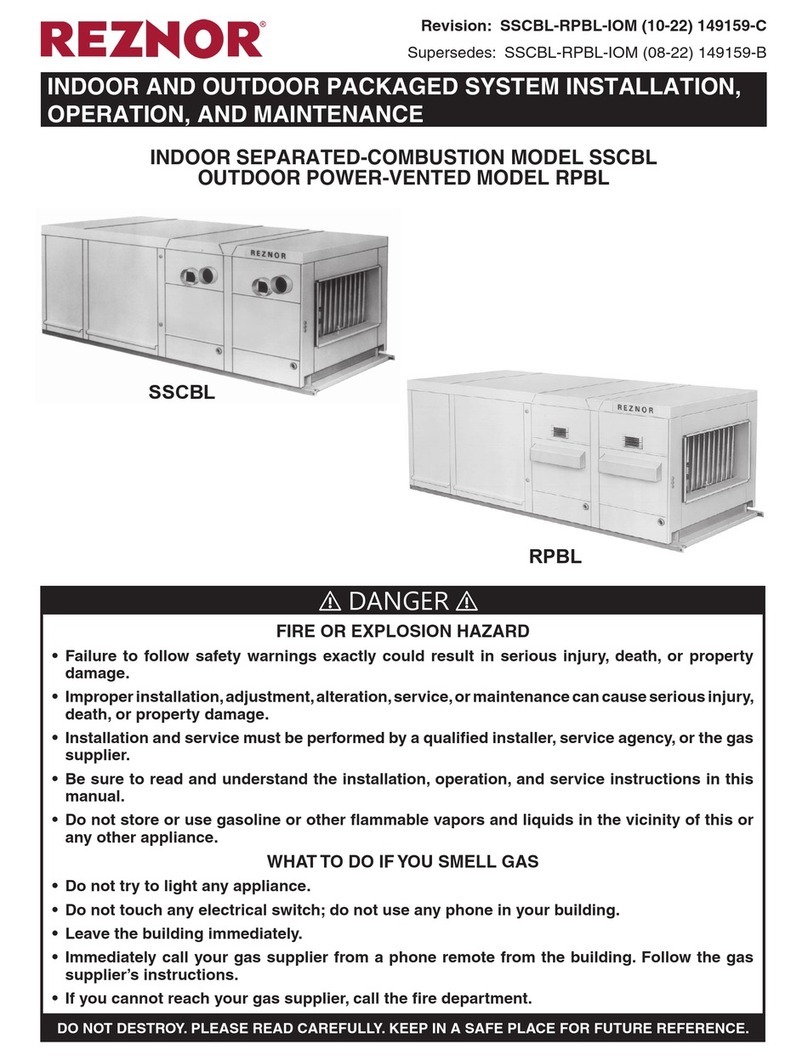
Reznor SSCBL Installation, operation and maintenance

Zoning
Zoning Zity Technical and installation manual
BLAUBERG
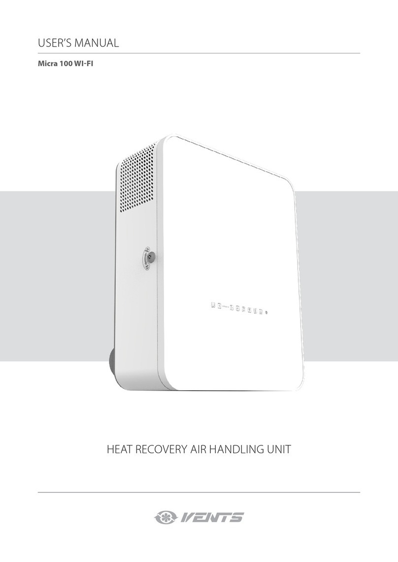
BLAUBERG Micra 100 WI-FI user manual
Vents
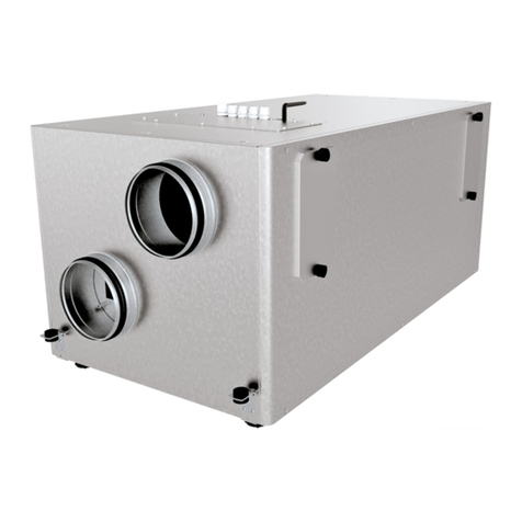
Vents VUE 300 HB EC user manual
IV Produkt
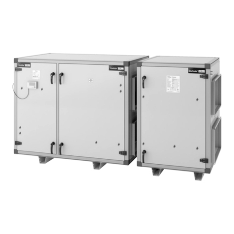
IV Produkt Envistar Compact Series Operation and maintenance manual
VTS Medical Systems
VTS Medical Systems VOLCANO VR Mini Technical documentation

Salda
Salda VEKA W Technical data
Goodman
Goodman MBVC 1 Series installation instructions

Puro
Puro Fighter FR-16 manual
ClimateCraft
ClimateCraft DHII-007 Installation, operation and maintenance manual

Xvent
Xvent Atacama 2 instruction manual
