Otodata TM7530HP Operating and maintenance manual

Installation Procedure
TM7530HP
Tank Monitor
and Hydrostatic
Pressure Sensor
all
ation Proce
d
ur
e
M
753
0
HP
a
nk M
o
nit
o
r
nd
H
y
d
rostatic
re
ss
u
r
e
S
e
ns
or
Do not
pressure wash
WARNING Substitution of components may impair intrinsic safety.
For outdoor use only. Explosion Hazard - Batteries must only be
changed in an area free of ignitable concentrations. Do not open when
an explosive atmosphere is present. Potential electrostatic charging
hazard - wipe only with a damp cloth.
BATTERY REPLACEMENT Battery replacement must only be performed
by OTODATA Wireless Network Inc. factory to maintain intrinsic safety
protection of the TM7530HP. Cover shall not be opened when an explosive
atmosphere is present.
IMPORTANT It is critical in all
installations to ensure monitors’ antenna
is positioned vertically. This will achieve
optimal signal strength, ensuring that
you receive data in a timely manner and
prolong the battery life of the monitor.
PLEASE TAKE A MOMENT TO CAREFULLY READ
THE INSTALLATION INSTRUCTIONS INCLUDED
WITH YOUR MONITORS, AND ENSURE YOU
UNDERSTAND AND RESPECT LOCAL
REGULATIONS.
GRA-0034 - EN Rev: 001


Years ago we saw an opportunity
to innovate in an industry where
modernization happens very slowly
and costs associated to large-scale
implementation made expansion
and growth unaordable for a
large portion of the industry.
We’re changing that.
Otodata has been a key player in the tank
monitoring industry for over ten years.
Our goal has always been to produce a
monitor with very low cost of ownership -
making large-scale implementation aordable
for all fuel resellers.
We're proud to say we design, develop,
manufacture and sell our award-winning tank
monitors, management software, and mobile
app to businesses all over North America.
All our monitors provide precise, extremely
reliable data, carry industry leading warranties,
and are compatible with all read-ready dial
equipped tanks.
Thank you for your interest in our monitors.
Sincerely,
The Otodata Team

CANADA
INTERNATIONAL
PLAINS & NORTHEAST
SOUTH
WEST
WEST
MEXICO
SUPPORT
1-514-673-0244 | 1-844-763-3344 (Toll-free)
support@otodatatankmonitors.com
EMERGENCY SUPPORT
1-833-529-9499
Available 24 hours, 7 days a week.

1
IONAL
Input
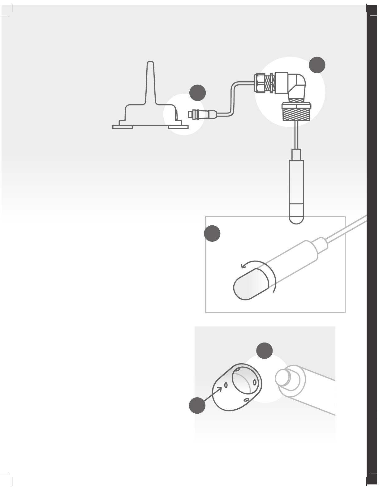
Hydrostatic Pressure transducer with dierential to
atmospheric pressure 0.5-4.5V non-ratiometric
Reporting & Outputs
Reporting Tank level (5% variation)
Low battery
High/Excessive draw
Fill Detection
Temperature
Data Interface API
Email (to supplier and/or
consumer)
Raw data
Online dashboard
Client mobile app
Automated Testing Network status
Lead sensor status
Battery status
Electrical Specifications
Battery Pack Hybrid LTC 3.6 VDC 7.2 VDC
Radio Specifications
Technologies 4G, LTE CAT1, CATM, NB IOT, 3G
Dual SIM
Bluetooth
Environmental Specifications
Operating & storage
temp. range -40˚C to 60˚C -40˚F to 140˚F
Relative humidity range 0% to 100%
Enclosure rating IP68
Warranty 5+ years
Option GPS (mobile tank)
Certifications
Monitors are third-party QPS Evaluation Services Inc.
Certified for use in hazardous locations
United States
Ratings Class I, Division 2, Groups
C-D, T3 Class I, Zone 2, AEx ic
[ia Ga] IIB T3 Gc
Standards applied:
UL 60079-0:2019 - UL 60079-11:2013
Canada
Ratings Class I, Division 2, Groups
C-D, T3 Ex ic [ia Ga] IIB T3 Gc
Standards applied:
CSA 60079-0:19 - CSA 60079-11:14
Dimensions
Height 14 cm 5.5 in
Width 14 cm 5.5 in
Depth 9.5 cm 3.5 in
Applications
Level Measurement in Bio-Fuels
Monitoring of Gasoline and Diesel Fuel Tanks
Level Measurements in Ballast Tanks
Level Measurements in Oil Tanks
Monitoring of Contain Coolant for Diesel Engines
Level Measurement in AdBlue Tanks
Level Measurement in Kerosene
Characteristics
MEAS TE pressure cell, 0.5% F.S.
Survives Harsh Environments
EMI/RFI Protection
Custom level ranges from 1.5 to 16m
PUR cable lengths
Order
Otodata Monitor with Hydrostatic Pressure Sensor
(Range 0-1.5ft) TM7530HP-001
Otodata Monitor with Hydrostatic Pressure Sensor
(Range 0-4.5ft) TM7530HP-002
Otodata Monitor with Hydrostatic Pressure Sensor
(Range 0-6.5ft) TM7530HP-003
Otodata Monitor with Hydrostatic Pressure Sensor
(Range 0-12.5ft) TM7530HP-005
Otodata Monitor with Hydrostatic Pressure Sensor
(Range 0-25ft) TM7530HP-009
Otodata Monitor with Hydrostatic Pressure Sensor
(Range 0-32ft) TM7530HP-011
Otodata Monitor with Hydrostatic Pressure Sensor
(Range 0-52ft) TM7530HP-017
This device complies with part 15 of the FCC Rules. Changes or modifications not expressly approved by the party responsible for compliance could void the user's authority to operate the equipment. Operation is subject to the following two
conditions: (1) This device may not cause harmful interference, and (2) this device must accept any interference received, including interference that may cause undesired operation. This device is compliant with Industry Canada's RSS standards for
license-exempt radio apparatuses. Authorized use depends on the following two conditions: (1) the device must not create radio interference, and (2) the device user must accept all radio interference, even if this interference could potentially impair
its functioning. This equipment has been tested and found to comply with the limits for a Class B digital device, pursuant to part 15 of the FCC Rules. These limits are designed to provide reasonable protection against harmful interference in a
residential installation. This equipment generates, uses and can radiate radio frequency energy and, if not installed and used in accordance with the instructions, may cause harmful interference to radio communications. However, there is no guarantee
that interference will not occur in a particular installation. If this equipment does cause harmful interference to radio or television reception, which can be determined by turning the equipment o and on, the user is encouraged to try to correct the
interference by one or more of the following measures: —Reorient or relocate the receiving antenna. —Increase the separation between the equipment and receiver. —Connect the equipment into an outlet on a circuit dierent from that to which the
receiver is connected. —Consult the dealer or an experienced radio/TV technician for help.
Specifications Fuel, lubricants, oil and more. A tank
monitor to suit your corporate needs.

2
Choose the most convenient port
on your tank, but not the one
that is normally used for filling.
This installation is intended to be
permanent or not often removed.
See following page for more
information.
Clean around the tank’s port to
avoid contamination of fuel;
Remove any rust or dirt on the plug
or fitting threads.
Communicator
Connector
SS304
Polypropylene
Reducer 2” NPT
PUR Jacketed Cable
Nylon 6/6 with TPE
Sealing Cord Grip
Device Anatomy
Ideal position
Start clean
Polypropylene
Elbow 1” NPT
Black Nylon
Cover Tip
Sensor/Transducer
SS304

3
1
2
3
4
5
6
Maximizing Monitor Performance
1 2
3
Not Optimal.
Installing a monitor in position 1, 2 or 3 can cause
impediments to signal transmission which can result
in inaccurate readings and premature drainage of a
monitor’s battery.
4 5
6
Optimal Position.
Installing a monitor is position 4, 5 or 6 will ensure
maximum signal strength which will conserve battery
life and provide accurate readings.
Too close to wall. Can cause signal
interference.
Monitor installed too horizontally.
Can cause signal interference.
Mounted vertically, top of tank, far
from walls. Maximizes signal strength.
Mounted vertically, side of tank,
far from walls. Maximizes signal
strength. Suggested wall mount
bracket: ACWMB1.

4
Step 1 Unplug your monitor
a. Unplug the cable from the communicator by carefully
turning the connector’s front holding nut counter-clockwise.
Insert the sensor into the tank
b. Loosen the cover nut and remove the cord grip from
the elbow to allow the cable to move;
c. Then push the cable through the elbow until most of
the cable is hanging with the sensor, ensuring the sensor will
touch the bottom when inserted in the tank;
d. Gently pull/tug the cable to straighten it. Please DO NOT
pull from the sensor or connector;
e. Slowly insert the sensor into the tank until it is skimming
the bottom;
f. Slide reducer, elbow and cord grip through the cable
until touching the bung hole.
f
e
Installation Instructions
Safety
5 FEET MINIMUM (125CM)
FROM T-VENT
IMPORTANT ALWAYS FOLLOW YOUR
LOCAL REGULATIONS AND STANDARDS.
Consult with certified personnel to ensure
your installation is compliant.
Mounting fittings, such as elbow fitting,
are not part of the certification for model
TM7530HP. Final installation shall be
subjected to acceptance by the Local
Authority Having Juristiction.

5
Step 2 Adjust your cable length
g. Thread fittings into bung hole of tank and tighten with
a wrench. Note: Be careful not to over-tighten as the
plastic fittings can get damaged;
h. On the final torque, ensure the cable is facing towards
the communicator;
i. Carefully push the cable through the elbow to ensure
you leave a little extra cable inside (3-4 inches for tanks
shorter than 6 feet. 5-10 inches for tanks taller than 6 feet);
Note: DO NOT leave too much cable inside as it could skew
level readings. Guidelines above must be followed closely.
Step 3 Secure lead in place
j. Tighten the cover nut at the elbow to fix cable in place.
Step 4 Connect
k. Connect cable to communicator.
Preparation
DO NOT apply Teflon
tape on the front nut
of the cord grip.
DO apply Teflon tape
on the NPT connections.
i

6
Device Maintenance
When required, clean the
sensor in order to remove
any accumulated dirt,
sludge, gunk or debris.
Step 1 Remove sensor from tank
a. Disconnect the cable from the
communicator and carefully remove
the sensor from the tank.
b. Avoid disconnecting or loosening any of
the parts which secure the cable in place.
Loosening these joints can cause the cable
to shift in length. This can eect the
accuracy of the reading.
Step 2 Disassemble sensor and clean
c. Once removed, rinse sensor thoroughly
under running water.
d. When exterior of sensor is clean, twist
the tip of the sensor counter-clockwise
to unscrew.
e. Rinse the inside of the tip cover thoroughly
ensuring all dirt, grease or debris has been
washed away.
f. Ensure the small orifices on the tip cover are
also thoroughly cleaned so fluid can filter
through freely.
Step 3 Reassemble and install sensor
g. Towel or air dry sensor shaft and tip
thoroughly and re-attach.
Inner tip is sensitive. Avoid touching.
h. Install sensor in tank.
If needed: add Teflon paste or tape to the
bushing fitting. Remember to roll the cable
to avoid damage while screwing in.
i. Reconnect cable to transmitter.
d
e
f
b
a

7
Members can purchase monitors and accessories like gauges, leads,
mounting equipment and more via our online store.
Members can watch
step-by-step installation
videos and shop online
Sign up free today
otodatatankmonitors.com/membership

IMPORTANT
Please take a moment to carefully read the installation
instructions included with your monitors, and ensure you
understand and respect local regulations.
ABOVE-GROUND TANKS UNDERGROUND TANKS
Do not install monitors
under lids.
Plastic lid suggested.
Metal lids will obstruct signal.
Reading installation instructions will ensure maximum
monitoring performance on all your tanks and installations.
Table of contents