Otterbine/Barebo AirFlo 3 User manual

Manual
P
P
N: 75-0109
R
R
ev 05
O
A
I
n
O
tter
b
A
irFl
o
n
stall
b
ine
B
o
3 D
i
atio
n
B
are
b
i
ffus
e
n
Ma
n
b
o I
n
e
d A
e
n
ual
n
c.
e
rati
o
o
n

Otterbine Barebo Inc.
2 75-0109 AirFlo 3 www.otterbine.com
1-800-AER8TER
AIRF LO 3 EQUIPMENT
A. Unpack and Inspect
1. Inspect the AirFlo 3 System received and report any shipping damage to the carrier which delivered your Otterbine
aeration system.
B. Check Equipment Received is as Specified
1. Compressor Cabinet: Constructed of 304 Stainless Steel this houses the air compressors, valve manifolds, ventilation
fans and the main switch. Check the nameplate to verify you have received the correct AirFlo 3 compressor cabinet and
voltage rating for the system ordered. (See Illustration on Page 3)
C. Tubing
1. Verify that you have received the correct type and quantities of tubing kits, poly unweighted and/or weighted, for your
application.
D. Air Diffuser Manifold Base
1. Check the correct quantity and types, single or dual disc, Diffuser Manifold Base/s were received. (See Page 8)
For proper warranty consideration register on line: www.otterbine.com/warrantyform or return warranty registration
card by mail to OTTERBINE within fifteen (15) days of receipt by the Purchaser at retail in order to avoid delays:
INSTALLATION TOOLS AND EQUIPMENT
A. Basic Installation Tools and Materials Required for Installation
1. All-purpose gravel: For weighting the Disc Diffuser Manifold Bases, approximately 20lbs. per Diffuser Manifold Bases.
2. 100’ lengths of 1/8” Nylon Rope for installing Disc Diffuser Manifold Bases.
3. Shovel and Pick, Level, possibly a boat or raft.
4. Hand Tools: 5/16” Nut Driver or Wrench, Adjustable Wrench, Pump Pliers, Tubing Cutter or Utility Knife.
COMPRESSOR CABINET INSTALLATION
A. Placement
1. Select a location for the AirFlo 3 compressor cabinet where it will not be exposed to flooding or corrosive chemicals.
2. Allow a minimum of 6” (15 cm) clearance on all sides of the AirFlo 3 cabinet to any walls or other obstructions.
3. To provide flexibility for mounting the AirFlo 3 compressor cabinet four (4) mounting holes are provided on the bottom
of the cabinet which will accept up to a 1/2" or M14 size bolt. The AirFlo 3 cabinet should be placed directly on a level
prepared gravel or concrete base, or equipment pad.
TOP VIEW
MOUNTING
BOLT HOLE
PATTERN

Otterbine Barebo Inc.
3 75-0109 AirFlo 3 www.otterbine.com
1-800-AER8TER
ELECTRICAL INSTALLATION
ALL ELECTRICAL WORK MUST BE PERFORMED BY A QUALIFIED LICENSED ELECTRICIAN
AND CONFORM WITH ALL APPLICABLE ELECTRICAL SAFETY CODES
Toustravaux électriques doivent êtreeffectués par un électricienprofessionnel qualifié
et conforme àtous les codes applicables sécurité électrique
ALWAYS SWITCH OFF/DISCONNECT ALL EQUIPMENT IN THE WATER
BEFORE SERVICING OR PERFORMING ANY MAINTENANCE
Toujours éteindre l'équipement dans l'eau avant entretien ou de tout entretien
CAUTION: GFCI PROTECTION REQUIRED
If GFCI protection is not used, serious or FATAL electrical shock may occur
ATTENTION: GFCI/RCD de protection est nécessaire
Graves ou mortelles choc électrique peut se produire s'il n'est pas utilisé
WARNING: RISK OF ELECTRIC SHOCK
The AirFlo 3 must be connected to a grounded, metallic, permanent wiring system
Ground the compressor cabinet to the ground wire lead provided back to the service
using a copper conductor at least the size of the circuit conductors supplying the cabinet.
A. Branch Circuit Sizing (All valves must be in the open position before initial operation)
1. The branch circuit feeding the Otterbine AirFlo 3 must be sized in accordance with all applicable codes and must
provide GFCI (Ground Fault Circuit Interruption)/RCD (Residual Current Device) and short circuit protection. Refer to
the nameplate label on the compressor cabinet above the electrical connection box for voltage and current requirements.
The on/off switch provided with the AirFlo 3 does not provide personal (GFCI / RCD) electrical shock protection.
B. Electrical Connection
1. The AirFlo 3 is not considered to be portable
equipment and therefore flexible cord shall
not be used to connect the cabinet to the
power source. The electrical connection must
be considered permanent and suitable for a
NEMA 3R / IP34 environment.
2. A 1/2" (22mm) trade size conduit entry is
located at the bottom rear of the cabinet. If
using PVC conduit it is important to provide an
expansion coupling at the entry to the
compressor cabinet.
3. To make the conduit and wiring connections
remove the electrical compartment cover
shown on right. Pull the exposed field wiring
connection leads inside the electrical
compartment before making the conduit
connection.
4. When the field conduit and wiring is installed
connect the field wiring to the wiring leads
provided in the electrical compartment. Refer
to electrical schematic provided with the
Otterbine AirFlo 3 System. Replace the
electrical compartment cover when complete.
ELECTRICAL COMPARTMENT ON REAR OF COMPRESSOR CABINET

Otterbine Barebo Inc.
4 75-0109 AirFlo 3 www.otterbine.com
1-800-AER8TER
TUBING CONNECTIONS
A. Trenching
1. Determine the location where the air tubing will enter the water and dig a trench back to the compressor cabinet deep
enough to bury the Poly Unweighted Tubing.
B. Tubing Connections
1. Measure the distance between the compressor cabinet and the water’s edge, prepare a length of Poly Unweighted
Tubing for each diffuser manifold provided.
2. Use the couplings and clamps provided in PN: 12-0019 to couple each length of poly tubing to the heater hose
protruding from the rear of the compressor cabinet as shown.
3. Determine the distance between each Diffuser Manifold Base (PN: 10-0301 or PN: 10-0302) location and where the
Unweighted Poly Tubing ends. Prepare a length of the Weighted Tubing for each Diffuser Manifold.
4. Use couplings and clamps provided to connect the Weighted Tubing to the Poly Unweighted Tubing as shown below.
5. Using the hose clamps provided to fasten each Diffuser Manifold Base to the Weighted Tubing as shown.
AIRFLO 3 SYSTEM OVERVIEW

Otterbine Barebo Inc.
5 75-0109 AirFlo 3 www.otterbine.com
1-800-AER8TER
DISC DIFFUSER BASE INSTALLATION
.
A. Ballast with Gravel
1. Fill the two (2) gravel compartments of
each Diffuser Manifold Base with 10-12
pounds of all-purpose gravel or until full.
Install the plugs provided (PN: 41-0276).
B. Place Diffuser Manifold Base
1. To place the Diffuser Manifold Base from the shore take an appropriate length of 1/8” nylon rope and from the bottom of
the base thread each end up through the two (2) holes opposite the weighted tubing as shown.
2. When power is available to the Compressor Cabinet, FULLY OPEN (TURN COUNTER-CLOCKWISE) ALL VALVES
ON ALL MANIFOLDS (See Page 6) and turn the switch inside to ON. Operating the compressor/s while placing the
Diffuser Manifold Base will help keep them right side up.
3. While holding both ends of the rope pull the pad into the desired position.
4. To remove the rope, pull one (1) end. If tying two (2) lengths of rope together be certain to pull the correct end with
respect to the knot.
5. Use the same method placing the Diffuser Base from a boat except two (2) ropes may be used on each end of the pad.
THREAD ROPE THROUGH DIFFUSER BASE PULL DIFFUSER BASE INTO POSITION
AIRFLO 3 SYSTEM OPERATION
A. CAUTION: The AirFlo 3 May Re-start Automatically
1. In the event of a compressor motor fault the internal motor thermal protection switch may trip shutting off the AirFlo 3
compressor. When cooled sufficiently the thermal switch will reset automatically which may cause the compressor to start
suddenly. If this re-occurs, turn the main switch down to OFF and contact an authorized service center.
B. Cabinet Ventilation
IMPORTANT: For proper Compressor Cabinet ventilation the cover must be kept closed and latched during operation.
1. There are two (2) cabinet ventilation fans. The right rear fan is thermostatically controlled and will start only when
internal cabinet temperature is above 30°C (86°F).
2. The fan on the left rear will operate continuously under normal conditions. If this fan is not operating when the main
switch is ON it must be replaced.

Otterbine Barebo Inc.
6 75-0109 AirFlo 3 www.otterbine.com
1-800-AER8TER
COMPRESSOR CABINET INTERIOR
B. Balancing Diffusers
1. ALL VALVES MUST BE IN OPEN (VERTICAL) POSITION BEFORE STARTING. (See below)
2. Turn the Main Switch up to ON.
3. The Air Pressure Gauge reading is at the minimum at this point.
4. Beginning with the Diffuser Manifold Bases in the shallowest depths, start turning clockwise (closing) the valves until
air begins to rise from the deeper bases. Continue slowly adjusting the valves from the shallowest bases to the deepest
until the diffused air pattern rising from each base appears to be equal. This will take some trial and error.
The valve supplying the Diffuser Manifold Base deepest in the water will remain fully open.
5. IMPORTANT: While balancing the diffused air patterns in the water attempt to maintain the lowest possible reading
on the air pressure gauge. Keeping the air pressure reading low as possible translates to the highest possible volume
(CFM) of air being distributed to the Diffuser Manifold Bases.
MANIFOLD VALVES SHOWN FULLY OPEN IN THE VERTICAL POSITION
IMPORTANT START-UP WARNING: RISK OF FISH KILL
When the oxygen level is less than 1PPM at the depth of the Diffuser Base, avoid the rapid release of noxious gas having
the potential to kill fish by adhering to the Otterbine recommended operation guideline below.
AIRFLO 3 INITIAL START-UP DAILY OPERATING TIMES
DAY 1: 1HOUR
DAY 2: 3HOURS
DAY 3: 8HOURS
DAY 4: 24 HOURS
AIR
PRESSURE
GAUGE
VALVE

7
A. It
1. Al
w
com
p
B. C
o
1. C
h
freq
u
2. T
h
is su
g
3. T
o
bott
o
No
L
1. T
h
C
o
S
E
A. C
o
1. U
n
(1) y
e
A
L
REG
U
is Importan
t
w
ays keep th
p
ressors on t
h
o
mpressor
A
h
eck the inta
k
u
ently filters s
h
e environme
g
gested to r
e
o
check and/
o
o
m filter hous
i
L
ubrication
R
h
e compress
o
o
ntact the ne
a
E
RVICE AN
D
S
e
o
mpressor
n
der normal
o
e
ar or less in
L
WAYS SWI
T
B
E
Toujour
s
U
LARLY IN
S
t
to Keep Fr
e
e inside and
o
h
e bottom of
t
A
ir Filter Ele
m
k
e filters (Se
e
hall be chec
k
nt in which th
e
place the ele
o
r replace the
ng and hold i
R
equired
o
rs are oil-les
s
a
rest Otterbi
n
Vi
s
Phone 1-8
0
D
REPAIRS T
e
rvice et la ré
o
perating con
d
harsh opera
t
For other s
For info
T
CH OFF/DI
S
E
FORE SER
V
s
éteindre l'é
q
S
PECT THE
A
e
sh Air intak
e
o
utside of int
a
t
he cabinet.
m
ent
e
Compresso
r
k
ed during fut
e AirFlo 3 op
ments a mini
filter elemen
t
n place whil
e
s
and require
FOR PA
R
n
e Service C
e
s
it www.otter
b
0
0-237-8837
O THE PRO
D
paration du
p
d
itions it is r
e
t
ing condition
s
Service avail
Comp
r
ervice or rep
a
rmation refer
Otter
75
-
END USE
R
S
CONNECT
A
V
ICING OR
P
q
uipement da
n
A
IRFLO 3 S
Y
e
Vents Ope
n
a
ke vents cle
r
Assembly o
n
ure operatio
n
erates will b
e
mum of once
t
remove the
e
twisting the
t
NO lubricati
o
A
ir Filt
e
O
t
R
TS
e
nter or the
O
b
ine.com or
or 1-610-96
5
S
E
D
UCT MUST
p
roduit doive
n
e
commended
s
.
able through
r
essor Rebuil
a
ir to the co
m
to the GAST
ww
w
bine Barebo Inc.
-
0109 AirFlo 3
R
MAINTE
N
A
LL EQUIP
M
P
ERFORMIN
G
n
s l'eau ava
n
Y
STEM AND
M
n
ar and free o
f
n
Page 8) aft
e
n
. Replace if
n
e
a factor det
e
a year or m
o
top housing.
t
op housing
c
o
n.
e
r Replacem
e
t
terbine PN:
4
O
tterbine fact
o
5
-6018
E
RVICING
BE PERFO
R
n
t être effectu
é
to rebuild th
e
your local O
t
d Kit, Otterbi
n
m
pressor cont
warranty at
t
w
.gastmfg.co
m
.
N
ANCE
M
ENT FROM
G
ANY MAI
N
n
t entretien o
u
M
AINTAIN F
O
f debris. The
s
e
r the first 50
0
n
ecessary.
e
rmining the
a
o
re often as n
Place a 5/8”
w
c
lockwise.
e
nt Element
4
6-0162
o
ry directly
R
MED BY A
N
ées par un c
e
e
compresso
r
t
terbine servi
c
n
e PN: 12-00
t
act the near
e
t
he end of thi
s
m
H
E
THE SUPPL
N
TENANCE
u
de tout entr
e
O
R PROPE
R
s
e are locate
d
0 hours of o
p
a
ir filter elem
e
n
ecessary.
wrench on th
N
AUTHORIZ
e
ntre de serv
i
r
piston and v
c
e center
0
28
e
st GAST dis
t
s
manual or
v
E
X
F
www.otterbi
1-800-AE
L
Y CIRCUIT
e
tien
R
OPERATIO
d
beneath th
e
p
eration to de
t
e
nt replacem
e
e hex at the
b
ED SERVIC
E
i
ce autorisé
alve assemb
l
t
ributor.
v
isit,
F
ILTER HOUSIN
Top
Element
Bottom
ne.com
R8TER
N
e
t
ermine how
e
nt interval. I
t
b
ase of the
C.
E
FACILITY
l
ies every on
e
G
t
e

Otterbine Barebo Inc.
8 75-0109 AirFlo 3 www.otterbine.com
1-800-AER8TER
COMPRESSOR CABINET COMPONENTS EXPLODED VIEWS

Otterbine Barebo Inc.
9 75-0109 AirFlo 3 www.otterbine.com
1-800-AER8TER
DISC DIFFUSER BASE COMPONENTS
PN: 10-0301, SINGLE DISC DIFFUSER BASE
PN: 10-0302, DUAL DISC DIFFUSER BASE

Limited Warranty
3 Years Compressor, 5 Years Diffuser & Cabinet, 15 Years Tubing
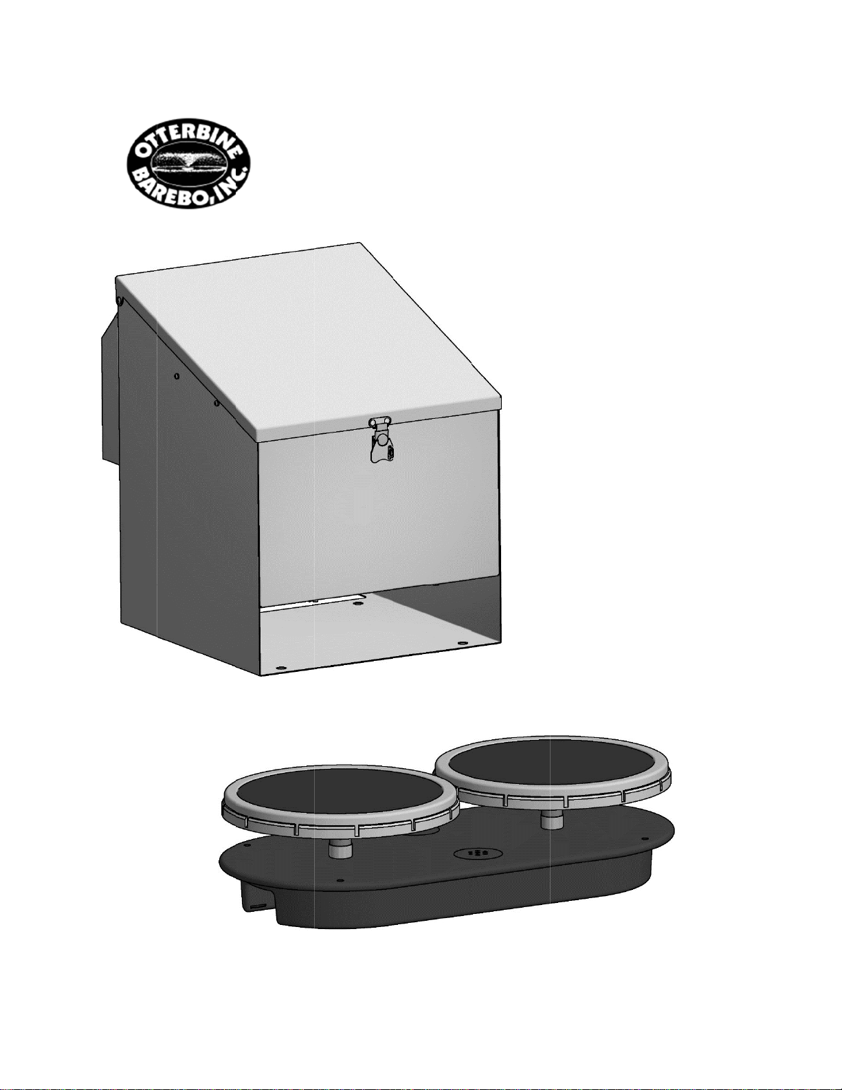
Otterbine®Air-Flo 3
WARRANTY: Barebo, Inc. 3840 Main Road East, Emmaus Pennsylvania 18049, U.S.A. hereby
warrants subject to the conditions here in below set forth, that should the OTTERBINE AirFlo 3
prove defective by reason of improper workmanship or materials at any time during the
warranty period the Purchaser at retail will be guaranteed that BAREBO will repair or replace
the said OTTERBINE AirFlo 3 as may be necessary to restore it to satisfactory operating
condition, without any charge for materials or labor necessarily incident to such repair or
replacement, provided that:
a) The enclosed Warranty Registration Card should be mailed to BAREBO within fifteen (15)
days of the original receipt by the Purchaser at retail in order to avoid delays:
b) The OTTERBINE AirFlo 3 must be delivered or shipped, prepaid, in its original container
or a container offering an equal degree of protection, to BAREBO or a facility authorized by
BAREBO to render the said repair or replacement services or, if purchased from an
authorized OTTERBINE dealer, to such dealer;
c) The OTTERBINE Air Flo must not have been altered, repaired or serviced by anyone other
than BAREBO, a service facility authorized by BAREBO to render such service, or by an
authorized BAREBO dealer, and the serial number of the OTTERBINE AirFlo 3 must not
have been removed or altered: and
d) The OTTERBINE AirFlo 3 must not have been subjected to lightning strikes and other Acts
of God, vandalism, freezing-in, accident, misuse or abuse, and must have been installed in
conformance with applicable electrical codes (including proper electrical protection), and
also installed, operated and maintained in accordance with guidelines in the Owner’s
Manual shipped with the OTTERBINE AirFlo 3.
No implied warranties of any kind are made by BAREBO in connection with this OTTERBINE
AirFlo 3, and no other warranties, whether expressed or implied, including implied warranties of
merchantability and fitness for a particular purpose, shall apply to this OTTERBINE AirFlo 3.
Should this OTTERBINE AirFlo 3 prove defective in workmanship or material, the retail
Purchaser’s sole remedy shall be repair or replacement as is hereinabove expressly provided
and, under no circumstances, shall BAREBO be liable for any loss, damage or injury, direct or
consequential, arising out of the use of, or inability to use, the OTTERBINE AirFlo 3, including
but not limited to retail Purchaser’s cost, loss of profits, goodwill, damages due to loss of
product or interruption of service, or personal injuries to Purchaser or any person.

GAST COMPRESSOR WARRANTY INFORMATION
86R & 87R Series Rocking Piston Oil-less Pump
To process any WARRANTY related activity on the AirFlo 3 Product
Contact the nearest Otterbine Service Center or the Otterbine factory directly
Visit www.otterbine.com or
Phone 1-800-237-8837 or 1-610-965-6018

Water Works With Otterbine!
Otterbine/Barebo, Inc.
3840 Main Rd. East
Emmaus, PA. 18049
U.S.A.
TOLL FREE: 1-800-AER8TER (237-8837)
PHONE: 610-965-6018
FAX: 610-965-6050
www.otterbine.com
Table of contents
Popular Lawn And Garden Equipment manuals by other brands

Yardmaster
Yardmaster 66 GEYZ Assembly instructions

Shindaiwa
Shindaiwa PowerBroom PB2500 Operator's manual

juwel
juwel PROFILINE 20590 Assembly instructions

Makita
Makita EE400MP Original instruction manual

Unigreen
Unigreen Trolleys and Barrows Operating and maintenance manual

Gardena
Gardena 4066 Operator's manual