OutBack Power FXR Series User manual
Quick Start Guide
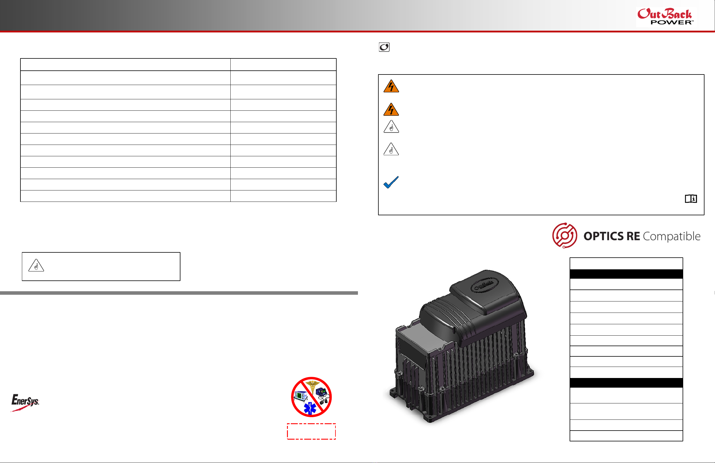
Specifications
FXR™ and VFXR™ (A) Series Inverter/Charger
900-0213-01-00 REV B
Do not copy or distribute without permission.
This Quick Start Guide is printed in unbound format. The pages can be read in any order, or shown alongside one another.
WARNING: Fire/Explosion Hazard
Do not place combustible or flammable materials within 12 feet (3.7 m) of the equipment. This unit employs mechanical relays and is not
ignition-protected. Fumes or spills from flammable materials could be ignited by sparks.
WARNING: Personal Injury
Use safe lifting techniques and standard safety equipment when working with this equipment.
IMPORTANT:
Clearance and access requirements may vary by location. Maintaining a 36” (91.4 cm) clear space in front of the system for access is
recommended. Consult local electric code to confirm clearance and access requirements for the specific location.
IMPORTANT:
These instructions are for use by qualified personnel who meet all local and governmental code requirements for licensing and training
for the installation of electrical power systems with AC and DC voltage up to 600 volts. This product is only serviceable by qualified
personnel. All system wiring must comply with national and local codes and regulations.
This product is designed and tested for stationary applications only. It is not listed or warranted for mobile use.
NOTE:
This document is for installation of a single inverter. For stacking of multiple inverters, product specifications, functions, applications,
and programming instructions, see the FXR and VFXR product literature.
This document assumes the use of the MATE3s system display. For menu navigation, see the system display product literature.
This document contains hyperlinks and QR codes leading to the product literature at www.outbackpower.com.
FXR (A Series)
Sealed Inverter
with Turbo Fan
Inverter/Charger
AC Enclosure (with Bypass Assembly)
DC Enclosure (with Inverter Disconnect)
System Display and Controller (MATE3s™)
PV Charge Controller
Communications Manager
Main Electrical Panel and
Distribution Subpanel (Load Panel)
Battery Bank
Battery Monitor
Other Components
FLEXpower™ System Products
Major System Components
Photovoltaic (PV) Array and Combiner
AC Source Utility Grid, or
AC Generator
Remote Temperature Sensor (RTS)
Surge Protector
Specification Value
Rated Temperature Range (meets component specifications; however, please note
that the inverter output wattage is derated above 25°C)
Operational Temperature Range (functions, but not rated for operation; does not
necessarily meet all component specifications)
Storage Temperature Range
IP (Ingress Protection) Rating of Enclosure
Environmental Category
Wet Locations Classification
Relative Humidity Rating
Pollution Degree Classification
Maximum Altitude Rating
–4°F to 122°F (–20°C to 50°C)
–40°F to 140°F (–40°C to 60°C)
–40°F to 140°F (–40°C to 60°C)
IP20
Indoor, Unconditioned
Wet locations: No
93%
PD 2
6561’ (2000 m)
All FXR inverters can deliver their full rated wattage at temperatures up to 25°C (77°F). The FXR
maximum wattage is rated less in higher temperatures. Above 25°C, each inverter model is derated by
a factor of 1% of that model’s rated wattage for every increase of 1°C. This derating applies to all
power conversion functions (inverting, charging, selling, offsetting, etc.)
Overvoltage Category (AC Input) 3
Overvoltage Category (DC Input) 1
Environmental Specifications
IMPORTANT:
This inverter is intended for indoor use only. Failure to
adequately protect the inverter will void the warranty.
IMPORTANT:
Not intended for use with
life support equipment.
Warranty
The warranty for this product can be downloaded from
https://www.outbackpower.com/resources/warranty/procedures
A copy is available by sending a self-addressed envelope to the address
noted to the left.
World Headquarters
2366 Bernville Road
Reading, PA 19605 USA
+1 610-208-1991 / +1 800-538-3627
EnerSys EMEA
EH Europe GmbH
Baarerstrasse 18
6300 Zug Switzerland
EnerSys Asia
152 Beach Road
Gateway East Building #11-08
Singapore 189721 / +65 6508-1780
For more information visit www.enersys.com ©2017 EnerSys. All Rights Reserved. Trademarks and logos are the property
of EnerSys and its affiliates unless otherwise noted. Subject to revisions without prior notice. E.&O.E.
Contact Information
Mailing Address: 3767 Alpha Way
Bellingham, WA 98226 USA
Web Site: www.outbackpower.com
Date and Revision
September 2022, Revision B

1
Installation
Requirements
oThe FXR and VFXR inverter/chargers are intended for
indoor installation only.
oEnsure the mounting surface is strong enough to
handle 3 times the total weight of all the components.
oThe inverter has four 0.313" (8 mm) mounting holes
( ), one in each corner. Use fasteners in all corners.
oDue to the variance in other mounting methods, OutBack
Power only endorses the use of FLEXware mounting
products. Use M6 × 20 mm machine screws, one per
corner, to attach the inverter to the mounting plate.
Follow the instructions with each mounting system.
oMount and secure each component before attaching any
wiring.
oWhen the inverter is used with other metal chassis, make
sure that all chassis are grounded. Use either metal-to-
metal contact or separate ground wires as appropriate.
oFor more information, see the FXR Installation Manual.
See QR code above.
Tools Required
oWrench and socket sets; should include
Torque and ratchet wrenches
oWire cutters/strippers
oInsulated screwdriver set (flat and Phillips);
should include
Miniature flat screwdriver for AUX connections
oLong-nose pliers
oHigh-resolution voltmeter
900-0213-01-00 REV B
Do not copy or distribute without permission.
If it becomes necessary to
remove the Turbo Fan:
1. Remove the screws at the four
corners of the Turbo Fan.
2. Remove the compartment cover.
3. Unscrew the AUX+ and AUX–
terminal screws.
4. Remove the wires.
5. Remove the Turbo Fan.
IMPORTANT:
Use correct fasteners to secure the inverter to the
mounting surface. OutBack cannot be responsible for
damage to the product if it is attached with
inadequate fasteners.
IMPORTANT:
While sealed FXR models are more tolerant of incidental
dust and moisture than VFX models, none of these products
are intended for installation outdoors. Failure to adequately
protect the inverter from weather will void the warranty.
DC Cover or Turbo Fan Attachment
FXR inverters are equipped with either the DC
Cover or the Turbo Fan. To attach either cover,
put the cover in place and insert a screw at each
corner using a Phillips screwdriver. Make
certain the red and black battery terminals are
installed before attaching the cover.
As part of attaching the Turbo Fan, follow the
wiring instructions below.
Install the wires in the AC Wiring Compartment to make
the Turbo Fan operational. The AUX+ and AUX–
terminals receive the red (+) and black (–) wires.
Tighten with a Phillips screwdriver.
To safely run the wires into the AC compartment, pass
the wires through the notch in the compartment cover.
Notch Edge of Cover
Compartment
If necessary, the green terminal block can be
unplugged by pulling it gently away from the AC board.
A
A A
A A
7.5"
(19.0 cm)
15.5"
(39.4 cm)
Make certain the AUX programming is
correct for proper fan operation.
14.0"
(35.6 cm)
12.0"
(31.8 cm)
12.0"
(31.8 cm)
12.0"
(31.8 cm)
Materials in Box
oInverter
oQuick Start Guide
(this document)
oBattery terminal
covers, red/black
o“WARNING ELECTRICAL SHOCK” sticker
oAC plate
oDC Cover (DCC) or Turbo Fan
oRemote Temp. Sensor (RTS)
oSilicone grease packet
Height with DCC
Height with Turbo Fan
1

IMPORTANT
This product requires batteries for operation.
The required nominal voltage is either 12, 24, or
48 Vdc, depending on model.
The default inverter/charger settings assume a
deep-cycle stationary lead-acid battery, such as
OutBack Power’s EnergyCell RE or NC series
batteries. Ensure the settings are appropriate
for the specific batteries used in the system.
Protection for the battery circuit external
to this product must be provided by the installer.
Protection for the AC circuit external to this
product must be provided by the installer.
For more information, see the FXR Installation
Manual.
Wiring Data
Ground Lug
1
AC Neutral
Terminals
2
3
4
Battery Positive Stud
Battery Negative Stud
5
AC Hot Out Terminal
6Ground Terminals
Inverter On/Off Jumper
7
8
AC Hot In Terminal
9
10
Inverter On/Off Terminals
Auxiliary Terminals
11
12
13
14
Temperature Sensor Port
Communication Port
Battery LED Indicators
Status LED Indicators
900-0213-01-00 REV B
Do not copy or distribute without permission.
DC Wiring Notes
oBattery cables should be no longer than 10 feet (3 m) each to minimize voltage loss and other possible effects.
oTurn off DC circuit breakers before proceeding.
oTie, tape, or twist cables together to reduce self-inductance. Run positive and negative cables through the same
knockouts and conduit.
oEach inverter battery terminal is a threaded stud which accepts a ring terminal lug. Use crimped and sealed copper ring
lugs with 5/16 inch (0.79 cm) holes, or use compression lugs.
oInstall overcurrent devices according to applicable codes.
oThe DC terminals must be installed in an enclosure to meet the requirements of some local or national codes.
AC Wiring Notes
oRecommended conductor size is #6 AWG (16 mm2) or 0.021 in2.
oInverter output varies with model. Size the loads accordingly.
oThe transfer relay is rated 60 Aac; AC input and output may need to be protected with branch-rated circuit breakers of
maximum 60 Aac size to meet applicable code requirements.
oThe neutral terminals are common. Typically only one is used.
oOnly one AC source can be wired at a time. Use an external selector switch if more than one source is available.
Generator Notes
A generator should be sized to provide enough power for maximum loads and charging at the same time.
Minimum generator size is recommended to be twice the power of the inverter(s) due to overload and/or
balancing issues.
1
2
3
4
5
5
6
7
8910
11
12
13 14
6
Inverter
(Wattage/Voltage)
Nominal
DC Amps
(Derated 125%)
Conductor Size
(Minimum)
Breaker
Size
(Minimum)
FXR2012A
VFXR2812A
FXR2524A
VFXR3524A
FXR3048A
VFXR3648A
Terminal Location
Inverter DC Terminals
Battery Terminals
200 4/0 AWG (120 mm2) or 0.186 in2250 Adc
280 4/0 AWG (120 mm2) or 0.186 in2250 Adc
125 2/0 AWG (70 mm2) or 0.109 in2175 Adc
175 4/0 AWG (120 mm2) or 0.186 in2250 Adc
75 1/0 AWG (70 mm2) or 0.109 in2125 Adc
90 1/0 AWG (70 mm2) or 0.109 in2125 Adc
Torque Requirements
60 in-lb (6.9 Nm)
See battery manufacturer’s recommendations
CAUTION:
Equipment Damage
When connecting battery cables to the
inverter, observe the proper polarity.
Incorrect connection can damage or
destroy the equipment and void the
product warranty.
!
M8 x 1.25 Stud
Insulator
Mounting
Surface
Battery
Terminal Post
Lock Washer
Battery Cable Connections
13 mm Nut
Battery
Cable
Lug
CAUTION: Fire Hazard
Do not stack battery terminal hardware
in any other order than shown here.
Stacking terminal hardware in any other
order can overheat the terminals.
Other devices may be installed on
the same inverter studs above the
hardware shown here.
!
Grounding Notes
oThis product meets the IEC requirements of Protection Class I.
oThis product must be connected to a permanent wiring system that is grounded according to the IEC 60364 TN standard.
oThe input and output circuits are isolated from ground. The installer is responsible for system grounding according to all
applicable codes.
oThe central AC ground terminals are common. Typically only one is used.
WARNING: Shock Hazard
For safety, the neutral and ground conductors should be mechanically bonded. OutBack Power
does not bond these conductors within the inverter. Some codes require the bond to be made at the
main panel only. Make sure that no more than one bond is present in the AC system at any time.
For all installations, the negative battery conductor should be bonded to the grounding system at
only one point. If the OutBack Power GFDI is present, it can provide the bond.
Terminal Location Minimum Conductor Size Torque Requirements
Central AC Terminals
DC Box Lug
#10 AWG (0.009 in²) or 6 mm² 25 in-lb (2.8 Nm)
#6 AWG* (0.025 in²) or 16 mm² 45 in-lb (5.1 Nm)
*Accepts up to 1/0 AWG (70 mm² or 0.109 in²) wire. The DC Cover or Turbo Fan must be removed before making the ground connection.
Flat Washer
1
1

CAUTION: Fire Hazard
Before energizing, confirm that all hardware
is installed as shown on the Installation page.
Stacking battery terminal hardware in any
other order can overheat the terminals.
!
900-0213-01-00 REV B
Do not copy or distribute without permission.
Energize/Startup
Procedures
De-energize/Shutdown
Procedures
WARNING: Lethal Voltage
Review the system configuration to identify all possible sources of
energy. Ensure ALL sources of power are disconnected before
performing any installation or maintenance on this equipment.
Confirm that the terminals are de-energized using a validated
voltmeter (rated for a minimum 1000 Vac and 1000 Vdc) to verify
the de-energized condition.
WARNING: Lethal Voltage
The numbered steps will remove power from the inverter and
charge controller. However, sources of energy may still be
present inside the wiring boxes and other locations. To ensure
absolute safety, disconnect ALL power connections at the source.
WARNING: Burn Hazard
Internal parts can become hot during operation. Do not remove
the cover during operation or touch any internal parts. Be sure to
allow them sufficient time to cool down before attempting to
perform any maintenance.
To de-energize or shut down the OutBack Power devices:
1. Open the AC circuit breakers.
2. Open the DC circuit breaker for the battery.
3. Open the PV circuit breaker, if present.
4. Open the ground-fault circuit breaker, if present.
5. Open the FLEXnet DC circuit breaker, if present.
6. Verify 0 Vdc on the DC input terminals of the inverter by placing the
voltmeter leads on and .
7. Verify 0 Vdc on the PV charge controller terminals, if present.
8. Verify less than 5 Vac on the AC output circuit terminals
and .
9. Verify less than 5 Vac on the AC input circuit terminals
and .
2
3
4
4a 4b
Pre-startup Procedures
After opening the AC and DC enclosures:
1. Double-check all wiring connections. Ensure all torque values are met.
See Wiring Data on the other side of this sheet.
2. Inspect any enclosures to ensure no tools or debris were left inside.
3. Disconnect all AC loads at the backup (or critical) load panel.
4. Disconnect the AC input to the inverter system at the source.
5. If a mechanical interlock is used, place it in the normal (non-bypass) position.
6. Using a digital voltmeter, verify 12, 24, or 48 Vdc at the battery source. Confirm the polarity.
These instructions assume the use of AC and DC wiring boxes of OutBack Power models.
To energize or start up the OutBack Power devices:
1. Close the DC circuit breaker from the battery bank to the inverter.
2. Using a digital voltmeter, verify 12, 24, or 48 Vdc on the DC input terminals by placing the
DVM leads on and . Confirm that the voltage and polarity are correct for the inverter
and charge controller models.
3. If PV is installed, verify the correct voltage and polarity at the charge controller terminals.
4. Close the ground-fault circuit breaker, if present.
5. Close the PV input circuit breakers, if present.
6. Close the circuit breaker for the FLEXnet DC, if present.
7. Using the system display, perform any necessary programming, particularly for the size of the
AC input source(s). See Sheet 3 for the Profile Wizard.
8. The factory default state for all FXR inverters is OFF. Using the system display, turn the
inverter to the ON state.
9. Using the DVM, verify the inverter AC output on the AC output circuit terminals and .
10. Without closing the inverter system’s AC input circuit breakers: Using the DVM, test the
voltage of any input AC source(s).
11. Connect the AC source. Close the inverter system’s AC input circuit breakers.
Using the DVM, verify 120 Vac on the AC input circuit terminals and .
NOTE: After a brief delay, the inverter’s transfer relay will activate unless the inverter’s
settings have been changed. Using the system display, verify the input source and the
inverter’s charging function. After verification, disconnect the AC source.
12. Replace the covers on the AC and DC enclosures.
13. Close the AC output circuit breakers. Turn on the AC disconnects at the load panel
and test the inverter’s output while operating loads.
1 2
5
4
2
1
6
5
3a 3b
12
2
1
3
6
65
4a4b
1
3
4
Functional Test Points
Battery Negative (–) Terminal
Battery Positive (+) Terminal
AC HOT IN Terminal
AC NEUTRAL IN Terminal*
AC HOT OUT Terminal
AC NEUTRAL OUT Terminal*
*Terminals 3b and 4b are electrically common.
1
2
3a
3b
4a
4b
3a 3b
4a 4b
1 2
4a4b
12
3
2
4
11
5
3a 3b
3a 3b
CAUTION: Equipment Damage
Incorrect battery polarity will damage the equipment.
!
12
NOTES:
o
o
If a system display is not present, the inverter must be
turned off or on using an external switch or the ON/OFF jumper.
See the Installation Manual for more instructions.
1
If any of these tests do not function as described, or for other
troubleshooting, see the Operator’s Manual.
2
900-0213-01-00 REV B
Do not copy or distribute without permission.
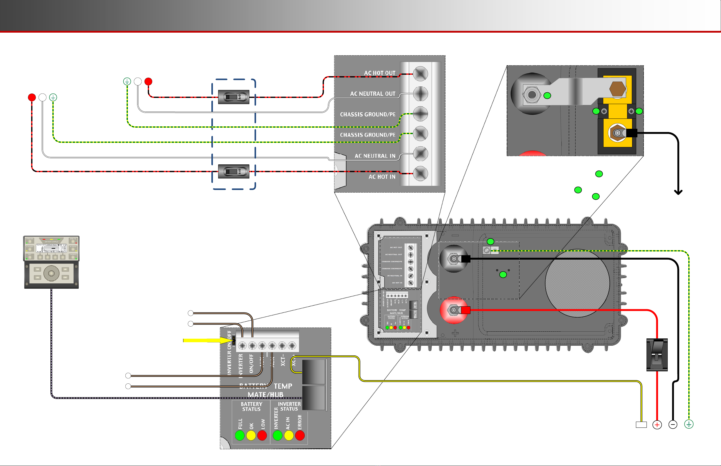
Wiring
AC
Main Panel,
Grounded,
with
AC Source
AC
Subpanel
with Loads
Battery Bank
MATE3s System
Display
On/Off
Switch
or
Rapid
Shutdown
Also
Remove
On/Off Jumper
Auxiliary Device
or Generator Start
(if used)
AC
Bypass Interlock
(if used)
With Shunt (if used)
When installing a shunt for use with the FLEXnet DC
or a similar battery monitor, remove the ground lug .
Attach the shunt using the threaded holes .
The shunt connects to the negative terminal as in .
The negative cable connects to the shunt.
1
2
2
1
2 2
3
3
FXR Inverter
L1 N
L1N
RTS

2
Setup and Programming
900-0213-01-00 REV B
Do not copy or distribute without permission.
!
Inverter Status LED Indicators
Green
Yellow
Red
Inverter on (solid) or standing by (flash)
AC source in use (solid) or standing by (flash)
Inverter error or warning (see manual)
Green
Yellow
Red
12.5 Vdc or higher
11.5 to 12.4 Vdc
11.4 Vdc or lower
Color
Battery Status LED Indicators
25.0 Vdc or higher
23.0 to 24.8 Vdc
22.8 Vdc or lower
50.0 Vdc or higher
46.0 to 49.6 Vdc
45.6 Vdc or lower
12 V Inverter 24 V Inverter 48 V Inverter
Monitoring
A
B
Profile Wizard
In the MATE3s system display, the Profile Wizard allows quick setup of parameters that apply to all systems. The Profile Wizard is
reached from the Main Menu as shown in
B
.
The Profile Wizard is useful for rapid setup of multiple parameters including date, time, battery charging, AC source size and limits, and
System Type. It can also configure functions such as High Battery Transfer and Grid Use times. Note that these two functions are not
available if the System Type is set to Off Grid.
NOTE: The Wizard does not configure the entire system. It does not select AC input modes for the FXR inverter, parameters for
automatic generators, or “fully charged” parameters if the FLEXnet DC battery monitor is in use. If settings are made in the wrong order,
the Wizard can overwrite some customized settings. See MATE3s Programming Guide for more information.
3
The firmware revision of all devices can be confirmed by navigating from the Main Menu as shown in
A
. Upgrades to the firmware
revision can be downloaded from the OutBack Power website.
4
Profile Wizard
New Profile Initialized
Back Continue
Wizard Date & Time
16:56
13 May 2022 Fri
Back Continue
Wizard System Type
System Type Grid Tied
System Voltage 48 VDC
Array Wattage 1000
Battery Type FLA Capacity 500 Ah
Back Continue
Grid Tied
Main Menu
Settings >>
Profile Wizard >>
Device Data Logs >>
Event Logs >>
Firmware Update >>
Profile Wizard
Profile Wizard
New Profile >>
Existing Profile >>
Restore Profile >>
New Profile
System Configuration
System Information >>
Save / Store Configuration >>
Firmware Version >>
Date and Time >>
LCD Display >>
Firmware Version
Firmware Versions
MATE3s 001.001.000
1:VFXR3648A 001.006.063
2:VFXR3648A 001.006.063
Main Menu
Settings >>
Profile Wizard >>
Device Data Logs >>
Event Logs >>
Firmware Update >>
Profile Wizard
Settings Menu
System >>
Inverter >>
Charge Controller >>
Battery Monitor >>
MATE3s >>
System
A
Wizard AC Configuration
AC Output Voltage 120 VAC
AC Phase Single
AC Input Breaker Size 60 A
Maximum Output Load 33 A
Back Continue
120
Wizard AC Input Limits
Grid Lower Voltage Limit 105 VAC
Grid Upper Voltage Limit 132 VAC
Gen Lower Voltage Limit 108 VAC
Gen Upper Voltage Limit 140 VAC
Back Continue
105
Wizard Generator Configuration
Generator Installed N
Generator Type AC Size 5.0 kW
Generator Start Manual
AUX Output Device Port 1
Back Continue
N
Wizard Battery Charging
Absorb Voltage 57.6 VDC Time 1.0
Float Voltage 54.4 VDC Time 1.0
Equalize Voltage 60.0 VDC Time 3.0
Re-Float Voltage 44.0 VDC
Back Continue
The FLEXnet DC (FN-DC) is a battery monitor which
measures DC current flow on one or more shunts.
It provides battery state-of-charge (SoC) information.
Exact measurements and programming are performed with
the system display. (See the system display and FLEXnet
DC literature.) The LED indicators shown below provide
approximate measurements of the battery state of charge.
FLEXnet DC Battery Monitor
oA green indicator (FULL) means the batteries have an adequate charge. It does
not always mean they are full.
oA yellow indicator (OK) means the batteries are somewhat discharged.
oA red indicator (LOW) means the batteries are greatly discharged and may require
attention. A low battery error may be accompanied by a red STATUS indicator.
The STATUS indicators show the inverter’s operating condition as shown below.
Green
Color
Red
Yellow
Yellow
Yellow ≥ 80%
≥ 70%
≥ 60%
≥ 60% off, < 60% solid, < 50% blinks
Battery State of Charge
FN-DC LED Indicators
> 90% (blinks if charge parameters are met)
After commissioning and programming the FXR system, perform a full battery charge.
Reset the FN-DC by unplugging the communications cable and then plugging it back
in. (The system must be energized at the time.) The FN-DC will reset to 100% SoC,
matching the batteries if they have been charged.
NOTE: The user must program the FN-DC with correct values for battery capacity
and charging requirements. The factory default values may not be correct. If not
programmed accurately, the FN-DC readings and LED indicators will not be accurate.
The same is true if the shunt(s) are not wired correctly. See the FLEXnet DC
Overview Guide for more information.
5
LED Indicators
The inverter has two sets of LED indicators. (See Sheet 2 for locations.)
The BATTERY indicators show the approximate battery state.
NOTE: Due to different system states, battery voltage does not always indicate an
accurate state of charge. The FN-DC is more accurate.
See the inverter Operator’s Manual for full descriptions of these LED indicators.
A
This advances the display to the Setup
Complete screen.
BIf the FLEXnet DC is installed, the
display advances to the Shunt screens.
If the FLEXnet DC is not installed, see .
C
If the System Type is Grid Tied or Backup, the
display advances to the Grid Use Schedule
screens. If the System Type is Off Grid, see .
B
C
CAUTION: Equipment Damage
These procedures should be done by a qualified installer who is trained on programming inverter power systems. Failure to set accurate
parameters for the system could potentially cause equipment damage. Damage caused by inaccurate programming is not covered by the
limited warranty for the system.
IMPORTANT
Ensure all settings are correct for the system. The Profile Wizard can be used for rapid setup. For Grid Support functions it may be
necessary to load a .GIP file. This document assumes the use of the MATE3s System Display.
Verify the firmware revision of all OutBack Power devices before use. The FXR inverter and system display may not communicate or
operate correctly unless their firmware is above a specified revision number. Radian inverters with firmware revision 001.006.061 or
higher must use the MATE3s system display.
For firmware and .GIP file installation, see the Installation Manual. For settings and functions, see the Operator’s Manual.
If FN-DC
is installed...
If
System Type
is
Grid Tied
or
Backup
...
B
C
A
Wizard Grid Use Schedule
Period 1 Enable N
Weekday Use 0:00 Drop 0:00
Weekend Use 0:00 Drop 0:00
Back Continue
N
Wizard Grid Use Schedule
Period 2 Enable N
Weekday Use 0:00 Drop 0:00
Weekend Use 0:00 Drop 0:00
Back Continue
N
Wizard High Battery Transfer
Mode Disabled
Grid Connect 48.0 VDC Delay 60 Min
Grid Disconnect 52.0 VDC Delay 60 Min
Grid Connect SOC 60% Disconnect SOC 95%
Back Continue
Disabled
Wizard Grid Use Schedule
Period 3 Enable N
Weekday Use 0:00 Drop 0:00
Weekend Use 0:00 Drop 0:00
Back Continue
N
Wizard Battery Monitor
Shunt A
Connection Inverter
Back Continue
A
Wizard Battery Monitor
Shunt A
Connection Inverter
Back Continue
B
Wizard Battery Monitor
Shunt A
Connection Inverter
Back Continue
C
Profile Wizard
Setup Complete
Exit Program Save
45
231
2
1
Other manuals for FXR Series
3
This manual suits for next models
7
Table of contents
Other OutBack Power Batteries Charger manuals


