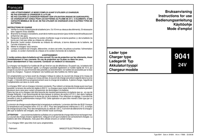
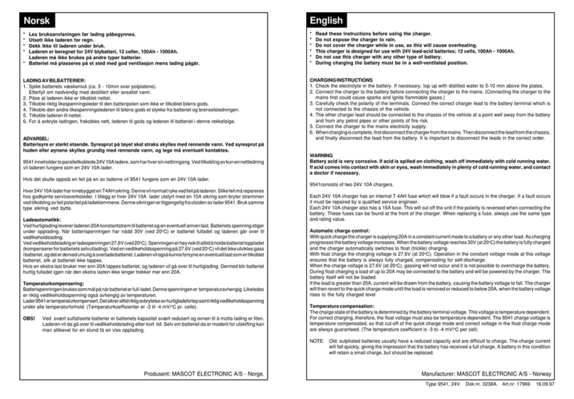
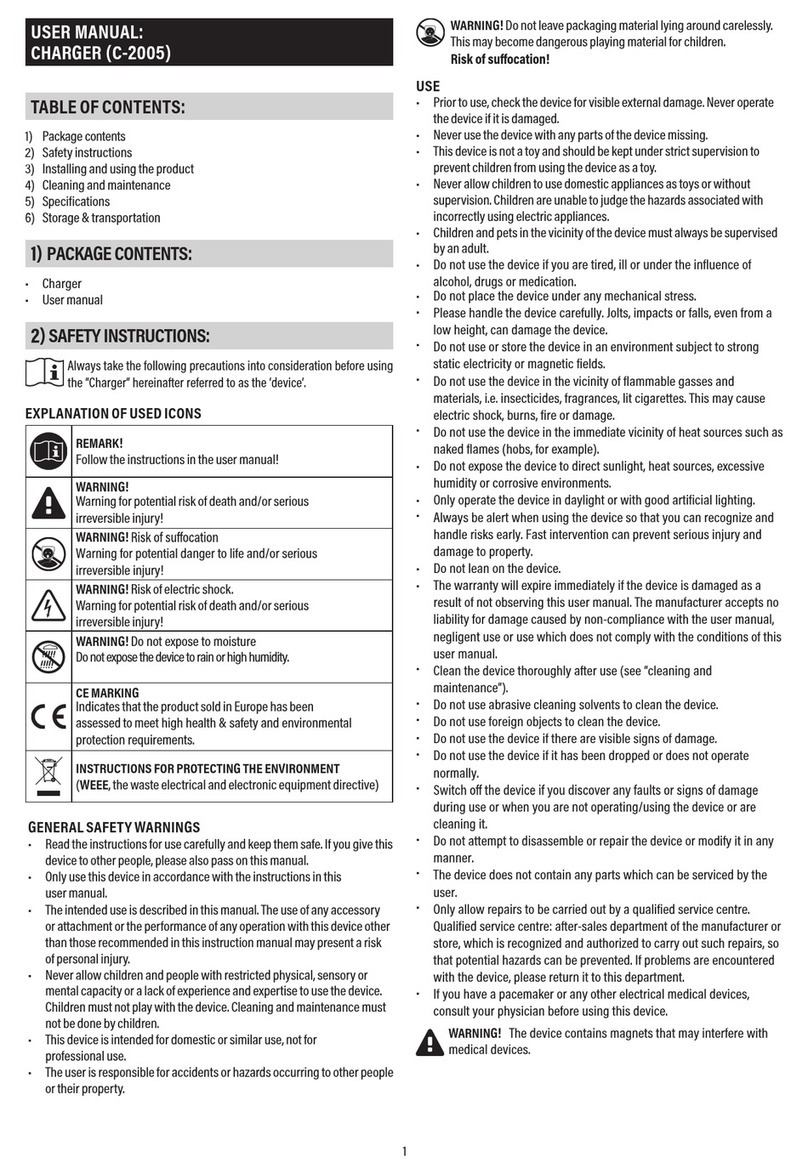
MASCOT 2115 User manual

1
Doc.no. 5120D - Part No. 205120 - 16.12.2021
Charger for
NiCd/NiMH batteries
MASCOT ELECTRONICS AS
P.O.Box 177, N-1601 Fredrikstad, NORWAY
Phone: +47 69 36 43 00 • Telefax: +47 69 36 43 01
User Manual
EN User Manual
Updates and language specific user manuals are available on
www.mascot.no/downloads/usermanuals
Bruksanvisning
Käyttöohjeet
Bedienungsanleitung
Mode d’emploi
Manual de instrucciones
Istruzioni per l’uso

2
IMPORTANT SAFETY INSTRUCTIONS!
TO REDUCE THE RISK OF FIRE AND ELECTRIC SHOCK:
READ THROUGH THESE INSTRUCTIONS PRIOR TO USING THE PRODUCT.
CAREFULLY FOLLOW THESE INSTRUCTIONS WHEN USING THE PRODUCT.
RETAIN THESE INSTRUCTIONS FOR FUTURE REFERENCE.
CAUTION! DOUBLE POLE / NEUTRAL FUSING!
This product is designed for indoor use.
(Not applicable to products marked ”IP67”)
A version of this product marked ”IP41” may be
available. This version is protected against in-
gress of solid objects larger than 1.0 mm and the
effects of vertically falling drops of water
according to standard EN/IEC 60529.
A version of this product marked ”IP4X” or ”IP40”
may be available. This version is protected against
ingress of solid objects larger than 1.0 mm.
A version of this product marked ”IP44” may
be available. This version is protected against
ingress of solid objects larger than 1.0 mm and
the effects of water splashed against the en-
closure from any direction according to standard
EN/IEC 60529.
A version of this product, marked with a sym-
bol with two drops of water and/or ”IP67”, may
be available. This version is filled with a potting
IP41 IP44 IP67
compound and is dust-tight and protected against
the effects of temporary immersion in water acco-
rding to standard EN/IEC 60529, but must not be
immersed in water for longer periods of time.
Products marked with the “double square symbol”
are double insulated (Insulation Class II). Products
without this mark are Class I (relies on safety earth
for protection).
WARNING: To avoid risk of electric shock,
Class I products must only be connected to a sup-
ply mains with protective earth.
At the end of their service life electric and ele-
ctronic equipment and their accessories shall
not be discarded with the municipal waste but be
disposed of using separate collection, treatment,
recovery/recycling and environmentally sound
disposal. This also applies to any potentially bio
hazardous parts and accessories. If in doubt, con-
tact your local authorities to determine the proper
method.
Technical specifications for your product: see
tables, the marking on the product or
www.mascot.no
IP4X
ENEN

3
Cautions to observe prior to use
•The intended use for this product is to charge
a battery or a battery powered electrical
accessory (NiCd/NiMH, Lead-Acid, Lithium-
Ion or LiFePO4batteries) or to be used as a
Power Supply to power an electrical accessory.
Please see the marking on the product you
have to verify the type of product you have and
read the applicable instructions and technical
specifications included with this manual.
• This product may be used by unskilled opera-
tors, under the condition that these instructions
are followed.
• Unskilled operators may contact the supplier
or manufacturer for assistance, if needed, in
setting up, using or maintaining this product
and to report unexpected operation or events.
• This appliance can be used by children aged
from 8 years and above and persons with
reduced physical, sensory or mental capabilities
or lack of experience and knowledge if they
have been given supervision or instruction
concerning use of the appliance in a safe way
and understand the hazards involved. Do not
allow small children to handle this product while
unattended as cables may represent a risk for
strangulation and small parts may represent a
risk for inhalation or swallowing.
• Do not allow animals to come into contact
with this product. Some animals are known to
cause damage to cables etc which may be a
potential for risk of electric shock and excessive
temperatures. Also, cables and small parts may
represent a strangulation risk for the animal.
• If the product is equipped with a mains cord,
please check that the cord is not damaged. If
the cord is damaged, the product must not be
used until the cord is replaced. Replacement
should be carried out by qualified personnel.
• The mains socket outlet used should always
be easily accessible to facilitate immediate
removal of the products mains supply should
an operational error occur during use. If the
product has a detachable mains cord the
appliance coupler may be used as a disconnect
device.
• The product is “switched on” by inserting the
mains plug into the mains socket and “switched
off” by disconnecting the mains plug from the
mains socket.
• The product may be connected to an IT type
mains supply.
• For use in U.S.A.:
- Be sure to use 125V 15A receptacle configu-
ration before plugging in.
- Use a UL817-standard compliant mains cord
(plug type NEMA 1-15, cord type SJT or SVT).
• For use outside U.S.A:
Use a mains cord compliant with the country
specific requirements.
• The time from powering this product until its full
function starts may exceed 15 seconds.
• Should an operational error or unexpected
change in the performance occur during use,
disconnect the product from the mains imme-
diately by disconnecting the mains plug from
the mains socket and contact the supplier or
manufacturer (see contact details on the front
of this document).
• When not in use please think about discon-
necting the product from the mains. This will
reduce the risk of hazards, reduce the products
environmental impact and save electricity costs.
• To avoid overheating make sure there is
sufficient room for the circulation of air around
the product when in use. Do not cover it up.
EN
4
• Even though this product complies with relevant
safety standards it should not be in contact with
human skin for long periods as some people
may get allergies or injuries from long-term
contact with moderate temperatures and/or
plastic materials.
• Prior to using this product with accessories and/
or interconnected equipment please carefully
read its respective User Manuals.
• If the product is supplied with exchangeable
output plugs, please see separate page for
assembly.
• Output cables having a modular plug ( similar to
a telephone connector) must never be connec-
ted to a telephone outlet.
• Products with a welded plastic housing or rated
IP 67 are not repairable. For such products the
supply cord cannot be replaced. If the cord is
damaged the appliance should be scrapped.
Please contact your supplier for replacement
part.
• This product contains hazardous voltages and
there are no user replaceable parts inside the
product. Never attempt to remove the cover.
WARNING: No modification of this equipment
is allowed. Any repair/service should be
carried out by qualified personnel who may get
assistance by contacting the manufacturer or
the manufacturer’s agent.
• Products specified to have automatic polarity
protection must be switched off if a battery is
connected with reverse polarity. The protection
will be automatically reset when the polarity has
been corrected.
• In chargers specified to have a replaceable fuse
as polarity protection the fuse must be replaced
if the battery has been connected with reverse
polarity. When replacing the fuse, a fuse of the
same type and rating must be used.
• If the product is specified to comply with the
standard for Medical Electrical Equipment
(standards based on IEC60601-1) it complies
with some of the requirements for medical
electrical equipment and may be used in
medical applications and hospital environments.
• The product must be kept away from sources
of heat and may not be used in the vicinity of
flammable anesthetic gases or in other environ-
ments with flammable or explosive atmosphere.
• If the product is specified to comply with the
standard for Medical Electrical Equipment
for Home Healthcare Environment (standard
IEC60601-1-11) it may be used in medical
applications used in a home healthcare
environment.
NOTE! Products relying on safety earth for
protection (Class I) may not be used in home
healthcare environment unless they are
permanently wired to the building installation:
Installation must only be carried out by
qualified service personnel, following the below
instructions:
- The protective earth conductor must be min.
0.75 mm2.
- Connect the protective earth conductor to the
external protective earthing system.
- Verify that the protective earth terminal used is
connected to the external protective earthing
system.
- Verify the integrity of the external protective
earthing system.
• This product converts the mains voltage to
a safety extra low voltage.
The output from products applying with 2MOPP
insulation ( model names followed by ”P”) may
be treated as Applied Part Type B or Type BF
according to standard EN/IEC 60601-1 and
may come in physical contact with a patient.
The housing of the product shall not be allowed
to contact the patient.
ENEN

5
• This product must be operated in an environ-
ment within temperature range +5 to +40°C,
humidity 15 - 93 % RH and atmospheric pres-
sure 70 - 106 kPa (700 - 1060 hPa). If the pro-
duct has recently been stored or transported at
conditions outsideoutside this range, please wait for 30
minutes before operating the product.
• Expected service life of this product and acces-
sories delivered with this product is three (3)
years, if operated as indicated above. However,
the guarantee times indicated in document
”TERMS OF SALES AND DELIVERY FOR MAS-
COT AS” apply (available at www.mascot.com).
• Environmental parameters during transport
and storage between uses: temperature range
-25 to +85 °C, humidity 15 - 93% RH NC and
atmospheric pressure 70 - 106 kPa (700 -
1060 hPa).
• If stored for longer periods of time the
environmental parameters should be within
the temperature range +5 to +35°C, humidity
range 10 - 75% RH NC and atmospheric
pressure 70 - 106 kPa (700 - 1060 hPa) to
maintain the products expected service life.
• Expected shelf life of this product is one (1) year,
if stored as indicated above.
• This product complies with the requirements to
electromagnetic compatibility for medical ele-
ctric equipment and for use in residential, office
or light industrial environment but all electric
products imply a potential for electromagnetic
or other interference between the product and
other devices. If such interference is suspected
please disconnect the product from the mains
and consult a qualified technician, your supplier
or the manufacturer.
• No special maintenance procedure is required
but if the product gets dusty or dirty it should be
wiped clean using a dry cloth while the product
is disconnected from the mains. No other
maintenance should be necessary.
• For products having a plastic casing, please
avoid any contact with lotions, oils, grease and
solvents as most types of plastic may be de-
graded by such chemicals. Also make sure to
position, operate and store such products away
from UV-light and direct sunlight.
• Position, operate and store this product only
under reasonable foreseeable environmental
conditions with respect to magnetic fields,
EM-fields, electrostatic discharges, pressure or
variations in pressure, acceleration etc.
• If this product is used with or mounted in a
vehicle it may only be used when the vehicle is
not in use.
• When in use, position this product so that
the label can be read – within 40 cm of the
operator.
• Turn the product off and allow it’s housing to
cool down prior to moving it to another location.
EN

6
This charger is a fast charger for NiCd/NiMH
batteries. The standard version utilizes a method
called -dV detection for charge termination when
the batteries are fully charged. This method is
based on the fact that the voltage drops over
the NiCd/NiMH cells when the batteries are fully
charged. This voltage drop is detected when the
voltage has dropped a certain percentage from
the highest value. lf this drop does not occur, the
charger has a safety timer which will terminate
charging after a given time period to avoid
overcharging the batteries.
A few cells may have a voltage drop in the first
part of the charge cycle. This is especially true
for battery cells which have been idle for a longer
period of time. Because of this, a timer is built into
the charger which prevents -dV detection the first
minutes of the charge cycle.
As the charger is programmable, it is possible that
the standard parameters, which this user manual
is based on, have been changed. See separate
user manual or contact supplier for additional
information.
Instructions for charging NiCd and NiMH batteries
Charger functionality
ENEN
• NiCd/NiMH chargers are designed for charging
NiCd and NiMH batteries only.
• Make sure you have the correct battery charger
for the battery you wish to charge. The number
of cells must correspond to the output indicated
on the charger. Never charge more battery
cells than the charger is made for.
• When charging separate battery cells, avoid
charging cells with different rest capacities at
the same time.
• Do not attempt to charge batteries that are not
rechargeable.
• Please check that the specification for your
battery allows for the maximum charge current
indicated on the charger. If in doubt, contact the
battery manufacturer for details.
• Please check that the specification for your
battery allows for the environmental conditions
present during charging.
Do not charge batteries at too high or too
low temperatures.
• Please ensure correct polarity when connecting
to the battery terminals. Reverse polarity conne-
ction may, in some chargers (see the charger’s
specification), result in a fuse rupturing, leaving
the charger useless.
• The charge cycle starts when the charger is
connected to the mains.
• If the charger is disconnected from the mains
voltage during a charge cycle the charger will
start a new charge cycle when it is reconnected
to the mains.
• When charging is complete, disconnect the
charger from the mains before removing battery
connections.
Cautions before charging NiCd
and NiMH batteries

7
• The -dV level will adapt to the number of cells
and will be approximately equally sensitive for
all number of cells.
• The safety timer will protect the batteries if a
-dV signal fails to appear during charging. It is
normal to have a safety timer that is longer than
the max. charge time.
• Some battery cells may give a voltage drop
during the initial part of the charge cycle. To
avoid interruption of the charge cycle the char-
ger has a timer that prevents -dV detection
during the first minutes of the charge cycle.
• The charger is programmed to disregard large
voltage fluctuations due to connection of exter-
nal loads etc. Such false -dV signals will be de-
tected by the software and will be disregarded.
• Top-off charge following –dV detection ensures
that all cells in a battery pack reaches full capa-
city (are balanced) prior to trickle charge.
• The charger output is protected against reverse
polarity, in most cases by an automatically re-
settable fuse.
• The charger is designed for the lowest possible
leakage current from the battery when mains is
disconnected (<1mA). Even so, it is recommen-
ded that the batteries are disconnected from the
charger when mains is not connected.
• On request the charger may be supplied with
battery temperature monitoring. A built-in tem-
perature change control (+dT/dt) secures opti-
mal charge with a built-in NTC resistor in the
battery pack.
• Other functions such as 0dV detection and
timer only charge is available upon request.
Most charge parameters may be altered using
an external programming tool. Contact Mascot
for details.
Safety features
The embedded microprocessor & charge program has numerous
features for safe battery charging
EN

8
ENEN
Start the charger by connecting the battery pack
to the charger and then connecting the charger
to the mains.
The LED (light emitting diode) will be yellow be-
fore the fast charge starts and the LED changes
to orange. When the batteries are fully charged
and the voltage drops because of the -dV signal
from the batteries, the charger will go into a top-off
charge mode before it goes over to trickle charge
mode. During top-off charge the LED will be gre-
en with a short intermittent yellow light. When the
top-off charge is completed, the charger will go
into trickle charge mode and the LED will be green.
The charge current is now reduced to a safe level,
which allows the charger to stay connected to the
battery without damaging the cells.
If the safety timer runs out before –dV is detected,
the charger will go directly to trickle charge mode
(no top-off charge) and LED will be continuously
green. lf the battery voltage is far below normal,
the charger will stop the fast charge current and
go to trickle charge mode. The LED will then indi-
cate ”error” by flickering green and orange light.
You may manually start a new charge cycle by
disconnecting mains input and connecting it again.
To charge another/next battery pack, first pack
must be disconnected for approx. 15 sec. When
LED is yellow, you may connect the next battery.
How to use the type A charger (CPM)
Start
timer Safety timer (running out if no -dV detection) Trickle charge
Battery Voltage
Initiation*
(Yellow LED)
Fast charge
(Orange LED)
Trickle charge
(Green LED)
-dV
Start timer prevents
premature –dV
Sudden –dV not caused
by fully charged battery
is disregarded
Charge current
Top-o charge
(Green LED
w. yellow ash)

9
Temperature control (optional feature)
lf the charger is used with a temperature sensor
(NTC-resistor in the battery) it is possible to
add temperature control to the battery charging
process. lf the battery temperature is too low (<
0°C) at the start of the charge cycle, the charger
will charge with low current until the temperature
level is safe. This is indicated by an intermittent
orange flash while the LED is green. Charger will
also enter low current wait mode if battery tempe-
rature is above 40 °C. The current will then remain
low until the temperature is at a level where fast
charge can start. If battery temperature exceeds
max. charge temp. (60 °C) charger enters error
mode. The LED will show ”error” by intermittently
flashing orange and green. By using the tempe-
rature increase control (+dT/dt), the charger will
switch to top-off charge and later to trickle charge
the same way as charging with -dV control.
NOTE. The charger may be programmed for other temperature parameters. See a separate user manual
or contact supplier for additional information.
Zero dV feature (optional feature)
lf zero dV has been activated, the charger will stop the fast charge when the voltage has not increased
the last 5 minutes. This feature may be the only sensor, or it may be used in combination with -dV and/
or +dT/dt
EN
LED indications
LED MODE
YELLOW Battery not connected
YELLOW Battery initialisation and analysis
ORANGE Fast charge
GREEN with intermittent
YELLOW flash
Top-Off Charge
GREEN Trickle Charge
Alternating ORANGE-GREEN ERROR
When the mains is connected the LED will be
orange for the first seconds and then turn to
yellow when the initialisation and analysis starts.
lf a battery is connected, the actual charging will
start a few seconds later when the LED changes
to orange. After the start-timer period has run out
(the first few minutes of the charge cycle when the
–dV detection is disabled), the LED will be green
for approx. 8 seconds. This is a signal for testing
and service only.When -dV has been detected, the
start of the top-off charge is indicated with a green
LED with intermittent yellow flashes. The LED is
green during trickle charge.

10
Start the charger by connecting the battery pack to
the charger and the charger to the mains.
The LED indicator will be flashing green if no bat-
tery is connected. When the battery is connected
to the output of the charger the LED will be yellow
and remain in this state until battery is fully char-
ged, and fast charge is terminated. Charger apply
low current soft start on deeply discharged bat-
teries. If voltage does not reach normal level wit-
hin a certain time, charger will enter error mode,
shown by 4 red flashes in the LED.
When –dV, +dT/dt or other EoC method is detec-
ted, the charger enters top-off mode. This is con-
trolled overcharge to make sure all cells are fully
charged. LED indication is flashing yellow.
After top-off period is ended the LED indicator will
change to green showing that battery is fully char-
ged. The charge current is now reduced to a safe
level, which allows the charger to stay connected
to the battery without damaging the cells. Several
options for trickle charge are available.
If the safety timer run out before -dV (or +dT/dt)
is detected, the charger will go directly to trickle
charge mode (no top-off charge) and LED will be
green.
You may manually start a new charge cycle by
disconnecting mains input and connecting it again.
How to use the type B charger (CBC)
Charge current
Battery Voltage
Soft start
(Yellow)
Fast charge
(Yellow)
Trickle charge
(Green)
-dV
dV mask timer prevents
premature –dV
Sudden –dV not caused
by fully charged battery
is disregarded
Top-off charge
(Flashing yellow)
Configuration
(Off, Green or flashing green )
Battery not
connected
(flashing green )
Soft start
timer
Go to error if Vbat <
Vmin after time out
Top-off
pause timer
Top-off
on timer
Safety (or charge) timer
dV mask timer
Red line: Std. continuous trickle charge
Green line: Various options for trickle charge.
Contact Mascot for this option
ENEN

11
Temperature control (optional feature)
lf the charger is used with a temperature sensor
(NTC-resistor in the battery) it is possible to add
temperature control to the battery charging
process. lf the battery temperature is too low (<
0°C) at the start of the charge cycle, the charger
will enter no current wait mode until the tempe-
rature level is safe. This is indicated by yellow
LED with 1 red blink. Charger will also enter wait
mode if battery temperature is above 40 °C, and
this is indicated by yellow LED with 2 red blinks.
The charger will be in no current wait mode until
the temperature is at a level where the charging
can start. lf the temperature is too high for safe
charging (> 60°C), the LED will show ”error” by 5
red blinks. When using the temperature increase
control (+dT/dt), the charger will switch to top-off
charge and later to trickle charge the same way as
charging with -dV control.
NOTE. The charger may be configured for other temperature parameters
or contact supplier for additional information.
Zero dV feature (optional feature)
lf zero dV has been activated, the charger will stop the fast charge when the voltage has not increased
during specified time. You may use 0dV alone or in combination with -dV and/ or +dT/dt. This function is
normally only used in special cases.
LED indications
CHARGE INDICATIONS
Flashing green: Battery not connected
Yellow: Fast charge (or soft start)
Flashing yellow: Top-off
Green: Trickle
WAIT MODE INDICATIONS
Yellow with 1 red blink: Battery temperature is too low (<0°C)
Yellow with 2 red blinks: Battery temperature is too high (>40°C)
ERROR INDICATIONS
2 red blinks: Battery is connected to charger with wrong polarity!
3 red blinks: Charger output is shorted. Check output cable connection!
4 red blinks: Battery voltage is low. Check battery status or voltage. (ss timer)
5 red blinks: Warm error. Temperature >60°C
6 red blinks: NTC missing or short (if mandatory)
LED off: Battery voltage is too high. Check battery voltage.
EN

12
ENEN
How to connect exchangeable AC-plugs
The following exchangeable AC plugs are available:
”EURO” 250V 2.5A (EN50075/IEC83 C5 II)
”US” 125V 2.5A (NEMA 1-15 / CSA-C22.2 No.42)
”UK” 250V 13A (BS 1363)
”AUS” 250V 10A (AS/NZS 3112)
Mains Cord Set is available on request if you wish your product to be ”DeskTop”
How to connect exchangeable DC-output plugs
1. To connect for desired polarity, both plug
ends are clearly marked.
2. When connected, the female plug is also
marked on each side to identify plug
polarity.
3. Shows the center polarity of the plug.
3 1 2
3 12
Mounting and use for bracket Mascot, part no. 205800
Wall mount: Fix the bracket to the wall using screws suitable for the wall material and:
head diameter: 8 - 9.5 mm, head height: max. 3 mm,
thread diameter: 4 - 5.5 mm, thread length: min. 16 mm.
Use one screw for each of the oval openings in the bracket, total four screws.
Place the Power Supply / Charger centred on the bracket so that the slot in the bottom housing is in line
with the tabs on the bracket.
Push down on the handle marked ”Push” while pushing the product against the wall. Release and the
product locks to the wall mount.
Release the product from the wall mount by pushing down on the handle marked ”Push” while pulling
the product from the wall.
If not fixed to a wall the bracket may be used as a handle, following the same procedure.

13
Electromagnetic Compatibility
In order to regulate the requirements for EMC (electromagnetic compatibility) with the aim of preventing
unsafe product situations, the EMC EN60601-1-2 standard has been implemented. This standard defines
the levels of immunity to electromagnetic interference as well as maximum levels of electromagnetic
emissions for medical devices. Medical devices manufactured by Mascot have been tested and conform
with the requirements of IEC/EN 60601-1-2, 3rd & 4th edition, nevertheless, special precautions may
need to be observed:
The Mascot products are suitable for use in Domestic, Residential, Office and Hospital environments,
except in special locations where EM Disturbances are known to be high, such as near High Frequency
Surgical Equipment or Magnetic Resonance Imaging systems.
When used according to its specification the User can expect the product to fulfil its essential performance,
being powering Medical Electrical Devices or charging batteries for Medical Electrical Devices.
WARNING: Use of this equipment adjacent to or stacked with other equipment should be avoi-
ded because it may result in improper operation. If such use is necessary, this equipment and
the other equipment should be observed to verify that they are operating normally.
WARNING: Use of accessories, transducers and cables other than provided by the manufactu-
rer could result in increased electromagnetic emissions or decreased electromagnetic im-
munity of this equipment and result in improper operation.
WARNING: Portable RF communications equipment should be used no closer than 30 cm (12
inches) to any part of the power supply or battery charger, including cables. Otherwise, degra-
dation of the performance of this equipment could result.
GUIDANCE AND MANUFACTURER’S DECLARATION
The Masot products are intended for use in the electromagnetic environment specified below. The custo-
mer or user should ensure that it is used in such an environment.
Test / Standard Compliance level Guidance
Emission:
RF emissions,
CISPR 11 Group 1, Class B Suitable for use in all establishments, inclu-
ding domestic establishments and those
directly connected to the public low-voltage
power supply network that supplies buil-
dings used for domestic purposes.
RF emissions not likely to cause any interfe-
rence in nearby electronic equipment.
However, a separation distance of 30 cm
shall be maintained.
Harmonic emissions,
IEC 61000-3-2 -
Voltage fluctuations /
flicker emissions,
IEC 61000-3-3
-
EN

14
Test / Standard Compliance level Guidance
Immunity:
Electrostatic discharge
(ESD),
IEC 61000-4-2
± 8 kV contact
± 15 kV air
Temporary loss of function may be expe-
rienced while the product is subject to
the phenomena.
The product is expected to recover to its
normal operation.
Electrostatic fast
transient / burst,
IEC 61000-4-4
± 2 kV for AC-power lines
± 1 kV for output lines
Surge, IEC 61000-4-5 ± 1 kV line to line
± 2 kV line to earth
(if applicable).
Voltage dips, short
interruptions and
voltage variations on
power supply lines,
IEC 61000-4-11
<5% UT (0.5 cycle)
40% UT (5 cycles)
70% UT (25 cycles)
<5% UT for 5 s
UT= AC Input Voltage
prior to test.
Power frequency
magnetic field
IEC 61000-4-8
3 A/m (50/60 Hz) Not applicable for non-magnetic field
sensitive devices.
Conducted RF,
IEC 61000-4-6
3 Vrms
150 kHz to 80 MHz Temporary loss of function may be expe-
rienced while the product is subject to
the phenomena.
The product is expected to recover to its
normal operation.
Radiated RF,
IEC 61000-4-3
3V/m for Professional
healthcare environment.
10 V/m for Home Health-
care environment.
80 MHz to 2.7 GHz
These guidelines may not apply in all situations.
Electromagnetic propagation is affected by absorption and reflection from structures, objects
and people and field strengths from fixed transmitters, such as base stations for radio (cellular/
cordless) telephones and land mobile radios, amateur radio, AM and FM radio broadcasts and TV
broadcasts cannot be predicted theoretically with accuracy.
To assess the electromagnetic environment due to fixed RF transmitters an EM site survey may be
considered. If the measured field strength in the location exceeds the applicable RF compliance
level above, the Mascot product should be observed to verify normal operation. If abnormal per-
formance is observed, additional measures may be necessary, such as re-orienting or relocating
the product.
ENEN

15
Specific technical data
2115/2116 2015 2215/2216 2415 2515 3015
Input voltage :
current :
frequency:
100 - 240 VAC
max.0.35 A
50 - 60 Hz
230 - 240 VAC
max.0.5 A
50 - 60 Hz
100 - 240 VAC
max.0.9 A
50 - 60 Hz
100 - 240 VAC
max. 1.3 A
50 - 60 Hz
10 – 30 VDC
max 4A
10-30 VDC
max 8A
Max. Output Power 16 W 40 W 35 W 67 W 32 W 67 W
Protection at input Fuse: T1.0 AH 250 V,
5 x 20 mm Fusible resistor Fuse: T1.6 AH 250 V,
5 x 20 mm
Fuse: T2.5 AH 250
V, 5 x 20 mm
5 A fuse
on input cable.
10A fuse
on input cable
Protection against ingress
of water (IEC 60529)
IP4X
(IP67 available) IP3X IP4X
(IP67 available)
IP4X
(IP67 available)
IP4X
(IP67 available)
IP4X
(IP67 available)
Insulation Class Class II Class II Class II Class II Class III,
common minus
Class III,
common minus
Dimensions (LxWxH) 90x45x32mm (2115)
103,5x46,8x38,7mm (2116) 100x63x47mm 107x67x36,5mm (2215)
117x75x44mm (2216) 135x80x44mm 107x67x36,5mm 135x80x44mm
Weight 125g / 150g 220g 250g 350g 250g 350g
Input terminals
- Non-detachable mains cord or 2-pin connector (IEC 60320/C8) for detachable mains cord set (2115, 2215, 2116, 2216 and 2415 only)
- Exchangeable AC adapters (model 2116 and 2216 only). 2015 has fixed plug-in connector.
- DC/DC chargers 2515 and 3015 has cable in and out.
Common technical data
TYPE A CHARGER
NiCd/NiMH
versions:
(cells in series):
3-6
cell
4-8
cell
5-10
cell
6-12
cell
10-20
cell
12-25
cell
15-30
cell
No-Load Voltage 12.8 V
± 0.7 V
16.5 V
± 1.0 V
21.0 V
± 1.2 V
24.7 V
± 1.5 V
41.0 V
± 2.0 V
51 V
± 2 V
55 V
± 3 V
Min. output voltage
for -ΔV detection 3.7 V 5.0 V 6.2 V 7.5 V 12.5 V 15 V 19 V
Max. output
voltage for -ΔV
detection
10.8 V 14.4 V 18.0 V 21.6 V 36.0 V 45 V 49.5 V

16
2115/2116 2015 2215/2216 2415 2515 3015
2 cell Fast charge:
Top-off charge:
Trickle charge:
1.3 A ± 100 mA
160 mA ± 30 mA
30 mA ± 15 mA
3-6 cell
Fast charge:
Top-off charge:
Trickle charge:
1.3 A ± 100 mA
160 mA ± 30 mA
30 mA ± 15 mA
3.5 A ± 250 mA
480 mA ± 100 mA
150 mA ± 50 mA
3.0 A ± 250 mA
390 mA ± 80 mA
100 mA ± 50 mA
4.5 A ± 350 mA
630 mA ± 100 mA
150 mA ± 50 mA
2.5 A ± 250 mA
390 mA ± 80 mA
100 mA ± 50 mA
4-8 cell
Fast charge:
Top-off charge:
Trickle charge:
1.0 A ± 100 mA
130 mA ± 30 mA
30 mA ± 15 mA
2.8 A ± 200 mA
400 mA ± 80 mA
150 mA ± 50 mA
2.2 A ± 150 mA
310 mA ± 80 mA
100 mA ± 50 mA
4.0 A ± 300 mA
560 mA ± 100 mA
130 mA ± 50 mA
2.2 A ± 150 mA
310 mA ± 80 mA
100 mA ± 50 mA
5-10 cell
Fast charge:
Top-off charge:
Trickle charge:
0.8 A ± 100 mA
110 mA ± 30 mA
30 mA ± 15 mA
2.2 A ± 150 mA
330 mA ± 70 mA
150 mA ± 50 mA
1.8 A ± 150 mA
270 mA ± 70 mA
100 mA ± 50 mA
3.5 A ± 300 mA
480 mA ± 70 mA
100 mA ± 50 mA
1.8 A ± 150 mA
270 mA ± 70 mA
100 mA ± 50 mA
6-12 cell
Fast charge:
Top-off charge:
Trickle charge:
0.7 A ± 100 mA
100 mA ± 30 mA
30 mA ± 15 mA
1.8 A ± 150 mA
270 mA ± 60 mA
100 mA ± 50 mA
1.5 A ± 100 mA
240 mA ± 60 mA
100 mA ± 50 mA
3.0 A ± 200 mA
420 mA ± 60 mA
100 mA ± 50 mA
1.5 A ± 100 mA
240 mA ± 60 mA
100 mA ± 50 mA
10-20 cell
Fast charge:
Top-off charge:
Trickle charge:
0.4 A ± 50 mA
65 mA ± 20 mA
25 mA ± 10 mA
1.2 A ± 150 mA
160 mA ± 50 mA
50 mA ± 25 mA
0.9 A ± 150 mA
130 mA ± 40 mA
50 mA ± 25 mA
1.8 A ± 150 mA
250 mA ± 50 mA
60 mA ± 30 mA
0.9 A ± 150 mA
130 mA ± 40 mA
50 mA ± 25 mA
12–25 cell
Fast charge:
Top-off charge:
Trickle charge:
1.5 A ± 100 mA
210 mA ± 50 mA
50 mA ± 30 mA
15–30 cell
Fast charge:
Top-off charge:
Trickle charge:
1.3 A ± 100 mA
170 mA ± 50 mA
50 mA ± 30 mA
40 cell
Fast charge:
Top-off charge:
Trickle charge:
1.0 A ± 100 mA
150 mA ± 40 mA
60 mA ± 25 mA
1.0 A ± 100 mA
150 mA ± 40 mA
60 mA ± 25 mA
* For custom versions see marking on product
For import to the U.S.A.: see the U.S. DOE Compliance Certification Database for maximum battery capacity allowed
Fast charge current/ Top-off current/ Trickle current, std. models*

17
Specific technical data
3546 3743 3540 (115VAC) 3540 (230VAC)
Input voltage :
current :
frequency:
100 - 240 VAC
max.0.7 A
50 - 60 Hz
100 - 240 VAC
max.0.5 A
50 - 60 Hz
110 - 120 VAC
max.4.3 A
50 - 60 Hz
220 - 240 VAC
max.2.4 A
50 Hz
Max. Output Power 30 W 16 W 252 W 294 W
Protection at input Fuse: T1.6 AH 250 V,
5 x 20 mm
Fuse: T1.0 AH 250 V,
5 x 20 mm
Fuse: T6.3 AH 250 V,
5 x 20 mm
Fuse: T3.15 AH 250 V,
5 x 20 mm
Protection against ingress of
water (IEC 60529) IP4X IP41 IP41/IP44
Insulation Class Class II Class II Class II
Dimensions (LxWxH) 123x49.5x37mm 108.5x49x29.3mm 210x113x53mm
Weight 220g 150g With mains cable 1400g. With IEC60320 1150g
Input terminals 2-pin connector (IEC 60320/C8) for excangeable mains plug (EU,
US, UK and AUS) or detachable mains cord set
Non-detachable mains cord or 2-pin connector (IEC 60320/C8)
for detachable mains cord set (220-240VAC version only)
Common technical data
TYPE B CHARGER
NiCd/NiMH
versions:
(cells in series):
2
cell
3-6
cell
4-8
cell
5-10
cell
6-12
cell
10-20
cell
22
cell
Min. output voltage
for -ΔV detection 2.5 V 3.7 V 5.0 V 6.2 V 7.5 V 12.5 V 27.5 V
Max. output
voltage for -ΔV
detection
3.4 V 10.2 V 13.6 V 17.0 V 20.4 V 34V 37.4 V

18
3546 3743 3540(P) & 3540B(P)
115VAC
3540(P) & 3540B(P)
230VAC
2 cell Fast charge:
Top-off charge:
Trickle charge:
2,5 A ± 100 mA
300 mA ± 50 mA
100 mA ± 25 mA
1,3 A ± 100 mA
160 mA ± 30 mA
30 mA ± 15 mA
20A ± 0.4A
2.9A ± 0.4A
1A ± 0.4A
20A ± 0.4A
2.9A ± 0.4A
1A ± 0.4A
3-6 cell
Fast charge:
Top-off charge:
Trickle charge:
2,2 A ± 100 mA
310 mA± 50 mA
100 mA ± 25 mA
1,3 A ± 100 mA
160 mA ± 30 mA
30 mA ± 15 mA
20A ± 0.4A
2.9A ± 0.4A
1A ± 0.4A
20A ± 0.4A
2.9A ± 0.4A
1A ± 0.4A
4-8 cell
Fast charge:
Top-off charge:
Trickle charge:
2 A ± 100 mA
290 mA ± 50 mA
100 mA ± 25 mA
1,0 A ± 100 mA
130 mA ± 30 mA
30 mA ± 15 mA
17,5A ± 0.4A
2.65A ± 0.4A
1A ± 0.4A
20A ± 0.4A
2.9A ± 0.4A
1A ± 0.4A
5-10 cell
Fast charge:
Top-off charge:
Trickle charge:
1,6A ± 100 mA
250 mA ± 50 mA
100 mA ± 25 mA
0,8 A ± 100 mA
110 mA ± 30 mA
30 mA ± 15 mA
14A ± 0.4A
2.3A ± 0.4A
1A ± 0.4A
16,3A ± 0.4A
2.53A ± 0.4A
1A ± 0.4A
6-12 cell
Fast charge:
Top-off charge:
Trickle charge:
1,3A ± 100 mA
220 mA ± 30 mA
100 mA ± 25 mA
0,7 A ± 100 mA
100 mA ± 30 mA
30 mA ± 15 mA
11,6A ± 0.4A
2.06A ± 0.4A
1A ± 0.4A
13,6A ± 0.4A
2.26A ± 0.4A
1A ± 0.4A
10-20 cell
Fast charge:
Top-off charge:
Trickle charge:
0,8 A ± 50 mA
125 mA ± 20 mA
50 mA ± 15 mA
0,4 A ± 50 mA
65 mA ± 20 mA
25 mA ± 10 mA
7.0A ± 0.3A
1.15A ± 0.2A
0.5A ± 0.1A
8.1A ± 0.3A
1.26A ± 0.2A
0.5A ± 0.1A
20-22 cell
Fast charge:
Top-off charge:
Trickle charge:
NA NA
6.3A ± 0.3A
1.08A ± 0.2A
0.5A ± 0.1A
7.4A ± 0.3A
1.19A ± 0.2A
0.5A ± 0.1A
Fast charge current/ Top-off current/ Trickle current, std. models*
* For custom versions see marking on product
For import to the U.S.A.: see the U.S. DOE Compliance Certification Database for maximum battery capacity allowed
(P)=2MOPP version. (B)=Special open frame PCB. (All standard versions are also available as open frame units).
This manual suits for next models
10
Table of contents
Other MASCOT Batteries Charger manuals

MASCOT
MASCOT 2240P User manual

MASCOT
MASCOT C-2005 User manual

MASCOT
MASCOT LiFePO4 User manual

MASCOT
MASCOT 2240 User manual

MASCOT
MASCOT 8715 User manual

MASCOT
MASCOT 2015 User manual

MASCOT
MASCOT 2240P User manual

MASCOT
MASCOT 2240 (P) User manual

MASCOT
MASCOT 9640 12V User manual

MASCOT
MASCOT 9940 User manual
Popular Batteries Charger manuals by other brands

Renogy
Renogy REGO RBC1260DO-12B user manual

IDEAL OF SWEDEN
IDEAL OF SWEDEN QI user manual

Solar Electronics
Solar Electronics Fronius Symo Installation

Milwaukee
Milwaukee M12 RCDAB+ Original instructions

ROBBE
ROBBE C8 EQ-BID 180W Power Peak operating instructions

Blueshape
Blueshape CVS8XW operating instructions