Outdoor GreatRoom Company Intrigue INT-1 User manual

Page | 1 Intrigue 90215 REV E 6/7/2012
Intrigue
User Manual for: INT-1 , INT-20
GAS-FIRED
CAUTION
DO NOT DISCARD THIS MANUAL
Important operating and
maintenance instructions
included.
Read, understand, and
follow these instructions
for safe installation and
operation.
WARNING
WARNING
If the information in these instructions
is not followed exactly, a fire or
explosion may result causing property
damage, personal injury, or loss of life.
Do not store gasoline or other flammable vapors or
liquids in the vicinity of this or any other appliance.
What to do if you smell gas:
Do not try to light any appliance
Do not touch any electrical switch. Do not
use any phone in your building.
Immediately call your gas supplier from a
neighbor’s phone. Follow the gas supplier’s
Instructions.
If you cannot reach your gas supplier, call the
fire department.
Installation and service must be performed by a
qualified installer, service agency, or the gas
supplier.
HOT! DO NOT TOUCH.
SEVERE BURNS MAY RESULT.
CLOTHING IGNITION MAY RESULT.
Glass and other surfaces are hot
during operation and cool-down.
Keep children away.
CAREFULLY SUPERVISE children near this
appliance.
Alert children and adults to hazards of high
temperatures.
Keep clothing, furniture, draperies, and
other combustibles away.
WARNING
For outdoor use only
WARNING
It is imperative the burner be kept clean
WARNING
Improper installation, adjustment, alteration, service, or
maintenance can cause injury or property damage. Read
the installation and maintenance instructions
thoroughly before installing or servicing this equipment.

Page | 2 Intrigue 90215 REV E 6/7/2012
Read this manual before installing or operating this appliance.
Please retain this owner’s manual for future reference.
Congratulations on selecting an Outdoor GreatRoom Company decorative gas appliance.
As a new owner of an Intrigue, you’ll want to read and carefully follow all of the instructions contained in this
owner’s manual. Pay special attention to all cautions and warnings.
This owner’s manual should be retained for future reference. We suggest you keep it with other important
documents and product manuals.
This information contained in this owner’s manual, unless noted otherwise, applies to all models and gas
control systems.
Your new Intrigue will give you years of durable use and trouble-free enjoyment.
Homeowner Reference Information
Model name:______________________________ Date of purchase/installation_________
Serial Number:___________________________ Location on appliance:_________________
Dealer purchased from:____________________ Dealer Phone:________________________
Notes:______________________________________________________________________
___________________________________________________________________________
___________________________________________________________________________
We recommend that you record the following
pertinent information about your appliance
Listing Label Information/Location
The model information regarding your specific appliance can be found on the rating plate attached to your
burner via a metal chain. See the sample rating plate below for locations of specifications.
Model
Fuel Type
Orifice Size
Serial no.
XXXXXX

Page | 3 Intrigue 90215 REV E 6/7/2012
1. Listing and Code Approvals .…………….……………….…….4
A.Appliance Certification …………………………………....……4
B.BTU Specifications …………………………………..……..……..4
2. Getting Started ……………………………………………………….5
A.Design and Installation Considerations……….……….…6
B.Inspect the Appliance and Components……………..….6
C. Framing enclosures for LP Supply Systems…………....7
3. Fuel Information………………………………………………..……8
A.Fuel type……………………………………………………..………...8
B.Gas Pressure requirements……………………..…………….8
C. Gas connection….…………………………………….……………8
D.LP Gas supply information……………………………….…….9
4. Setting up the Intrigue…………………………….……….…….9
A.Burner Assembly…………………………………………….…..…9
5. Operating Your Intrigue……………………………….……….14
6. Troubleshooting………………………………………….………..16
7. Maintaining and Servicing……………………………….….…17
8. Reference Materials………………………………………..…….18
9. Warranty terms…….……………………………………………….19
Table of Contents

Page | 4 Intrigue 90215 REV E 6/7/2012
1 Listing and Code Approvals
A. Appliance Certification B. BTU Specifications
MODEL: INTRIGUE
LABORATORY: Underwriters Laboratories, Inc. (UL)
TYPE: Decorative Gas-Fired Outdoor Fireplace
STANDARD: IAS US requirements for Outdoor gas
fireplaces, Draft 4-96 and CSA requirement for
Outdoor Gas Fireplaces, CR-97-003
The Intrigue has been tested in accordance with IAS
US requirements for Outdoor Gas Fireplaces, Draft
4-96 and CSA requirement for Outdoor Gas
Fireplaces, CR-97- 003 for Canada and has been
listed by Underwriters Laboratory (UL) for installation
and operation as described in these installation and
operating instructions.
The installation must conform with local codes or, in
the absence of local codes, with the National Fuel
Gas Code ANSI Z223.1 or CAN/CGA-B149.1,
National Gas Installation Code or CAN/CGA-
B149.2, Propane Installation Code.
Model
Max InputBTUH OrificeSize
INTRIGUE-1
4500 BTU/hr #72

Page | 5 Intrigue 90215 REV E 6/7/2012
Required Tools
2 Open Ended Wrenches
To make gas connections
Leather Gloves
To protect hands while installing glass cylinder
Two (2) D Batteries and One (1) A23 battery for optional remote (not included)
Required for remote operation system.
What’s Included?
2 Getting Started
Propane hose
and regulator
(for standard
tank models)
Regulator
(for 1 lb tank models)
-OR-
Wing nut (x2)
10” Glass Cylinder
Remote (optional Accessory)
Securing Bracket
Venturi Top
Protective Sleeve
Control Module
Burner Module
Included but not pictured:
Optional cable tie
Hook and loop
fastener strip

Page | 6 Intrigue 90215 REV E 6/7/2012
This appliance is a Decorative Gas Appliance for
be used
for cooking.
Place the Intrigue on a flat and stable surface in an
outdoor location such as a patio or deck.
locate the appliance where it will get excessively
wet or submerged in water.
A. Design and Installation Considerations
When planning an appliance installation, it’s necessary to
determine the following information before installing:
Where will the appliance be installed? See section 2
Gas supply piping. See section3
Important:
In compliance with UL standards, this
appliance requires 24” of clearance to
combustibles directly above the unit.
Zero clearance on all sides of venturi top
and mounting surface is acceptable.
WARNING
The Outdoor GreatRoom Company
disclaims any responsibility for, and
the warranty will be voided by, the
following actions:
Installation and use of any damaged
components.
Modification of the burner assembly
Installation other than as instructed
by the Outdoor GreatRoom
Company.
Any such action may cause a fire hazard
WARNING
Do NOT use this appliance if any part of it has
been underwater. Have a qualified service
technician inspect the appliance and replace
any part of the control system and any gas
control which has been underwater.
WARNING
Do not burn solid fuels in this gas appliance
B. Inspect theApplianceandComponents
WARNING
Inspect appliance and components for
damage. Damaged parts may impair safe
operation.
Do NOT install damaged, incomplete,
or substitute components
Report damaged parts to your dealer.
WARNING
Asphyxiation Risk
This gas appliance is for outdoor use in a
well-ventilated space.
Carefully remove all burner components
from packaging.
Read all instructions before beginning
installation. Follow these instructions
carefully during installation to ensure
maximum safety and benefit.
WARNING
Fire Risk
Provide adequate clearance:
Around air openings.
For service access.

Page | 7 Intrigue 90215 REV E 6/7/2012
While the Intrigue was designed to hold a liquid propane tank directly beneath it, you may still prefer to
build an enclosure for larger tanks. The information in this section relates to requirements for LP
enclosures.
Ventilation
Enclosures must be ventilated by openings at the level of the cylinder valve and at floor level.
Effectiveness must be determined with the cylinder(s) in place.
One side of the enclosure must be completely open or,
For an enclosure having four sides, a top and a bottom:
-At least two ventilation openings at cylinder valve level shall be provided in the side
wall, equally sized, spaced at 180 degrees (3.14 rad), and unobstructed. Each
opening must have a total free area of not less than ½ square inch per pound (3.2 sq.
cm/kg) of stored fuel capacity and not less than a total free area of 10 square inches
(64.5 sq. cm.).
-Ventilation opening(s) must be provided at floor level and shall have a total free area
of not less than ½ square inch per pound (3.2 sq. cm/kg) of stored fuel capacity and
not less than a total free area of 10 square inches (64.5 sq. cm.) . If ventilation
openings at floor level are in a side wall, there must be at least two openings. The
bottom of the openings must be at floor level and the upper edge can’t be more
than 5 inches (127 mm) above the floor. Openings must be equally sized, spaced at
180 degrees (3.14 rad) and unobstructed.
-Every opening must have minimum dimensions to permit the entrance of a 1/8 inch
(3.2mm) rod.
Accessibility
Cylinder valves must be readily accessible for hand operation. A door on the enclosure
to gain access to cylinder valves is acceptable, provided it is non-locking and can be
opened without the use of tools.
The design of the enclosure must be such that:
-The LP supply cylinder(s) can be connected, disconnected, and the connections
inspected and tested outside the cylinder enclosure.
-Those connections which could be disturbed when installing the cylinder(s) in the
enclosure can be leak tested inside the enclosure.
-Be certain to mount or set the LP gas cylinder on a flat stable surface and retain it to
prevent it from tipping.
Minimum Clearances
If the enclosure has a floor, there must be a minimum clearance of 2 inches (50.8 mm)
from the lower surface of the floor of the enclosure to the ground.
C. Framing enclosures for LP gas supply systems

Page | 8 Intrigue 90215 REV E 6/7/2012
A. Fuel
Before making gas connections, ensure that
the appliance being installed is compatible
with the available gas type. This unit operates
on propane only.
B. Gas Pressure
Proper input pressures are required for
optimum appliance performance. Gas line
sizing requirements need to be made
following NFPA54
Pressure requirement for this
appliance: Min- 11 in w.c.
Max- 14 in. w.c.
A preset non-adjustable tank regulator is supplied
3 Fuel Information
WARNING
Fire Risk
Explosion Risk
In the event of hard pipe
Installation,
Verify inlet pressures.
High pressure may cause overfire
condition.
Low pressure may cause explosion.
Verify minimum pressures when other
household gas appliances are
operating.
Install regulator upstream of valve if line
pressure is greater than ½ psig.
WARNING
Fire Risk
Explosion Risk
Verify inlet pressures.
Gas build-up during line purge may
ignite
Purge should be performed by a
qualified technician
Ensure adequate ventilation.
Ensure there are no ignition sources
such as sparks or open flame nearby.
When hard piped, the appliance and its individual
shutoff valve must be disconnected from the gas supply
piping system during any pressures in excess of ½ psi
(3.5 kPa) .
The appliance must be isolated from the gas supply
piping system by closing its individual manual shutoff
valve during any pressure testing of the gas supply
piping system at test pressures equal to or greater than
½ psi (3.5 kPa).
C. Gas Connection
Note: Have gas supply line installed in
accordance with local building codes, if any
exist. If not, follow ANSI 223.1. Installation
should be done by a qualified installer
approved and/or licensed as required by the
locality. (In the Commonwealth of
Massachusetts installation must be performed
by a licensed plumber or gas fitter.)
A small amount of air will be in the gas
supply lines. When first lighting the
appliance, it will take a short time for
air to purge from the lines. Subsequent
lighting of unit will not require such
purging.
WARNING
CHECK FOR GAS LEAKS
Fire Risk
Explosion Risk
Asphyxiation Risk
Check all fittings and connections.
Do not use open flame to check for leaks.
After the gas line installation is complete,
all connections must be tightened and
checked for leaks with a commercially
available, non-corrosive leak-check
solution. Be sure to rinse off all leak
check solution following testing.
Fittings and connections may have loosened
during shipping and handling.

Page | 9 Intrigue 90215 REV E 6/7/2012
D. LP Gas Supply
The pressure regulator and hose assembly supplied must
be used. Replacement pressure regulators and hose
assemblies must be those specified in this manual.
The LP gas supply cylinder used with LP models must be
constructed and marked in accordance with the
specifications for LP gas cylinders of the U.S. Department
of Transportation (DOT).
Cylinders must be stored outdoors in a well-ventilated area
out of the reach of children. Disconnected cylinders must
have threaded valve plugs tightly installed and must not
be stored in a building, garage or any other enclosed
area.
Storage of this appliance indoors is permissible only if it has
been disconnected from its fuel supply
The LP gas cylinder supply system must be arranged for
vapor withdrawal.
The LP gas cylinder used must include a collar to protect the
cylinder valve.
When not in use, the LP gas must be turned off at the supply
cylinder.
The specific size and capacity of the cylinder(s) to be used:
INTRIGUE-1: 1lb screw-on cylinder
INTRIGUE-20: 20lb or larger with OPD connection
4 Setting up the Intrigue
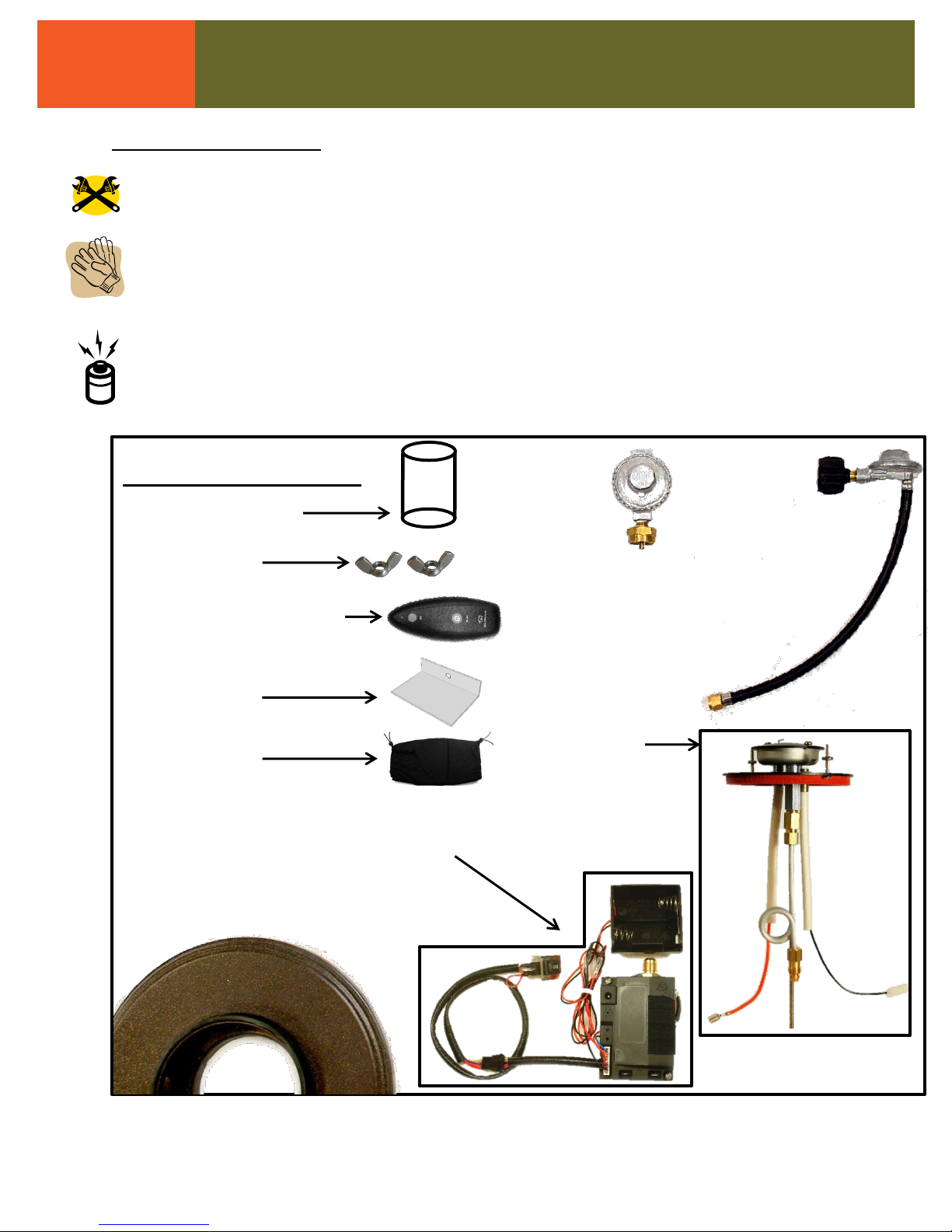
A. Burner Assembly - Before you begin-
Check for damage. Do not use damaged
components.
If there is evidence of excessive abrasion or wear,
or if the hose is damaged, the hose assembly
must be replaced prior to the appliance being put
into operation. Use only the replacement hose
assembly specified by the manufacturer.
If it is evident that the burner is damaged, the
burner must be replaced prior to the appliance
being put into operation. Use only the
replacement burner assembly specified by the
manufacturer.
Position the assembly in the desired location. You
must have easy access to the on/off switch
included with this product.
Make sure the tank valve is turned completely off
(clockwise).
Ensure the tank valve has the proper external
mating
threads (tank valve marked “USE WITH TYPE 1”).
Inspect the hose shipped with the appliance for
any
damage. Do not use if there is evidence of
damage.
A hose is included with your kit, ensure that it
is securely tightened to the fitting on the
bottom of your Intrigue before attaching hose
to tank.
Connect the regulator assembly to the tank valve.
Hand-tighten only (clockwise). Do not use a wrench
to tighten! Use of a wrench may damage the quick
closing nut and result in a hazardous condition.
Position the hose out of pathways where people
might trip over it or in areas where the hose
might be subject to accidental damage.
Before setting up the Intrigue:
Make sure the table or mounting surface chosen
contains a hole 1 1/2”-2 3/4” in diameter for proper
installation clearance and fastening.

Page | 10 Intrigue 90215 REV E 6/7/2012
Step 1:
Lower the Burner Module through
the umbrella hole in your table or
other mounting location.
1.
Step 2:
Slide the Securing Bracket up the threaded rod positioned between the ignition wires
and brass fitting at the top of the assembly facing in the direction shown below. Secure
with a wingnut. Your burner assembly is now secured to the mounting surface.
2.
Wingnut

Page | 11 Intrigue 90215 REV E 6/7/2012
3a.
Brass
fittings
Step 5:
Connect the wires hanging from the Burner
Module to the Control Module as shown at
right.
Connect the wire with the small tip to the
port labeled S
Connect the wire with the large tip to the
port labeled I
Tighten
Step 3:
Slide the Control Module up the threaded rod (through the holes shown at lower left)
Thread a wingnut onto the threaded rod to hold it in place while performing the next step.
Insert brass fitting into the hole in the top of the Control Module.
Using two wrenches, fully tighten the connection.
3c.
3b.
(Shown with battery pack removed)
I
S
5.
Attach wingnut
(snug to bottom of bracket
after completing step 3c.)

Page | 12 Intrigue 90215 REV E 6/7/2012
Step 6 :
Insert two (2) D Batteries into battery pack.
The wires connecting the battery pack to the
control module can be bundled and secured
with the included optional cable tie if desired
OR they can be left loose so that the battery
pack can be separated from the unit and
pulled out to the edge (as shown at right) for
table configurations that make it difficult to
replace batteries while they’re mounted
under the table.
Step 7:
Moving now to the top side of your table,
Remove the nuts from the threaded
rods (at right)
Set the Venturi Top on the Burner
Module lining up the threaded rods
with the holes in the underside of
the Venturi Top
Thread nuts back onto the threaded
rods and tighten to secure
7a.
Step 8:
Wearing clean, soft leather gloves and
eye protection to avoid accidental
injury while handling glass, using a wet
cotton swab, paper towel or similar,
wet the gasket to ease glass
installation.
Carefully rock glass cylinder into place
until it contacts metal base and sits flat
and level.
-OR-
6.
7b.
8a.
8b.

Page | 13 Intrigue 90215 REV E 6/7/2012
9.
Step 9:
With power switch in the OFF (Center)
position, using two wrenches, securely fasten
the supplied gas regulator or regulator and
hose assembly (shown) to the threaded
connector protruding from the bottom of the
gas valve assembly.
At this time, ensure ALL connections are
securely tightened and checked for leaks.
To install a 1lb tank, thread tank onto
brass fitting and hand tighten securely.
To install other tanks, hand tighten
plastic collar adapter onto tank valve.
Do not over-tighten.
Step 12: Concealing the valve assembly and Placing the Control switch
Your Intrigue includes a cloth bag for concealing and protecting your product’s inner workings.
To use bag, simply open one end, slide up over the valve assembly until the top of bag is above the
coiled aluminum gas line on the valve assembly. Pull drawstring to tighten. Secure bottom if not already
tightened.
The on-off switch has a built-in bracket that can be glued, screwed, or attached via hook-and-loop to
surfaces near the control module. We suggest attaching it to the underside of your table near an
outside edge to make for hassle-free operation.
Hold bead, pull
string to tighten
Turn to the next page for lighting and operation instructions
On/off
switch

Page | 14 Intrigue 90215 REV E 6/7/2012
5 Operating Your Intrigue
WARNING
Improper installation, adjustment,
alteration, service, or maintenance can
cause injury or property damage. For
assistance or additional information consult
a qualified installer, service agency, or the
gas supplier.
WARNING
Fire Risk
Burn Risk
HOT! DO NOT TOUCH.
SEVERE BURNS MAY RESULT.
CLOTHING IGNITION MAY RESULT.
Glass and other surfaces are hot during operation
and cool-down.
Children and adults should be alerted to the
hazards of high surface temperatures and should
stay away to avoid burns or clothing ignition.
Young children should be carefully supervised
when they are in the area of the appliance
Installation and repair should be done by a
qualified service person. The appliance should be
inspected before use and at least annually by a
qualified service person. More frequent cleaning
may be required as necessary. It is imperative that
control valve, burner, and air passageways in
venturi top be kept clean.
Before igniting your Intrigue for the first time:
The power switch included with your Intrigue is
labeled with three symbols. These indicate
different modes of operation. Make sure burner is
set to OFF before installing propane tank.
Remote Operation
Power/Flame OFF
Power/Flame ON (manual Ignition)
Programming a Remote:
An optional remote burner controller can be purchased for
this product.
Begin with the power switch in the Remote Operation
position.
To program your remote, locate the program button on
the Control Module (shown at right) and press it with a
paper clip or similar small object. A single chirp should be
heard.
Press the SET button on your remote and hold until two
chirps are heard from the Control Module. The remote is
now paired with your burner.
Program button
LED indicator
Speaker
SET

Page | 15 Intrigue 90215 REV E 6/7/2012
A. This appliance must be lit electronically. When
lighting, follow these instructions exactly.
B. Before lighting, smell all around the appliance area
for gas. Be sure to smell next to the base of the
appliance because some gas is heavier than air and
will settle on the floor.
WHAT TO DO IF YOU SMELL GAS:
Do not try to light any appliance.
Do not touch any electric switch, do not use any
phone nearby.
Immediately call your gas supplier from a neighbors
phone. Follow gas supplier’s instructions.
If you cannot reach your gas supplier, call the fire
department
FOR YOUR SAFETY, READ BEFORE LIGHTING
WARNING!
If you do not follow these instructions exactly, a fire or explosion may result
causing property damage, personal injury, and/or loss of life.
C. Use only your hand to turn the gas control knob
on propane tank (if equipped) , never use tools. If
the valve won’t turn by hand, don’t try to repair it,
call a qualified service technician. Force or
attempted repair may result in a fire or explosion.
D. Do not use the appliance if any part has been
underwater. Immediately call a qualified service
technician to inspect the appliance and replace any
part which has been underwater.
E. The gas pressure regulator provided with this
appliance must be used. This regulator is set for an
outlet pressure of 10.5 inches water column.
Lighting Instructions
1. STOP! Read the safety information above.
2. Open propane tank valve (if equipped)
3. Locate three-position switch and set to ON
position (I)
4. Burner should beep twice and begin sparking.
During first use, it may take longer than
usual for flame to ignite due to air being
present in gas line. This is normal.
If sparking stops before flame ignites, turn
the unit to the OFF position (O) and consult
troubleshooting section of this manual (P.15)
5. To extinguish, put switch in OFF position.
Manual Ignition
6. STOP! Read the safety information above.
7. Open propane tank valve (if equipped)
8. Locate three-position switch and set to REMOTE
position (II)
9. If using remote for the first time you will need to
program it to work with your Intrigue.
Using a toothpick or other small instrument,
depress the button on the remote receiver
(located in the hole directly adjacent to the
LED that flashes when the unit is turned on)
until a beep is heard.
Immediately press and hold the “set” button
on your remote until two beeps are heard.
This confirms remote has been programmed.
10. Burner should beep twice and begin sparking.
During first use, it may take longer than
usual for flame to ignite due to air being
present in gas line. This is normal.
If sparking stops before flame ignites, turn
the unit to the OFF position (O) and consult
troubleshooting section of this manual (P.15)
11. To extinguish, press ON/OFF button on remote.
Remote Setup and Ignition
NOTE:
This device contains an intelligent flame recognition system
which will produce a spark until the presence of a flame is
detected. Ensure that burner area and sensing/igniting
electrodes are kept clear for proper operation.

Page | 16 Intrigue 90215 REV E 6/7/2012
WARNING
Fire Risk
High Temperatures
Keep combustible household items away from
appliance.
Do NOT obstruct combustion and ventilation
air.
Do NOT place combustible items on top of or
near appliance.
Keep furniture, draperies away from
appliance.
Do NOT use gasoline, lantern fuel, kerosene,
charcoal lighter fluid, or similar liquids in this
appliance.
Combustible materials, flammable liquids, or
vapors may ignite.
6 Troubleshooting
With proper installation, operation, and maintenance, your Intrigue will provide years of trouble-free service. If you do
experience a problem, this troubleshooting guide will assist a qualified service person in the diagnosis of a problem and
the corrective action to be taken. This troubleshooting guide should only be used by a qualified service technician.
Symptom Possible Causes Corrective Actions
Igniter sparks but
will not light
Tank may be empty Replace tank with a full one
Spark may not be occurring from burner area Ensure wires are not shorted or pinched
Replace bad wires and check all connections.
Unit ignites but will
not stay lit, or spark
continues after
ignition
Sensing rod may not be near enough to flame relocate sensing rod into flame
Sensing rod may be blocked by debris Clean burner and sensing electrode
Glass may not be installed correctly Re-seat glass on gasket snugly
Burner may be wet Dry off burner and check ports for water
The unit may have low batteries replace used batteries
Burner ignites and
self-extinguishes
No spark is present
when attempting to
ignite
Batteries not installed or batteries may be dead Replace batteries
Switch wiring may be damaged or disconnected Check wiring for damage. Replace wiring if
needed

Page | 17 Intrigue 90215 REV E 6/7/2012
7 Maintaining and Servicing
Although the frequency of appliance servicing and
maintenance will depend on the use and type of
installation, a qualified service technician should
perform an appliance checkup annually.
Storage of an appliance indoors is permissible only
if the cylinder is disconnected and removed from
the appliance.
WARNING
Annual inspection by a qualified
technician is recommended.
Check:
Obstructions of combustion and
ventilation air.
Condition of burner assembly.
Burner ignition and operation.
Gas connections and fittings.
Risk of:
Fire
Delayed ignition or explosion
Exposure to combustion fumes
Odors
WARNING
Risk of injury or property damage
Before servicing:
Turn off utilities to appliance.
Ensure the appliance is completely cooled.
Inspect Maintenance Tasks
Glass
Inspect glass for cracks or chips
Carefully remove glass and clean
Venturi Disc
With glass removed, inspect venturi disc for debris
or damage.
Clean disc using a soft rag and non-abrasive cleaner
Burner Assembly
Inspect for damage or debris.
Carefully wipe down surface being careful not
to bend or break electrodes
Valve and remote
assembly
Inspect for damaged or disconnected wires
Ensure correct operation of ignition and remote system
Check for gas leaks and tighten connections

Page | 18 Intrigue 90215 REV E 6/7/2012
The Outdoor Greatroom Company
2015 Silver Bell Road, #195, Eagan, MN 55122
www.outdoorgreatrooms.com
Please contact your Outdoor Greatroom Company dealer
with any questions or concerns. For the
number of your nearest Outdoor Greatroom
dealer, please call 866.303.4028.
- NOTES -
8 Reference Materials
Part description Part Number QTY
10” Glass cylinder INTRIGUE-GLASS 1
Venturi disc INTRIGUE-VFTOP 1
Battery Pack INTRIGUE-BATT 1
Electronically controlled gas valve INTRIGUE-VALVE 1
Igniter INTRIGUE-SPARK 1
Flame sensor INTRIGUE-SENSE 1
Control Switch INTRIGUE-SWICH 1
Hose and regulator for 1lb model INTRIGUE-REG1 1
Hose and regulator for 20lb model INTRIGUE-REG20 1
Remote controller INTRIGUE-REMT 1

Page | 19 Intrigue 90215 REV E 6/7/2012
The Outdoor Greatroom Company extends the following warranty for Outdoor Greatroom
outdoor products used in the United States of America or Canada. Dealers and employees of The
Outdoor Greatroom Company have no authority to make any warranty or authorize any remedies in
addition to or inconsistent with the terms of this warranty. This warranty gives you specific legal
rights. You may also have other rights that vary from state to state.
The Outdoor Greatroom Company warrants that this Outdoor Greatroom Outdoor Product (the
“Product”) will be free from defects in material and workmanship for a period of one year from its
date of purchase. This warranty is subject to the conditions, exclusions and limitations described
below.
This warranty applies only to the original owner of the Product and is non-transferable. The Outdoor
Greatroom Company obligation under this warranty does not extend to damages resulting from (1)
assembly, operation or maintenance of the Product not in accordance with the Installation/Assembly
Instructions, Operating Instructions and the Listing Agency Identification Label furnished with the
Product; (2) installation or use which does not comply with local building codes and ordinances;
(3) shipping, improper handling, improper operation, abuse, misuse, accident or unworkmanlike
repairs; (4) use of fuels other than those specified in the Operating Instructions; (5) Installation or use
of components not supplied with the Product or any other components not expressly authorized and
approved in writing by The Outdoor Greatroom Company; and/or (6) modification of the Product not
expressly authorized and approved in writing by The Outdoor Greatroom Company. Any of the
circumstances described in the previous sentence voids this warranty. This warranty is void if the
Product or any component has been removed, repaired, or replaced before The Outdoor Greatroom
Company has been afforded a reasonable opportunity to inspect the Product.
This warranty is limited to the replacement or repair of defective components or workmanship and
The Outdoor Greatroom Company may fully discharge its obligations under this warranty by
repairing or replacing, at its discretion, the defective components. The Outdoor Greatroom
Company will provide replacement parts at no charge and will pay reasonable and necessary labor
and freight costs related to replacing or repairing defective components under this warranty. The
maximum amount recoverable under this warranty is limited to the purchase price of the Product
and, if The Outdoor Greatroom Company is unable to provide replacement or repair in an
expedient and cost-effective manner, The Outdoor Greatroom Company may discharge all
obligations under this warranty by refunding the purchase price of the Product.
EXCEPT TO THE EXTENT PROVIDED BY LAW, THE OUTDOOR GREATROOM COMPANY
MAKES NO EXPRESS WARRANTIES OTHER THAN THE WARRANTY EXPRESSED HEREIN. THE
DURATION OF ANY IMPLIED WARRANTY IS LIMITED TO THE DURATION OF THE WARRANTY
SPECIFIED ABOVE. IN NO EVENT SHALL THE OUTDOOR GREATROOM COMPANY BE LIABLE
FOR ANY INCIDENTAL OR CONSEQUENTIAL DAMAGES CAUSED BY DEFECTS IN THE
PRODUCT. Some states do not allow limitations on how long an implied warranty lasts, or do not
allow exclusion or limitation of incidental or consequential damages, so these limitations may not
apply to you.
To obtain service underthis warranty, you must:
1.Send written notice of the claimed condition to: The Outdoor Greatroom Company, 2015
Silver Bell Road, #195, Eagan, MN 55122.
2.Affirm that you are the original owner of the Product.
3.Provide The Outdoor Greatroom Company reasonable opportunity to investigate the claim,
including reasonable opportunity to inspect the Product prior to any repair or replacement work
and before the Product or any component of the Product has been removed.
The Outdoor GreatRoom Company
Outdoor Products Limited One-Year
Warranty
This manual suits for next models
1
Table of contents