5
LANX HD
®
is protected with a pin code that unlock other different features and
setup menu available only for the person in charge of the vehicles. To unlock the
setup menu with the PIN CODE see the “Calibration manual”.
The standard features available for the user are: operator selection, print load, lo-
loads Database (save loads Database), diagnostic, edit materials, edit operators,
tare button and materials selection button.
LANX HD
®
, in addition to indicating the net and gross weight loaded on the vehicle
and memorizing it automatically, also performs other secondary functions which can
be set using the Functions and OK buttons.
4.1 Operator selection
This function allows the user to select until 32 operators or loading destinations.
• Press Functions to display:
• Press OK to enter the function
• Scroll and through the functions to select the operator or the loading desti-
nations
• Press the OK button to confirm the operation.
4.2 Print loads
This function allows the user to print the weights measured during the day. The
date, time, operator/destination and material loaded during the entire workday is
printed on the ticket.
• Press Functions and button to display:
• Press OK button to print
• Example of a printed ticket:
• Press the Functions button to cancel the
operation
To display or print the daily, weekly or monthly
weights, see the “Loads Database” section and it
is necessary to enter the protective PIN CODE to
unlock the functions.
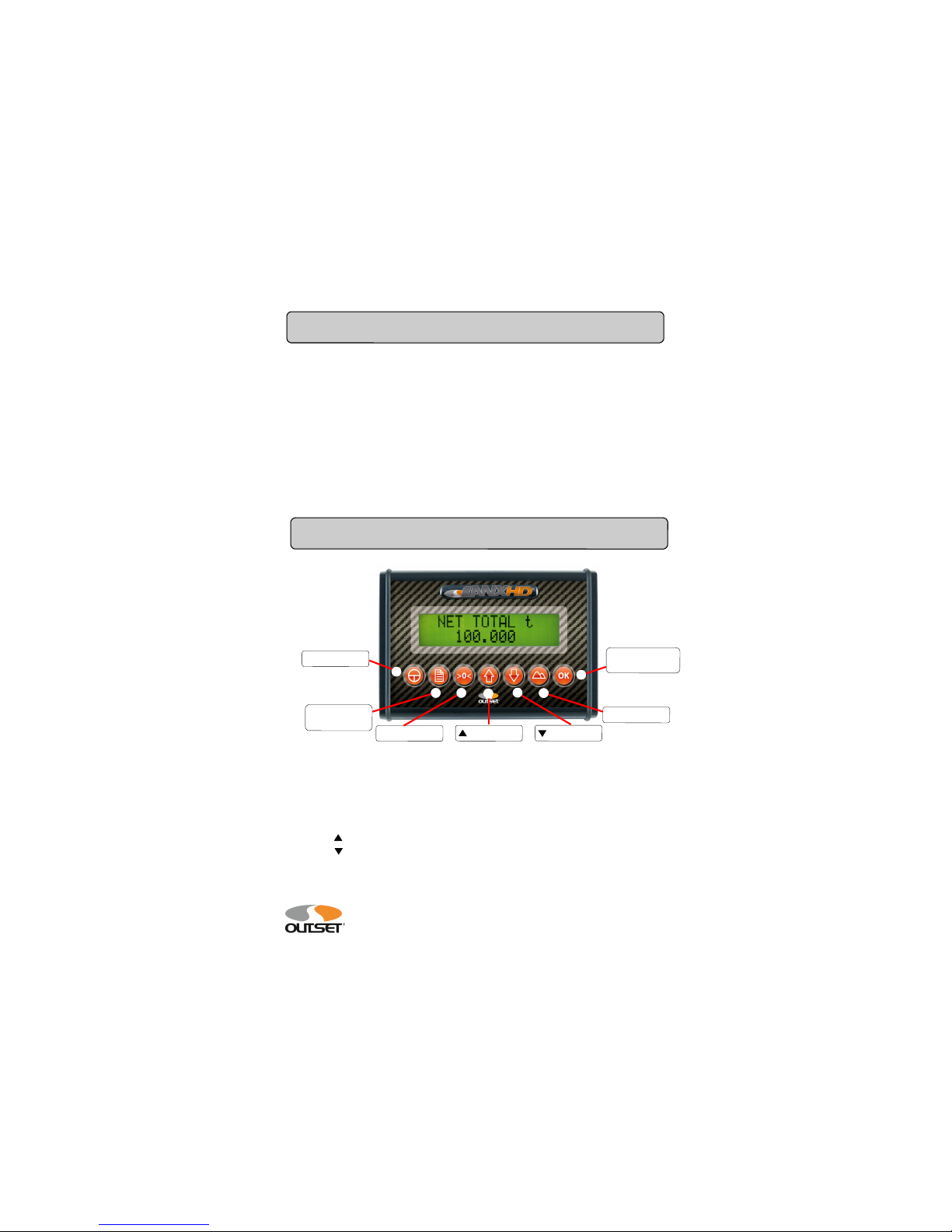
3PIN CODE
4Functions
General
GeneralGeneral
General
OPERATOR SEL.
OPERATOR SEL.OPERATOR SEL.
OPERATOR SEL.
***************************************************
LANX
....
OUTSET srl
....
31/01/2011 19.30
********************ID TRUCK*******************
***************************************************
*** MATERIAL 01 ***
*** OPERATOR/DESTINATION ***
31/01/11 08.30 kg 75100
31/01/11 09.15 kg 77200
31/01/11 10.47 kg 75150
--------------------------------------------------------
TOTAL 227450
--------------------------------------------------------
*** MATERIAL 02 ***
31/01/11 11.15 kg 75100
31/01/11 12.05 kg 77200
--------------------------------------------------------
TOTAL 152300
-------------------------------------------------------
General
GeneralGeneral
General
PRINT LOADS
PRINT LOADSPRINT LOADS
PRINT LOADS