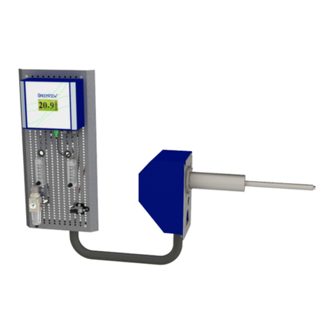
GREEN INSTRUMENTS G4100 User manual

G4100
Analyzing System Manual
Document ID number.: 01271

2

G4100 NOx/O2 Analyzing System
3
Contents
1INTRODUCTION 4
1.1 10BABOUT THIS MANUAL 4
1.2 11BINQUIRIES AND FEEDBACK 5
2SYSTEM SPECIFICATIONS 6
3SYSTEM INSTALLATION 7
3.1 CONTROLAT DELIVERY 7
3.2 WHERE TO INSTALL THE SYSTEM 7
3.3 SAFETY ASPECTS 8
3.4 EJECTOR PROBE 8
3.5 ANALYZING BOARD 12
3.5.1 Mounting Panel 12
3.5.2 Air Supply Connection 13
3.5.3 Span NOXGas Connection 14
3.5.4 Analyzer and Electrical Connections 14
4COMMISSIONING 15
4.1 INSTALLATION CHECKS OF THE SAMPLING BOARD 15
4.2 COMMISSIONING OF THE ANALYZER 15
4.3 START OF SYSTEMS 15
5OPERATION 16
5.1 CALIBRATION MODE 16
5.2 MEASUREMENT MODE 16
6ROUTINE MAINTENANCE 17
6.1 AIR FLOW SYSTEM 17
6.2 SENSOR 17
6.3 EJECTOR PROBE 18
7PARTS LIST 21
List of Figures
FIGURE 3-1: INSTALLATION LAYOUT OF THE EJECTOR PROBE 9
FIGURE 3-2: EJECTOR PROBE DIMENSIONS 10
FIGURE 6-1: EJECTOR PROBE 18

Introduction
4
1Introduction
1.1 10BAbout this Manual
This manual contains the data and instructions for the installation, operation, and mainte-
nance of the gas sampling board with the sampling probe of the G4100 NOX/O2Analyzing
System.
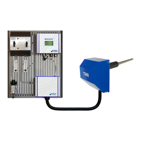
The G4100 NOX/O2Analyzing System consists of two parts:
•G41 NOX/O2Analyzer
•G4100 NOX/O2gas sampling board with the sampling probe
The instructions for installation, operation, and maintenance of the analyzers are provid-
ed in the separate manual –the G41 NOx/O2Analyzer manual (p# 01250 or 01819).
For the installation, operation, and maintenance of the G4100 NOX/O2Analyzing System,
both manuals must be read carefully in their entirety.
The manual has been made in general terms and do not take into consideration a specific
installation. As such, the instruction manual is designed for the standard sampling system
fitting with the G41 NOX/O2Analyzer.
The manual does not describe all possible situations but only the most common and
known situations and cannot replace the necessary instruction and education of the per-
sonnel.
Should situations not described in the manual occur, which cannot be solved in accord-
ance with normal known practice and good workmanship, the operator should contact
Green Instruments A/S for instructions.
This manual does not claim to cover all details or variations in equipment or to provide
for every possible contingency that may arise during installation, operation, or mainte-
nance.
Green Instruments A/S reserves the right to minor alterations and improvements owing to
developments without being obliged to enter the corresponding changes in this manual.
Green Instruments A/S reserves the copyright of the manual. Without prior written per-
mission of Green Instruments A/S, the manual may not be copied and given to unauthor-
ized people.

G4100 NOx/O2 Analyzing System
5
1.2 11BInquiries and Feedback
All claims and inquiries for spares shall be addressed to Green Instruments A/S or our
distributors.
In all correspondence or when ordering spare parts, please carefully state the equipment
type and serial number, which you can find on the label on the right side of the blue ana-
lyzer box.
Green Instruments A/S appreciates all feedback and suggestions for improvement. If you
have any questions or find any errors in the manual, you are welcome to contact us:
Green InstrumentsA/S
Erhvervsparken 29
DK-9700 Brønderslev, Denmark
Phone: +45 9645 4500
Fax: +45 9645 4501
Web: www.greeninstruments.com

System Specifications
6
2System Specifications
Gas Connection
Span NOX gas connection
For 6/4 mm tubing –max. 1 bar
Air supply filter regulator
with filter 25 µm
1/8” BSP connection –max. 8 bar
Air supply quality
Instrument air quality according to ISO
8573.1.4.4.4
Analyzer
See details in the G41 NOx/O2 Analyzer Manual
Analyzing Board Dimension
Analyzing board dimension
600 × 500 × 140 mm (H × W × D)
Weight
Approx. 10.0 kg without packaging
Ejector Probe
Sensor technology
Heated zirconia type sensor
Measurement range
NOX: 0…1500 ppm (selectable range)
O2: 0.0…21 % (selectable range)
Sample temperature
0…500 oC
Probe insert length
App. 250…300 mm
for duct diameters 290…2800 mm
Socket
OD: 61.5 mm L: 200 mm
Connection - ejector air (red)
6/4 mm tubing
Connection - calibration gas (white)
6/4 mm tubing
Calibration air flow
Approx. 0.5…1 l/m
Ejector air flow
at 1 bar air supply
- App. 2 l/min Vacuum 200 mm H2O
- App. 3 l/min Vacuum 350 mm H2O
- App. 5 l/min Vacuum 500 mm H2O
Ejector probe dimension
284 x 180 x 601 mm (H x W x L)
Weight including house
Approx. 5.0 kg without packaging
Umbilical cord
Cord length
3.0 m
Tubing
In 28 mm nylon conduit
Optional Equipment
Remote display with alarm relays, Recording and visualization
Marpol Reporting System, IMO NOXFlange for testing purpose
Extension kit for umbilical cord
Specifications are subject to changes without notice.

G4100 NOx/O2 Analyzing System
7
3System Installation
Read this chapter in its entirety before installing the system.
3.1 Control at Delivery
When you receive the G4100 NOX/O2Analyzing System, please inspect and confirm that
the received items are in accordance with the packing list and not damaged. Any discrep-
ancy should be reported to the supplier immediately. If any of the received parts are dam-
aged, the shipping company should be informed, and new parts should be made available
before completing the installation.
3.2 Where to Install the System
Satisfactory operation, faultless functions, and minimal maintenance of the G4100 NOX/O2
Analyzing System are achieved by paying attention to the following points:
•Make sure to install the ejector probe in a suitable location where it will extract the
gas that is going to be tested.
•The ejector probe shall be fitted at least 10 pipe diameters after the outlet of the en-
gine, the turbocharger, or the last after-treatment device –choose whichever is further
downstream. However, the ejector probe shall also be placed at least 0.5 m or 3 pipe di-
ameters upstream from the exit of the exhaust gas system –choose what provides the
greatest length. See 107H25H25HFigure 3-1 for the installation layout of the ejector probe. If you find
it difficult estimating where to install the ejector probe, please contact Green Instruments
A/S for more instructions.
•As a standard scope of supply, the analyzing board can be installed up to 3 m from
the ejector probe. If necessary, the umbilical cord can be extended.
•The analyzing board shall be placed and installed where the ambient temperature is
below 55 C at any time.
•The system shall be installed in a clean place away from dust, oil mist, and mois-
ture. The elements of the system shall be installed at viewing level so that it is easy ac-
cessible in connection with operation and service.
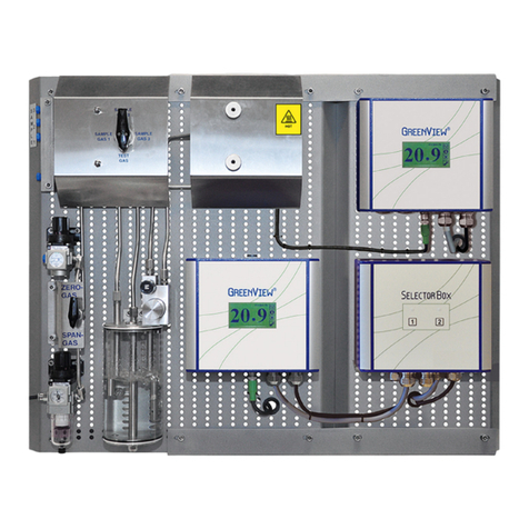
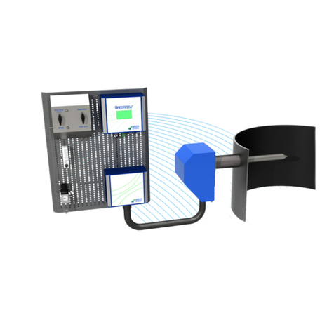
System Installation
8
3.3 Safety Aspects
Attention
Make sure to follow the operating instructions!
Read the manual before operating and servicing the system.
Hot sensor/probe!
The sensor/probe is hot and can cause severe burning of personnel if not handled with
care.
Installation and operation!
It should be pointed out that installation and operation of the G4100 NOX/O2Analyzing
System and associated equipment must be carried out by skilled, trained, and certified
personnel, and that Green Instruments A/S does not take any responsibility for the opera-
tion of the system and associated equipment whatsoever. The successful and safe opera-
tion of this equipment is dependent upon proper handling, installation, operation, and
maintenance.
Recycling!
Please do not dispose the G4100 NOX/O2Analyzing System with regular refuse. Disposal
should be in accordance with the requirements of the current statutory regulations.
3.4 Ejector Probe
The ejector probe is supplied with a mounting socket, gasket, sample tube, connection for
ejector air, connection for test gas and back-flushing air, sensor, and housing with mount-
ing plate.
The ejector probe has a small air operated ejector, which will propel the sample gas into
the sensor and back into the stack. The sample gas flow is drawn through the sample fil-
ter element into the sensor area via a narrow passage securing quick response time. The
sample gas velocity and responding time is controlled by the flow of the ejector air.
The gas, which passes the ejector probe, must represent the gas to be tested. Holes and
leaks in the gas ducting system before and after the probe may influence the accuracy of
the measurement.
The ejector probe shall be placed so that it is protected against mechanical damage. The
flue gas temperature cannot exceed the given temperature limit of the ejector probe.
When welding the mounting socket to the stack, make sure that the mounting plate of the
ejector probe is mounted with the sampling hose connection facing down and the ejector

G4100 NOx/O2 Analyzing System
9
probe protection house mounted in a vertical position of the stack. The insert length of
the ejector probe (250-300 mm) should be greater than 10 % of the duct diameter. See
26H26HFigure 3-1 for the installation layout of the ejector probe.
Exhaust Duct
Distance to the next upstream bent:
min. 3 duct diameters
Distance to the engine/turbo charger:
min. 10 duct diamters
Distance to the outlet:
min. 3 duct diamters
Distance to the next downstream bent:
min. 1 duct diameters
Sample to be drawn from the inner 80% of
the duct diameter.
NOx/O2
Probe
3
Umbilical
Cord
Insulation
Insulation
Figure 3-1: Installation layout of the ejector probe
The figure below shows the dimensions of the ejector probe.

System Installation
10
Figure 3-2: Ejector probe dimensions
The figure below shows the dimensions of the board.

G4100 NOx/O2 Analyzing System
11
Figure 3-3: Analyzing Board with G41 NOX/O2Analyzer mounted on board

System Installation
12
3.5 Analyzing Board
3.5.1 Mounting Panel
The analyzer board has two angle iron mounting brackets. The brackets are made of or-
dinary mild steel and can be welded or bolted directly to a chosen location structure as
required.
Figure 3-4: The G4100 NOX/O2analyzing board
The two mounting brackets are mounted horizontal and parallel with a distance of 580
mm.
When the analyzing board and the ejector probe are installed in appropriate locations, the
instrument air and power can be connected as described below.
The figure below shows the piping and connection of the system.

G4100 NOx/O2 Analyzing System
13
Figure 3-5: Piping and connection diagram
3.5.2 Air Supply Connection
For air ejection, back-flushing, and zero calibration, the instrument air is connected di-
rectly to the air supply filter regulator. The filter regulator has a filter and a drain. The air
supply connection to the filter regulator is a 1/8” BSP female connection.
The pressure of the air supply must not exceed 8 bar. To see the layout of the analyzing
board see 27H27HFigure 3-3.

System Installation
14
3.5.3 Span NOXGas Connection
For span calibration, span NOXgas with a certain percent of NOXand without the content
of O2is connected to the span NOXgas port. The connection is arranged on the left upper
corner of the analyzing board. The connection is a 1/8” BSP female connection.
The pressure of the Span NOX gas must not exceed 1 bar. The gas flow should be approx-
imately 0.5…1 l/m. To see the layout of the analyzing board see 28H28HFigure 3-3.
3.5.4 Analyzer and Electrical Connections
The G41 NOX/O2Analyzer is mounted on the right upper corner of the analyzing board.
To see the layout of the analyzing board see 29H29HFigure 3-3.
The instructions for electrical connections are described in the G41 NOx/O2Analyzer
manual.

G4100 NOx/O2 Analyzing System
15
4Commissioning
Before starting the system for the first time after completing the installation, please check
the installation and setup of the system.
4.1 Installation Checks of the Sampling Board
•Check that the ejector probe is installed in accordance with the instructions i.e. in a
suitable location that represents the gas to be tested. Make sure there is no leaks and that
the installation is in accordance with good installation practice.
•Check that the air supply is connected to the air supply filter regulator without leak-
ing and in accordance with good installation practice.
•Re-check all connections to make sure there is no air leaking. A leaking connection
will result in a loss of air or calibration gas and may result in poor calibration.
4.2 Commissioning of the Analyzer
Check that all electrical connections and analyzer settings are correct according to section
3110H33 and 5 in the G41 NOx/O2Analyzer manual.
4.3 Start of Systems
Using the G41 NOx/O2 Analyzer manual, follow the instructions for commissioning of the
analyzer and start the system. For calibration, follow the instructions in section 6.

Operation
16
5Operation
5.1 Calibration Mode
In the calibration mode (both Zero and Span), the selector valve must stay at the Cali-
bration position.
For zero calibration
•Turn the selector valve to Zero position.
•Check that the instrument air (zero NOXgas) is connected to the air supply filter
regulator.
•The pressure of the zero NOXgas must not exceed 8 bar and should be reduced to
0.3-1 bar at the air supply filter regulator station. The flow of zero NOXgas should be
approximately 0.5…1 l/min. which can be adjusted at the calibration flow meter.
For span calibration
•Turn the selector valve to Span position.
•Check that the span NOXgas is connected to the span NOXgas connection.
•The pressure of the span NOXgas should be approximately 1 bar. The flow of the
calibration gases should be approximately 0.5…1 l/min. which can be adjusted at the cal-
ibration flow meter, or at the fixed flow valve of the test gas bottle.
After calibration, remember to turn both selector valves back to the Operation position.
5.2 Measurement Mode
In the measurement mode, both selector valves must point to the Operation position.
To adjust the sample air flow, you have to adjust the flow of the ejector air at the sam-
pling flow meter. In the normal condition, the ejector air flow shall be approximately 2
l/min. at the pressure of 1 bar. If you need more suction, see section 116H2 for ejector probe
specifications.
The instrument air for back-flushing is regulated by the solenoid valve which is con-
trolled by the analyzer. For back-flushing, the solenoid valve will be opened automatical-
ly to allow the ejector probe back-flushing with high air flow. To set up the back-flushing
interval, see the instruction in the analyzer manual.

G4100 NOx/O2 Analyzing System
17
6Routine Maintenance
6.1 Air Flow System
Routine inspection and maintenance of the air flow system and connections is required to
make sure no gas is leaking from the system. It is important that air flow and pressure are
stable. Failure to periodically inspect and maintain the air flow system and connections
may lead to imprecise analyzer readings and thus a malfunction of the system.
Make sure that the instrument air that is supplied at the air supply filter regulator is max-
imum 8 bar and has a temperature of maximum 60 oC. Always prevent ultraviolet rays
from reaching the air supply filter regulator.
Before cleaning and servicing the air flow system, depressurize the air supply filter regu-
lator. When cleaning do not use an adhesion of organic solvents to the air supply filter
regulator.
The flow meter and the control valve do not require any special maintenance. Dirt and oil
on the surface of the flow meters are to be removed carefully using neutral detergent and
a clean dry rag.
6.2 Sensor
Attention
The analyzer must be turned off and the air supply must be disconnected before you
start changing the sensor.
If you remove the sensor while there is exhaust gas in the stack, there is a risk that
hot exhaust gas will come out of the sensor house.
The probe and the sensor are hot and can cause severe burning of personnel if not
handled with care.
To change the sensor, please go through the following steps:
•Turn off the analyzer and disconnect the air supply.
•Unscrew the nuts and remove the blue cover plate of the ejector probe.
•To disconnect the sensor electronic control unit (ECU) press the small button on the
plug at the end of the cable to the ECU and pull out the plug.

Routine Maintenance
18
•To dismount the ECU, loosen the two nuts on the back of the mounting plate.
•Use a spanner to loosen the sensor.
•Insert a new sensor into the sensor house.
•Mount the ECU back on the mounting plate.
•Reconnect the cable to the ECU.
Looking from side
Screws on the front
of the mounting
plateto remove the
probe from the stack Sensor electronic
control unit (ECU)
Figure 6-1: Ejector probe
6.3 Ejector Probe
The probe filter element is normally cleaned by back-flushing. The period between back-
flushings depends on the actual flue gas condition and how dirty the filter gets.
Regular back-flushing will normally keep the filter clean. However, a slow response to
NOX/O2changes in the flue gases indicates that the ejector probe filter or the ejector
probe venturi air nozzle may be contaminated. In that case, manual cleaning of the ejec-
tor probe is required.

G4100 NOx/O2 Analyzing System
19
WARNING
The analyzer must be turned off and the air supply must be disconnect-ed before
you start working with the probe.
If you remove the ejector probe while there is exhaust gas in the stack, there is a
risk that hot exhaust gas will come out of probe hole.
The probe and the sensor are hot and can cause severe burning of personnel if not
handled with care.
To clean the ejector probe, start by removing the ejector probe from the stack:
•Turn off the analyzer and disconnect the air supply.
•Unscrew the nuts and remove the blue cover plate of the ejector probe.
•Use a spanner to loosen the sensor. Unplug the sensor and the two sampling tubes.
Remember that the sensor can be extremely hot!
•Unbolt the 6 bolts at the bottom of the probe head bottom and pull out the ejector
probe.
Cleaning the probe filter element:
•To clean the probe filter element manually, remove the filter element by unscrew-
ing the filter bolt.
•Clean or change the filter.
Cleaning the ejector probe venturi air nozzle:
•Unbolt the red bolt on the probe head top and pull the ejector probe venturi air noz-
zle out.
•Clean the ejector probe venturi air nozzle with pressurized instrument air. The gas
canals in the ejector probe head top can also be cleaned with pressurized instrument air.

Routine Maintenance
20
Figure 6-2: Ejector probe –removing the venture air nozzle
•After cleaning put the ejector probe venturi air nozzle back in place and insert the
ejector probe back into the mounting socket.
•Place the blue cover plate back to the probe.
Other manuals for G4100
1
Table of contents
Other GREEN INSTRUMENTS Measuring Instrument manuals

GREEN INSTRUMENTS
GREEN INSTRUMENTS G4100 User manual

GREEN INSTRUMENTS
GREEN INSTRUMENTS G4130 NOX/O2 User manual

GREEN INSTRUMENTS
GREEN INSTRUMENTS G36p User manual

GREEN INSTRUMENTS
GREEN INSTRUMENTS G3621A/P User manual

GREEN INSTRUMENTS
GREEN INSTRUMENTS G3600 User manual

GREEN INSTRUMENTS
GREEN INSTRUMENTS Maritime G6100 User manual

GREEN INSTRUMENTS
GREEN INSTRUMENTS G3620A User manual

GREEN INSTRUMENTS
GREEN INSTRUMENTS Maritime G6200 User manual