7
S-176-9-E
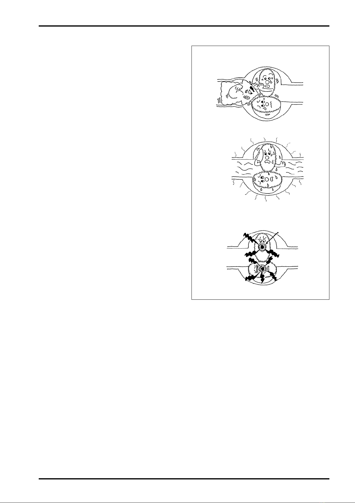
Excessive flow Rapid flow variation
Take precautions
against bearing burn!!
Rapid temperature variation
××
×
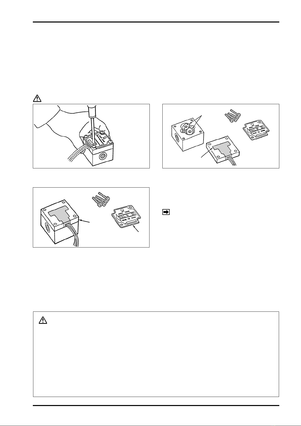
5.2 Operating Precautions
(1) When changing owrates:
In applications where the owrate varies or
where shutoff valve opening and closure takes
place in batch operation, avoid rapid changes
in owrate across the meter.
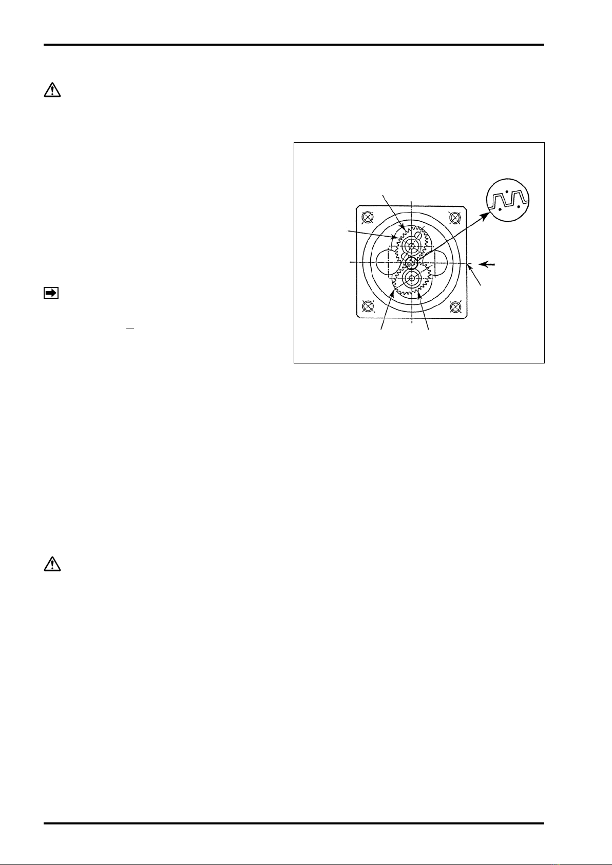
Operating the meter at owrates in excess of
the maximum allowable owrate will nullify the
guaranteed accuracy, reduce the meter life and
may result in faulty conditions, such as burn
of bearings or rotor-to-measuring chamber
contact.
(2) Where the temperature of metered uid
changes:
Avoid rapid temperature changes in the meter.
Temperature changes of the uid in the meter
should be held with in 3℃ perminute.
Extra care should be used particularly when
making a ow measurement in batch operation
without the provision of heat tracing of the
tubing where the fuid temperature differs from
atmospheric temperature.
If rapid temperature changes are anticipated,
heat trace the tubing assembly as well as
the meter.
(3) Liquids of low steam pressure:
Liquids with low viscosity and low steam
pressure can easily vaporize and their
temperature and pressure should therefore
be strictly controlled.
During operation, the temperature of bearings
in the meter usually runs higher than that of
the metered uid. Vapors around the bearings
can present problems, such as unusual noise
and bearing seizure.
(4) Highly corrosive liquids:
When you make a measurement of highly
corrosive liquids, appropriate materials should
be used for tanks and tubing assembly.
Heterogeneous materials originally contained
in the metered fluid, or certain substances
that have leaked out of the tanks and/or
tubing of inappropriate materials, may lead to
costly downtime, as a result of locked rotors,
for example, when they are allowed into the
measuring chamber.