oventrop Regtronic S-Bus User manual

*11202533*
11202533
Premium Armaturen + Systeme
„Regtronic S-Bus“ Schnittstellenadapter für PWM / 0-10V
Einbau- und Betriebsanleitung für Fachpersonal
DE

|2
Irrtum und technische Änderungen vorbehalten
Inhaltsverzeichnis
Sicherheitshinweise.................................................. 2
Übersicht................................................................... 3
Technische Daten .................................................... 3
1. Montage .............................................................. 4
2. Anschluss ............................................................ 5
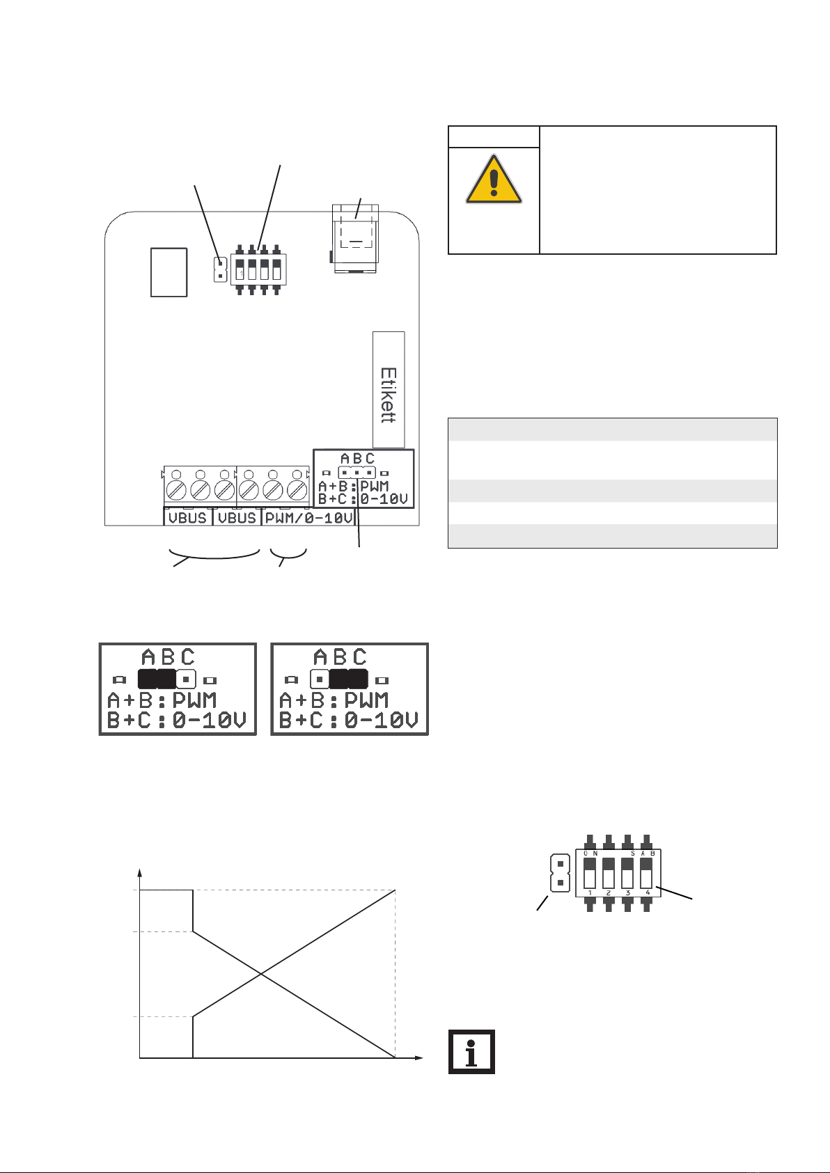
3. Einstellung der Ausgangsart ............................. 5
4. Invertierung der PWM-Signalausgabe............. 5
5. DIP-Schalter zur Relaisadressierung ............... 6
6. Inbetriebnahme.................................................. 7
6.1 Initialisierungsphase ............................................................7
6.2 Anzeige des adressierten Relais.......................................7
6.3 Fehlermeldung......................................................................7
Sicherheitshinweise
Bitte beachten Sie diese Sicherheitshinweise genau,um Ge-
fahren und Schäden für Menschen und Sachwerte auszu-
schließen.
Vorschriften
Beachten Sie bei allen Arbeiten die nationalen und regio-
nalen gesetzlichen Vorschriften, Normen, Richtlinien und
Sicherheitsbestimmungen.
Symbolerklärung
Signalwörter kennzeichnen die Schwere der Gefahr, die
auftritt, wenn sie nicht vermieden wird.
WARNUNG bedeutet, dass schwere Personenschäden
oder sogar Lebengefahr auftreten können.
ACHTUNG bedeutet, dass Sachschäden auftreten kön-
nen.
Angaben zum Gerät
Bestimmungsgemäße Verwendung
Der „S-Bus Schnittstellenadapter“ darf nur für die dreh-
zahlgeregelte Ansteuerung einer Pumpe in Verbindung mit
einem elektronischen Regler für solarthermische Anlagen
über den S-Bus unter Berücksichtigung der in dieser Anlei-
tung angegebenen technischen Daten verwendet werden.
Die bestimmungswidrigeVerwendung führt zum Ausschluss
jeglicher Haftungsansprüche.
CE-Konformitätserklärung
Das Produkt entspricht den relevanten Richt-
linien und ist daher mit der CE-Kennzeichnung
versehen.
Hinweis
Hinweise sind mit einem Informationssymbol
gekennzeichnet.
Entsorgung
• Das Verpackungsmaterial des Gerätes umweltgerecht
entsorgen.
• Altgeräte müssen durch eine autorisierte Stelle umwelt-
gerecht entsorgt werden.Auf Wunsch nehmen wir Ihre
bei uns gekauften Altgeräte zurück und garantieren für
eine umweltgerechte Entsorgung.
ÎTextabschnitte, die mit einem Pfeil gekennzeichnet sind,
fordern zu einer Handlung auf.
WARNUNG!
Warnhinweise sind mit einem
Warndreieck gekennzeichnet!
ÎEs wird angegeben,wie die Ge-
fahr vermieden werden kann!
Hinweis
Starke elektromagnetische Felder können die
Funktion des Geräts beeinträchtigen.
ÎSicherstellen, dass das Gerät keinen starken
elektromagnetischen Strahlungsquellen aus-
gesetzt ist.

• Drehzahlregelung von Hocheffizienzpumpen für
Regler ohne integrierten PWM-Ausgang
• Einfach zu installieren
• Umschaltbar von PWM- auf 0-10-V-Signal
• Mit 7-Segment-Anzeige
3 |
Übersicht
„S-Bus Schnittstellenadapter“
Der „S-Bus Schnittstellenadapter“ dient der Ansteuerung
der Pumpe über ein PWM- oder 0-10-V-Signal. Der Adap-
ter empfängt über den S-Bus Drehzahlinformationen des
Reglers. Die Drehzahl wird in ein PWM- oder Gleichspan-
nungssignal umgewandelt und auf den entsprechenden
Klemmen ausgegeben.
Ein der Drehzahl entsprechendes Signal steht nur zur Ver-
fügung, wenn das entsprechende Relais zur Drehzahlrege-
lung ausgelegt ist.Ansonsten steht je nach Relaisstellung ein
Signal für den Ein- oder Aus-Zustand an.
Technische Daten
Gehäuse: Kunststoff
Schutzart: IP 20 (EN 60529)
Umgebungstemperatur: 0 …70°C
Abmessungen: 95 × 70 × 25 mm
Einbau: Wandmontage (optional)
Anzeige: 7-Segment-Anzeige
Versorgung:
Eingangsspannung Steckernetzteil:
100… 240V~/ 50… 60 Hz
Eingangsspannung Adapter:
12V , 1 A
5.5 x 2.1 mm
Schnittstelle: S-Bus
Lieferumfang
1 × Steckernetzteil 12 V /1 A/5.5 x 2.1 mm
1 × S-Bus-Leitung 1,5 m
1 × Zubehörbeutel mit
2 × Schraube und Dübel
4 × selbstklebende Gummifüßchen
oventrop
Artikel-Nr. 1369531
Input: DC 12 V / 1 A
IP20
Adapter S-Bus PWM
0-10 V
Adapter S-Bus
-+

|4
Die Montage darf ausschließlich in trockenen Innenräumen
erfolgen. Bei der Installation der Netzanschlussleitung und
der Signalleitungen auf getrennteVerlegung achten.
Der Schnittstellenadapter ist klein und leicht, so dass eine
Wandmontage nicht unbedingt notwendig ist. Er kann auf
einer geeigneten Oberfläche abgelegt werden (zulässige
Umgebungstemperatur beachten!).
Es liegen vier selbstklebende, rutschfeste Gummifüßchen
bei, die bei Bedarf in den entsprechenden Vertiefungen an
der Gehäuseunterseite angebracht werden können, um
eine sichere Ablage des Geräts ohne Wandmontage zu ge-
währleisten.
Falls eineWandmontage vorgenommen werden soll, folgen-
dermaßen vorgehen:
ÎGewünschte Position für die Aufhängung auf dem Un-
tergrund markieren.
ÎBohrloch vorbereiten und beiliegenden Dübel mit zuge-
höriger Schraube vormontieren.
ÎGehäuse am Aufhängungspunkt einhängen.
ÎPosition für die Befestigungsschraube auf dem Unter-
grund markieren (Lochabstand 70 mm).
ÎUnteres Bohrloch vorbereiten und Dübel setzen.
ÎGehäuse oben einhängen und mit unterer Befestigungs-
schraube fixieren.
Für die Wandmontage muss das Gehäuse nicht geöffnet
werden. Die Öffnung des Gehäuses ist nur für den Zugang
zu den Klemmen erforderlich.
ÎUm das Gehäuse zu öffnen, die Verschlussschraube lö-
sen und das Gehäuseoberteil abnehmen.
ÎUm das Gehäuse wieder zu verschließen,Gehäuseober-
teil wieder aufsetzen undVerschlussschraube festziehen.
1. Montage
ACHTUNG!
Elektrostatische Entladung!
Elektrostatische Entladung kann zur Schä-
digung elektronischer Bauteile führen!
ÎVor dem Berühren des Ge-
häuseinneren für Entladung sor-
gen. Dazu ein geerdetes Bauteil
(z. B.Wasserhahn, Heizkörper o.
ä.) berühren.
Hinweis
Die Spannungsversorgung der Pumpe kann ex-
tern erfolgen.
Anschlussskizze
Vorderansicht
Rückansicht
Öffnung für
die Befestigungs-
schraube
Aufhängung
Vertiefungen
für die Gum-
mifüßchen
Verschluss-
schraube
Gehäuseoberteil
Gehäuseunterteil
230V~
S-Bus Datenleitung PWM/0-10V
S-Bus
Adapter

5 |
2. Anschluss
S-Bus-Anschluss an den Klemmen:
S-Bus (1 + 2; 3 + 4) S-Bus-Eingang/ -Ausgang,
Polung beliebig
Anschluss der Pumpe an den Klemmen:
Signalausgang (5) PWM oder 0-10 V
GND (6) Masse/ Erde
S-Bus-Klemmen Signalausgang
Jumpersteckplatz für
die Umstellung von
PWM auf 0-10V
Jumpersteckplatz für die
Invertierung des PWM-Signals
(siehe Kap.3)
DIP-Schalter zur Adressierung des
Signalausgangs (siehe Kap. 4.)
Über den zweipoligen Jumpersteckplatz links neben den
DIP-Schaltern kann das ausgegebene PWM-Signal inver-
tiert werden.
3. Einstellung der Ausgangsart
Jumpersteckplatz
für die Invertierung
des PWM-Signals
DIP-Schalter zur
Adressierung der
Signalausgänge
Der „S-Bus Schnittstellenadapter“ wird mit bereits ange-
schlossener S-Bus-Leitung geliefert.
Das zweite S-Bus-Klemmenpaar kann für den Anschluss
von weiterem S-Bus-Zubehör genutzt werden.
Für den Netzanschluss des Schnittstellenadapters liegt ein
Steckernetzteil bei.
Die Pumpe wird an den Signalausgang (Klemmen 5 und 6,
siehe Tabelle unten) angeschlossen.
ACHTUNG!
Kurzschluss!
Ein Kurzschluss kann zur Schädigung
elektronischer Bauteile führen!
ÎNetzverbindung erst herstellen,
wenn die Klemmen fertig ver-
drahtet sind und das Gehäuse
wieder verschlossen ist!
(1) (3)(2) (4)
8.
Die Mindestdrehzahl liegt bei 30% (siehe Abbildung links).
30% 100%PWM %
30%
100%
Drehzahl
70%
Hinweis
Bei jedem Einschaltvorgang wird die Pumpe zu-
nächst für wenige Sekunden mit 100 % Dreh-
zahl angesteuert, bevor die flexible Drehzahlre-
gelung einsetzt.
(5) (6)
Anschlussbuchse für
das Steckernetzteil
4. Invertierung der PWM-Signalausgabe
Über den dreipoligen Jumper rechts neben den Anschluss-
klemmen wird festgelegt, ob am Signalausgang ein PWM-
oder 0-10-V-Signal ausgegeben werden soll.
Die drei Jumperpole sind mit A, B und C beschriftet.
Jumperposition A+B = PWM-Signal (Werkseinstellung)
Jumperposition B+C = 0-10-V-Signal
Signalart ändern:
ÎDen Jumper aus dem Steckplatz ziehen und entspre-
chend der gewünschten Signalart wieder aufstecken.
Jumperstellung für PWM-Signal Jumperstellung für 0-10-V-Signal
Nicht aufgesteckter Jumper
Das 0-10-V-Signal wird von der Invertierung des Signals
nicht beeinflusst.
Aufgesteckter Jumper
(Werkseinstellung)

|6
5. DIP-Schalter zur Relaisadressierung
Über die DIP-Schalter wird eingestellt, von welchem Re-
lais die Drehzahl-Information in ein entsprechendes Signal
umgewandelt werden soll. Jedem Relais ist eine bestimmte
Position der DIP-Schalter vorgegeben.
Im Lieferzustand ist das Relais 1 als Adresse eingestellt.
ÎUm die Adressierung zu verändern, die DIP-Schalter in
die dem gewünschten Relais entsprechende Position
stellen.
In den folgendenAbbildungen ist die Stellung der DIP-
Schal-
ter für das jeweilige Relais dargestellt.
Relais 2
Relais 1 (Werkseinstellung) Relais 3
Relais 4 Relais 5 Relais 6
Relais 7 Relais 8 Relais 9
Relais 10
Relais 13
Relais 11
Relais 14
Relais 12
Relais 15
Relais 16
Das adressierte Relais wird im Betrieb über die 7-Segment-
Anzeige angezeigt. Siehe dazu auch Kap. 6.2.

7 |
Das mit den DIP-Schaltern adressierte Relais wird durch die
7-Segment-Anzeige auf der Vorderseite des Adapters ange-
zeigt.
Da die Anzeige einstellig ist, wird die vordere Dezimalstelle
bei den Relais 10-16 durch einen Punkt ersetzt:
Wenn ein Fehler auftritt, blinkt in der Anzeige ein Fehler-
code:
a= Der Ausgang wurde falsch adressiert. Das angesteu-
erte Relais ist nicht vorhanden.
ÎEin gültiges Relais adressieren.
f= Die S-Bus-Verbindung ist fehlerhaft.
ÎDie S-Bus-Leitung überprüfen.
u= Der angeschlossene Regler wird vom Schnittstellen-
adapter nicht erkannt.
ÎCa. eine Minute abwarten. Falls die Fehlermeldung nicht
verschwindet, den Hersteller kontaktieren.
6. Inbetriebnahme Der „S-Bus Schnittstellenadapter“ verfügt über eine 7-Seg-
ment-Anzeige, über die der Betriebszustand sowie das aus-
gewählte Relais angezeigt wird.
1= Relais 1 Regtronic RM
2= Relais 2
3= Relais 3 Regtronic RX
4= Relais 4
5= Relais 5
6= Relais 6
7= Relais 7
8= Relais 8
9= Relais 9
0. = Relais 10
1. = Relais 11
2. = Relais 12
3. = Relais 13
4. = Relais 14
5. = Relais 15
6. = Relais 16
6.1 Initialisierungsphase Wenn der Schnittstellenadapter angeschlossen wird,durch-
läuft er eine kurze Initialisierungsphase.
Währenddessen zeigt die Anzeige zunächst die Fehlermel-
dung f, dann die Fehlermeldung uan, bis der angeschlosse-
ne Regler erkannt wurde. Nach kurzerWartezeit erscheint
die Anzeige des adressierten Relais.
Falls die Anzeige von foder unicht verschwindet oder statt
der Nummer des adressierten Relais ein aerscheint, liegt
ein Fehler vor. Für nähere Informationen zu den Fehlermel-
dungen und demVerhalten im Fehlerfall siehe Kap. 6.3.
6.2 Anzeige des adressierten Relais
6.3 Fehlermeldung

Technische Änderungen vorbehalten.
136953181 11/2015
OVENTROP GmbH & Co. KG
Paul-Oventrop-Straße 1
D-59939 Olsberg
Telefon +49(0) 2962 82-0
Telefax +49(0)296282-400
E-Mail mail@oventrop.de
Internet www.oventrop.com
Eine Übersicht der weltweiten
Ansprechpartner finden Sie unter
www.oventrop.de.

Valves, controls + systems
”Regtronic S-Bus“ interface adapter PWM / 0-10V
Installation and operating instructions for the specialised installer
EN

|10
Table of contents
Safety advice........................................................... 10
Overview................................................................. 11
Technical data......................................................... 11
1. Mounting.......................................................... 12
2. Connection ...................................................... 13
3. Adjusting the signal type................................ 13
4. Inverting the PWM signal .............................. 13
5. DIP switches.................................................... 14
6. Commissioning ............................................... 15
6.1 Initialisation phase........................................................... 15
6.2 Indication of the selected relay.................................... 15
6.3 Error message.................................................................. 15
Description of symbols
Disposal
Signal words describe the danger that may occur, when it
is not avoided.
WARNING means that injury, possibly life-threatening
injury, can occur.
ATTENTION means that damage to the appliance can
occur.
• Dispose of the packaging in an environmentally sound
manner.
• Dispose of old appliances in an environmentally sound
manner. Upon request we will take back your old appli-
ances bought from us and guarantee an environmentally
sound disposal of the devices.
Information about the product
Proper usage
The ”S-Bus interface adapter“may only be used for the
speed control of a pump in combination with an electronic
controller for solar thermal systems via the S-Bus in com-
pliance with the technical data specified in these instruc-
tions. Improper use excludes all liability claims.
CE-Declaration of conformity
The product complies with the relevant di-
rectives and is therefore labelled with the CE
mark.
Note
Notes are indicated with an information sym-
bol.
ÎArrows indicate instruction steps that should be car-
ried out.
Safety advice
Please pay attention to the following safety advice in order
to avoid danger and damage to people and property.
Instructions
Attention must be paid to the valid local standards, regula-
tions and directives!
WARNING! Warnings are indicated with a
warning triangle!
ÎThey contain information on
how to avoid the danger de-
scribed.
Note
Strong electromagnetic fields can impair the
function of the device.
ÎMake sure the device is not exposed to
strong electromagnetic fields.
Subject to technical change. Errors excepted.

11 |
Overview
”S-Bus interface adapter“
The ”S-Bus interface adapter“ is used for the speed con-
trol of a pump via a PWM or 0-10 V signal.Via the S-Bus
the adapter receives information from the controller about
speed.The speed is converted into a PWM or direct volt-
age signal and put out to the corresponding terminals.
A signal corresponding to the speed is only available if the
corresponding relay is designed for pump speed control.
Otherwise, a signal – depending on the position of the
relay – for the on or off state is transmitted.
Technical data
Housing: plastic
Protection type: IP 20 (EN 60529)
Ambient temperature: 0…70°C
Dimensions: 95 × 70 × 25 mm
Mounting: Wall mounting is possible (but not required)
Display: 7-segment LED display
Power supply:
Mains adapter power supply: 100… 240V~/50… 60 Hz
Interface adapter power supply: 12V /1 A
5.5 × 2.1 mm
Interface: S-Bus
Included:
1 × mains adapter 12V /1 A /5.5 x 2.1 mm
1 × S-Bus cable 1.5 m
1 × accessory bag containing
2 × screw and wall plug
4 × self-adhesive, skid-proof rubber pad
• Speed control of high-efficiency pumps for
controllers without integrated PWM outputs
• Easy to install
• Convertible from PWM to 0-10V signal
• With 7-segment LED display
oventrop
Artikel-Nr. 1369531
Input: DC 12 V / 1 A
IP20
Adapter S-Bus PWM
0-10 V
Adapter S-Bus
-+

|12
1. Mounting
The unit must only be located in dry interior locations. It
is not suitable for installation in hazardous locations. Please
pay attention to separate routing of sensor cables and
mains cables.
The interface adapter is light and small enough to not re-
quire any form of mounting. It can be placed on a suitable
surface (pay attention to the ambient temperature!).
Four self-adhesive,skid-proof rubber pads are included with
the adapter. If necessary, these can be affixed to the corre-
sponding molds on the base part of the housing to ensure
a secure placement of the device without wall mounting.
If desired, the interface adapter can be mounted to a wall:
ÎMark the desired hanging position on the wall.
ÎDrill and prepare the hole with a wall plug and screw.
ÎHang the device onto the screw.
ÎMark the position for the mounting screw (distance to
hanging point centre: 70 mm).
ÎDrill and prepare a hole with a wall plug.
ÎHang the device and fasten it by means of the second
screw.
For wall mounting, opening the housing is not required.
Opening the housing is only required for access to the ter-
minals.
ÎTo open the housing, unscrew the cover screw and pull
off the upper part of the housing.
ÎTo close the housing again, relocate the upper part of
the housing and refasten the cover screw.
ATTENTION! ESD damage!
Electrostatic discharge can lead to
dam-
age to electronic components!
ÎTake care to discharge prop-
erly before touching the inside
of the device.To do so, touch a
grounded surface such as a ra-
diator or tap!
230V~
S-Bus PWM/0-10V
Note
An external mains connection to the pump can
be made.
Connection scheme
Front view
Back view
Opening for the
mounting screw
Hanging
Molds for the
rubber pads
Cover screw
Upper
part of the
housing
Base part of the
housing
S-Bus
adapter

13 |
2. Connection
S-Bus connection at the terminals:
S-Bus (1 + 2; 3 + 4) S-Bus input/output, either polarity
Pump connection at the terminals:
Signal output (5) PWM or 0- 10V
GND (6) Ground/Earth
3. Adjusting the signal type
The ”S-Bus interface adapter“ comes with a pre-connected
S-Bus cable.The second pair of S-Bus terminals can be used
for the connection of another S-Bus device.
Jumper slot for setting
the signal type (PWM
or 0-10V; see ch. 6)
Jumper slot for the inversion of
the PWM signal (see ch. 3.)
DIP switches for addressing the
signal output (see ch. 4.)
8.
ATTENTION! Short circuit!
A short circuit can lead to damage to
electronic components!
ÎFinish terminal connection and
close the housing before estab-
lishing the mains connection!
The interface adapter comes with a mains adapter for the
power supply.
The pump is to be connected to the signal output at the
terminals 5 and 6 (see table below).
Jumper slot for
the inversion of
the PWM signal
DIP switches for
addressing the
signal output
30% 100%PWM %
30%
100%
pump speed
70%
Note
Whenever the pump is switched on, it will be
run at 100 % speed for a few seconds before
the flexible pump speed control is effected.
S-Bus terminals Signal output
(1) (3)(2) (4) (5) (6)
By means of the two-pole jumper slot to the left of the DIP
switches, the PWM signal generated can be inverted.
Changing the factory setting:
The minimum pump speed is 30% (see figure to the left).
Connection socket for
the mains adapter
4. Inverting the PWM signal
The jumper to the right of the terminals is used for de-
termining whether a PWM signal or 0-10 V signal is to be
used.
The jumper poles are indicated with A, B and C.
Jumper position A+B = PWM signal (factory setting)
Jumper position B+C = 0-10-V-signal
Changing the signal type:
ÎPull the jumper out of the slot and insert it according to
the desired signal type.
Jumper position for PWM signal Jumper position for 0-10V signal
Jumper not connected
The 0-10 V signal is not affected by the signal inversion.
Jumper connected
(factory setting)

|14
5. DIP switches for relay allocation The adjusted relay transmits information on pump speed
which is then converted into a corresponding signal. The
relay is selected by means of the DIP switches. Each relay is
characterised by a certain position of the switches.
Relay 1 is selected by default.
ÎPut the DIP switches in the position appropriate for the
desired relay.
The following table shows the position of the DIP switches
for each relay,
Relay 2
Relay 1 Relay 3
Relay 4 Relay 5 Relay 6
Relay 7 Relay 8 Relay 9
Relay 10
Relay 13
Relay 11
Relay 14
Relay 12
Relay 15
Relay 16
During normal operation, the relay addressed will be dis-
played by the 7-segment-display. See chap. 6.2.

15 |
6. Commissioning The ”S-Bus interface adapter“ is equipped with a 7-seg-
ment LED display that can indicate the selected relay or the
current operational status.
1= Relay 1 Regtronic RM
2= Relay 2
3= Relay 3 Regtronic RX
4= Relay 4
5= Relay 5
6= Relay 6
7= Relay 7
8= Relay 8
9= Relay 9
0. = Relay 10
1. = Relay 11
2. = Relay 12
3. = Relay 13
4. = Relay 14
5. = Relay 15
6. = Relay 16
The relay addressed via the DIP switches is displayed by the
7-segment-LED at the front of the adapter.
As the LED can only indicate one figure, the decimal digit is
replaced with a dot when indicating relays 10 - 16:
If an error occurs, the display flashes an error code:
a= The output addressing is faulty. The relay addressed
does not exist.
ÎAddress a valid relay.
f= The S-Bus connection is faulty.
ÎCheck the S-Bus cable.
u= The controller connected is not recognised by the de-
vice.
ÎWait for about one minute. If the error code does not
disappear, contact the manufacturer.
When the interface adapter is connected to a controller
for the first time, a short initialisation phase will be run.
During this phase, the LED display flashes first the error
code f, then the error code uuntil the controller connect-
ed has been recognised.After a short time, the address of
the selected relay will be indicated.
If the error codes do not disappear or if an ais indicated
instead of the relay address, see chapter 6.3 for error code
descriptions and troubleshooting measures.
6.1 Initialisation phase
6.2 Indication of the selected relay
6.3 Error message

Subject to technical modification without notice.
136953181 11/2015
For an overview of our global
presence visit www.oventrop.com.

Robinetterie «haut de gamme» + Systèmes
«Regtronic S-Bus» Adaptateur interface PWM / 0-10V
Notice d’installation et d’utilisation pour les professionnels
FR

|18
Sommaire
Recommandations de sécurité ............................. 18
Vue d‘ensemble ...................................................... 19
Caractéristiques techniques ................................. 19
1. Montage ........................................................... 20
2. Branchement électrique ................................ 21
3. Réglage du signal de sortie ............................ 21
4. Inversion du signal de sortie PWM ............... 21
5. Réglage des interrupteurs DIP ...................... 22
6. Mise en service................................................ 23
6.1 Phase d‘initialisation........................................................ 23
6.2 Affichage du relais défini................................................ 23
6.3 Messages d’erreur........................................................... 23
Explication des symboles utilisés
Certains termes utilisés dans ce mode d‘emploi vous aver-
tissent des dangers potentiels auxquels vous vous exposez
en cas de non respect des consignes de sécurité énoncées.
Avertissement indique une situation présentant des
risques susceptibles de provoquer des bessures graves,voir
même d‘entraîner la mort.
Attention indique une situation susceptible de provoquer
des dommages matériels.
Indications concernant l‘appareil
Utilisation conforme aux dispositions du fabricant
«L’adaptateur S-Bus» doit s’utiliser uniquement en com-
binaison avec un régulateur électronique conçu pour les
installations de chauffage solaire thermique pour régler la
vitesse de pompes en tenant compte des données tech-
niques énoncées dans le présent mode d’emploi.
Toute utilisation non conforme aux prescriptions du fabri-
cant entraînera l‘annulation de la garantie.
Déclaration de conformité CE
Le marquage „CE“ est apposé sur ce produit,
celui-ci étant conforme aux dispositions com-
munautaires prévoyant son apposition.
Indication
Toute information importante communiquée
à l‘utilisateur est précédée de ce symbole.
Traitement des déchets
• Veuillez recycler l‘emballage de l‘appareil.
• Les appareils en fin de vie doivent être déposés auprès
d‘une déchèterie ou d‘une collecte spéciale de déchets
d‘équipements électriques et électroniques.
ÎLes paragraphes précédés d‘une flèche vous invitent à
agir sur l’appareil.
AVERTISSEMENT !
Les messages d‘avertisse-
ment sont précédés d‘un
triangle de signalisation !
ÎInstructions pour éviter
les dangers
Recommandations de sécurité
Veuillez lire attentivement les recommandations suivantes
afin d‘éviter tout dommage aux personnes et aux biens.
Prescriptions
Pour toute opération effectuée sur l‘appareil,veuillez pren-
dre en considération les règles, prescriptions et directives
concernées en vigueur!
Sous réserve d’erreurs et de modifications techniques.
Indication
Des champs électromagnétiques trop élevés
peuvent perturber le fonctionnement de l‘appa-
reil.
ÎVeillez à ne pas exposer ce dernier ni le sys-
tème à des champs électromagnétiques trop
élevés.

19 |
«Adaptateur interface S-Bus»
«L’adaptateur S-Bus»sert à régler la vitesse de pompes à
travers un signal PWM ou un signal de 0-10 V.Après avoir
reçu les informations relatives à la vitesse de la pompe par
la borne S-Bus, l‘adaptateur convertit ces dernières en si-
gnal PWM ou en signal de tension continue et les transmet
aux bornes correspondantes.
Les relais ne peuvent émettre des informations relatives à
la vitesse de la pompe que lorsqu‘ils sont conçus à cet effet.
Dans le cas contraire,ils n‘émettent que des signaux on/ off
selon leur position.
Caractéristiques techniques
Boîtier: en plastique
Type de protection: IP 20 (EN 60529)
Température ambiante: 0…70 °C
Dimensions: 95 × 70 × 25 mm
Montage: mural (optionnel)
Affichage: afficheur 7 segments
Alimentation:
Tension d‘entrée de l‘adaptateur secteur:
100… 240V~/ 50… 60 Hz
Tension d‘entrée de l‘adaptateur interface: 12V /1 A
5.5 × 2.1 mm
Interface: S-Bus
Fournitures
1 × adaptateur secteur 12V / 1 A /5.5 x 2.1 mm
1 × câble S-Bus (1,5 m)
1 × sachet d‘accessoires avec:
2 × vis et chevilles
4 × pieds antidérapants autoadhésifs en caoutchouc
Vue d‘ensemble
• Réglage de vitesse des pompes à haute efficacité
pour les régulateurs non dotés de sortie PWM
• Montage simple
• Commutateur de signal (PWM/0-10V)
• Afficheur 7 segments
oventrop
Artikel-Nr. 1369531
Input: DC 12 V / 1 A
IP20
Adapter S-Bus PWM
0-10 V
Adapter S-Bus
-+

|20
Réalisez le montage de l’appareil dans une pièce intérieure
sèche. Lors de l‘installation, veiller à maintenir le câble de
connexion au réseau électrique séparé du câble de trans-
mission des signaux.
En raison de la taille réduite de l‘appareil, il n‘est pas néces-
saire de l‘accrocher au mur. Celui-ci peut tout simplement
être posé sur une surface appropriée (veillez à respecter la
température ambiante admise!).
L‘adaptateur est livré avec quatre pieds antidérapants auto-
adhésifs en caoutchouc. Ceux-ci peuvent être collés dans
les cavités prévues à cet effet au dos de l‘appareil afin de
fixer celui-ci de manière optimale sur une surface plate.
L‘adaptateur interface peut également être fixé au mur:
Pour cela, suivez les indications suivantes:
ÎMarquez le point d‘accrochage sur le mur ou la paroi,
percez et introduisez la cheville et la vis dans le trou
correspondant.
ÎAccrochez le boîtier à la vis supérieure et marquez
le point de fixation inférieur (distance entre les deux
trous: 70 mm).
ÎPercez le mur ou la paroi et introduisez la cheville et la
vis dans le trou correspondant.
ÎAccrochez le boîtier à la vis supérieure et fixez-le avec
la vis inférieure.
Si vous accrochez l‘adaptateur au mur, il ne vous sera pas
nécessaire d‘ouvrir son boîtier. Ce dernier ne doit s‘ouvrir
que pour permettre l‘accès aux bornes de connexion.
ÎPour ouvrir le boîtier, dévissez la vis de fermeture et
détachez la partie supérieure de celui-ci.
ÎPour refermer le boîtier, placez la partie supérieure du
boîter sur la partie inférieure et vissez la vis de ferme-
ture.
1. Montage
ATTENTION !
Risque de décharges électrosta-
tiques !
Des décharges électrostatiques peuvent
endommager les composants électro-
niques de l’appareil !
ÎAvant de toucher l’intérieur
de celui-ci, éliminez l’électri
ci-
té statique que vous avez sur
vous en touchant un objet mis
à la terre tel qu’un robinet ou
un radiateur.
230V~
S-Bus PWM/0-10V
Indication
La pompe peut être alimentée par une source
d‘alimentation externe.
Vue schématique des branchements
vue de face
vue de dos
orifice pour la
vis de fixation
oeillet de
suspension
pieds antidérapants
en caoutchouc
vis de fermeture
partie supérieure
du boîtier
partie inférieure
du boîtier
Adaptateur
S-Bus
This manual suits for next models
1
Table of contents
Languages: