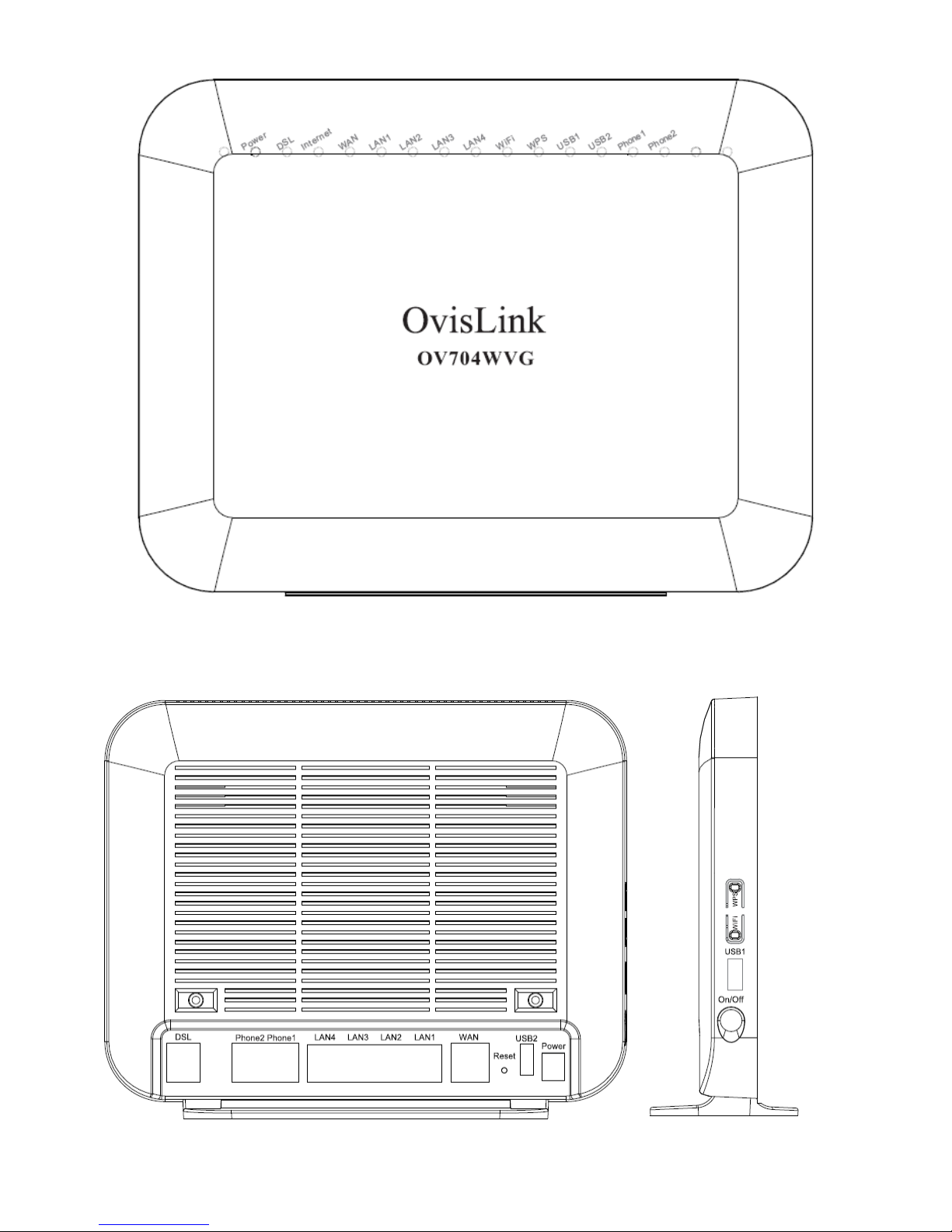
Ovislink OV704WVG User manual

OvisLink OV704WVG
Quick Installation Guide


1 Hardware Description and
Installation
Note:
The figures in this document are for reference only.
1.1 Hardware Description
Figure 1 Front panel
The following table describes the indicators on the front
panel.
Indicator Color Status Description
Power
Green
On The device is powered on and
the device operates normally.
Blink The software is upgrading.
Off The device is powered off.
Red On The device is initiating.
Blink The software is upgrading.
DSL Green On DSL link has established.
Blink The DSL line is training.

Indicator Color Status Description
Off Device is powered off.
Internet Green
On Internet is synchronized
successfully in the route mode.
Blink Internet data is being
transmitted.
Off Ethernet interface is
disconnected.
Red On Authentication has failed.
WAN Green
On
The WAN interface is connected
to the Ethernet cable.
Blink Network data is transmitting.
Off The WAN interface is not
connected to the Ethernet cable.
LAN
1/2/3/4 Green
On The Ethernet interface is
connected.
Blink Data is being transmitted
through the Ethernet interface.
Off The Ethernet interface is
disconnected.
WiFi Green
On WIFI is enabled.
Blink Data is being transmitted
through the wireless interface.
Off WIFI is disabled.

Indicator Color Status Description
WPS Green
On Connection succeeds under
Wi-Fi Protected Setup.
Blink Negotiation is in progress under
Wi-Fi Protected Setup.
Off Wi-Fi Protected Setup is
disabled.
USB1/2 Green
On The connection of 3G or USB
flash disk has established.
Blink Data is being transmitted.
Off No signal is detected.
Phone1/2 Green
Off No FXS signal is detected.
Blink The user data is passing
through FXS port.
On The FXS interface is ready to
work.

1.2 Rear Panel and Side Panel
Figure 2 Rear panel Figure 3 Side
panel

The following table describes the interfaces and the buttons.
Interface Description
DSL RJ-11 port. Connect the router to DSL
connector or splitter through telephone cable.
Phone1/2 RJ-11 port, using the telephone cable to
connect the telephone set.
LAN 4~1 RJ-45 port, for connecting the router to a PC or
another network device.
WAN For connecting Ethernet cable to provide
Ethernet uplink.
Reset
Press the button for at least 1 second and then
release it. System restores the factory default
settings.
USB1/2 USB port, for connecting the 3G network card
or other USB storage devices.
Power Power interface, for connecting the power
adapter.
On/Off Power switch.
WiFi WiFi switch, for enabling or disabling the WiFi
function.
WPS
This button is used for enabling WPS PBC
mode. If WPS is enabled, press this button, and
then the wireless router starts to accept the
negotiation of PBC mode.

Warning:
Do not press the Reset button unless you want to clear the
current settings. The Reset button is in a small circular hole
on the rear panel. If you want to restore the default settings,
please press the Reset button gently for 1 second with a
fine needle inserted into the hole and then release the
button. The system reboots and returns to the factory
defaults.
2 Hardware Installation
2.1 Choosing the Best Location for Wireless
Operation
Many environmental factors may affect the effective wireless
function of the DSL Router. If this is the first time that you set
up a wireless network device, read the following information:
The access point can be placed on a shelf or desktop,
ideally you should be able to see the LED indicators in the
front, as you may need to view them for troubleshooting.
Designed to go up to 100 meters indoors and up to 300
meters outdoors, wireless LAN lets you access your network
from anywhere you want. However, the numbers of walls,
ceilings, or other objects that the wireless signals must pass
through limit signal range. Typical ranges vary depending on

types of materials and background RF noise in your home or
business.
2.2 Connecting the Device
Step 1 Connect the DSL port of the router and the
Modem port of the splitter with a telephone
cable; connect the phone to the phone port of
the splitter through a cable; and connect the
incoming line to the Line port of the splitter.
The spliiter has three ports:
Line: Connect to a wall phone jack (RJ-11
jack)
Modem: Connect to the Line interface of the
router
Phone: Connect to a telephone set
Step 2 Connect the LAN port of the router to the
network card of the PC through an Ethernet
cable.
Step 3 Plug the power adapter to the wall outlet and
then connect the other end of it to the Power
port of the router.
The followig figure displays the connection of the DSL router,
PC, and telephones.

Figure 4 Connecting the DSL router
Note:
If you use 3G WAN service, connect the 3G USB
data card to the USB port of the router.
3 PC Network Configuration
3.1 Windows XP System
Step 1 Choose Start > Control Panel > Network
Connections.
Step 2 Right-click the Ethernet connection icon and
choose Properties.
Step 3 On the General tab select the Internet Protocol
(TCP/IP) component and click Properties. The Internet
Protocol (TCP/IP) Properties window appears.

Step 4 Select the Obtain an IP address automatically
button.
Step 5 Select the Obtain DNS server address
automatically button.
Step 6 Click OK to save the settings.
3.2 Win7 and Win8 System
Set a fixed IP address
Step 1 Choose Start > Control Panel > Network and
Internet > Network and Sharing Center.
Step 2 Choose Change Adapter Settings > Local Area
Connection. Right-click Local Area Connection, and
choose Properties.
Step 3 Double-click Internet Protocol Version 4
(TCP/IPv4).
Step 4 Select Use the following IP address, set the IP
address on the network segment of 192.168.1.x (x can
be any number from 2 to 255), and then click OK to go
back to the previous page.
Obtain an IP address automatically
Step 1 Choose Start > Control Panel > Network and
Internet > Network and Sharing Center.

Step 2 Choose Change Adapter Settings > Local Area
Connection. Right-click Local Area Connection, and
choose Properties.
Step 3 Double-click Internet Protocol Version 4
(TCP/IPv4).
Step 4 Select Obtain an IP address automatically and
Obtain DNS server address automatically, and then
click OK.
3.3 MAC OSX System
Step 1 Click icon on the upper left corner to
display the hidden menu.
Step 2 Choose System Preferences.
Step 3 Click Network icon.
By default the automatic wired connection is Ethernet
DHCP. If DHCP of the repeater is enabled, you can use
this connection without IP address configuration. Click
Apply to finish setting.
If DHCP is disabled, you have to configure the IP address
manually. Enter the IP address, for example, 192.168.1.2,
and then click Apply to finish the configuration.

Note:
It is suggested to disable the Wi-Fi before configuring
the wired connection.
3.4 Wireless Connection
XP, Win7 and Win8 system
Step 1 Turn on the Router. The WLAN is enabled by
default.
Step 2 Enable the wireless network adapter on your
PC and ensure that the Wireless Zero Configuration
tool is available. Right-click the Wireless Network
Connection icon and choose View Available Wireless
Networks from the menu.
Step 3 In the Wireless Network Connection page, click
Refresh network list and the network list is refreshed.
Select the SSID of the router and enter the password.
MAC OSX system
Two methods are available to the wireless configuration.
-General Configuration
Step 1 Click icon on the upper left corner.
Step 2 Choose System Preferences.
Step 3 Click Network icon.

Step 4 Click the Status check box to turn Wi-Fi on,
select the SSID from the wireless network list, and
then click Apply.
Step 5 Enter the password and click Join.
-Quick Configuration
Step 1 Click the Wi-Fi icon on the top of desktop and
select Turn Wi-Fi on.
Step 2 Select the SSID from the wireless network list
and click Apply.
Step 3 Enter the password and click Join.
3.5 Login in
Step 1 Open the Internet browser and enter
http://192.168.1.1.
Step 2 In the Login page enter the user name (admin)
and password (admin) and click Login. Then you can
start the web configurations.

Other manuals for OV704WVG
1
Table of contents
Other Ovislink Modem manuals