3
SYMBOLS USED
This symbol adjacent to another symbol, terminal or operating device
indicates that the operator must refer to an explanation in the Operator's
manual to avoid personal injury or damage to the meter.
This WARNING symbol indicates a potentially hazardous situation,
which if not avoided, could result in death or serious injury.
This CAUTION symbol indicates a potentially hazardous situation,
which if not avoided, may result in damage to the product.
This symbol advises the user that the terminal(s) so marked must not
be connected to a circuit point at which the voltage with respect to earth
ground exceeds (in this case) 1000 VAC or VDC.
This symbol adjacent to one or more terminals identies them as being
associated with ranges that may, in normal use, be subjected to particularly
hazardous voltages. For maximum safety, the Multimeter and its test leads
should not be handled when these terminals are energised.
CONTROLS AND JACKS
1. Large 2000 count Liquid Crystal Display
with back light and HOLD, °C, °F, BAT symbolic signs
2. Function switch
3. COM (negative) input jack
4. V, Ω, CAP, Hz, TEMP. input jack
5. mA input jack for mA DC or AC measurements
6. 20A (positive) input jack for 20A DC
or AC measurements
7. Data Hold push button
8. °C/°F push button
9. Backlight push button
10. Power push button: the power button turns
the meter ON or OFF
11. Temperature probe
12. Test leads
13. Banana plug adaptor
—3 — — 4 —
5
POWER
20n
200n
2m
2n
20A
MAX 20A
FUSED
every 15 min.
For 30sec.MAX
A
6
F
9
200m 200
2
TEMP
MAX 200mA
FUSED
mA
20
20
A
F
Ω
V
C
C
!
20
COM
F
V
2M
2
μ
20m
2K
Ω
μ
200
200
20K
200m
V
1000
200
2
20
700
Hz
20K
20M
HOLD
10
11
12
13
F
2
C
20
HOLD
200
XAM °C °F
4
3
2
8
1
7
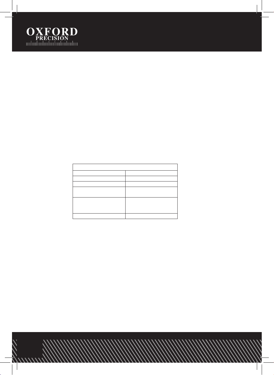
Input Limits
A DC/AC 20A DC/AC (30 seconds
Resistance,
Capacitance, Diode,
SAFETY SYMBOLS
This symbol adjacent to another symbol, terminal or
operating device indicates that the operator must
refer to an explanation in the Operating Instructions
to avoid personal injury or damage to the meter.
This
WARNING
symbol indicates a potentially
hazardous situation, which if not avoided, could
result in death or serious injury.
This
CAUTION
symbol indicates a potentially
hazardous situation, which if not avoided, may
result in damage to the product.
This symbol advises the user that the terminal(s) so
marked must not be connected to a circuit point at
which the voltage with respect to earth ground
exceeds (in this case) 1000 VAC or VDC.
This symbol adjacent to one or more terminals
identifies them as being associated with ranges
that may, in normal use, be subjected to
particularly hazardous voltages. For maximum
safety, the meter and its test leads should not be
handled when these terminals are energized.
CONTROLS AND JACKS
1. Large 2000 count Liquid Crystal Display
With backlight and HOLD, ℃,℉, BAT symbolic signs.
2. Function switch
3. COM (negative) input jack.
—3 — — 4 —
5
POWER
20n
200n
2m
2n
20A
MAX 20A
FUSED
every 15 min.
For 30sec.MAX
A
6
F
9
200m 200
2
TEMP
MAX 200mA
FUSED
mA
20
20
A
F
Ω
V
C
C
!
20
COM
F
V
2M
2
μ
20m
2K
Ω
μ
200
200
20K
200m
V
1000
200
2
20
700
Hz
20K
20M
HOLD
10
11
12
13
F
2
C
20
HOLD
200
XAM °C °F
4
3
2
8
1
7
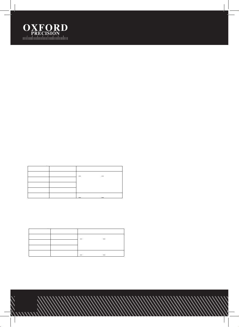
Input Limits
A DC/AC 20A DC/AC (30 seconds
Resistance,
Capacitance, Diode,
SAFETY SYMBOLS
This symbol adjacent to another symbol, terminal or
operating device indicates that the operator must
refer to an explanation in the Operating Instructions
to avoid personal injury or damage to the meter.
This
WARNING
symbol indicates a potentially
hazardous situation, which if not avoided, could
result in death or serious injury.
This
CAUTION
symbol indicates a potentially
hazardous situation, which if not avoided, may
result in damage to the product.
This symbol advises the user that the terminal(s) so
marked must not be connected to a circuit point at
which the voltage with respect to earth ground
exceeds (in this case) 1000 VAC or VDC.
This symbol adjacent to one or more terminals
identifies them as being associated with ranges
that may, in normal use, be subjected to
particularly hazardous voltages. For maximum
safety, the meter and its test leads should not be
handled when these terminals are energized.
CONTROLS AND JACKS
1. Large 2000 count Liquid Crystal Display
With backlight and HOLD, ℃,℉, BAT symbolic signs.
2. Function switch
3. COM (negative) input jack.
5
POWER
20n
200n
2m
2n
20A
MAX 20A
FUSED
every 15 min.
For 30sec.MAX
A
6
F
9
200m 200
2
TEMP
MAX 200mA
FUSED
mA
20
20
A
F
Ω
V
C
C
!
20
COM
F
V
2M
2
μ
20m
2K
Ω
μ
200
200
20K
200m
V
1000
200
2
20
700
Hz
20K
20M
HOLD
10
F
2
C
20
HOLD
200
XAM °C °F
4
3
2
8
1
7
A DC/AC 20A DC/AC (30 seconds
Resistance,
Capacitance, Diode,
SAFETY SYMBOLS
This symbol adjacent to another symbol, terminal or
operating device indicates that the operator must
refer to an explanation in the Operating Instructions
to avoid personal injury or damage to the meter.
This
WARNING
symbol indicates a potentially
hazardous situation, which if not avoided, could
result in death or serious injury.
This
CAUTION
symbol indicates a potentially
hazardous situation, which if not avoided, may
result in damage to the product.
This symbol advises the user that the terminal(s) so
marked must not be connected to a circuit point at
which the voltage with respect to earth ground
exceeds (in this case) 1000 VAC or VDC.
This symbol adjacent to one or more terminals
identifies them as being associated with ranges
that may, in normal use, be subjected to
particularly hazardous voltages. For maximum
safety, the meter and its test leads should not be
handled when these terminals are energized.
CONTROLS AND JACKS
1. Large 2000 count Liquid Crystal Display
With backlight and HOLD, ℃,℉, BAT symbolic signs.
2. Function switch
3. COM (negative) input jack.
—3 — — 4 —
5
POWER
20n
200n
2m
2n
20A
MAX 20A
FUSED
every 15 min.
For 30sec.MAX
A
6
F
9
200m 200
2
TEMP
MAX 200mA
FUSED
mA
20
20
A
F
Ω
V
C
C
!
20
COM
F
V
2M
2
μ
20m
2K
Ω
μ
200
200
20K
200m
V
1000
200
2
20
700
Hz
20K
20M
HOLD
10
11
12
13
F
2
C
20
HOLD
200
XAM °C °F
4
3
2
8
1
7
Input Limits
A DC/AC 20A DC/AC (30 seconds
Resistance,
Capacitance, Diode,
SAFETY SYMBOLS
This symbol adjacent to another symbol, terminal or
operating device indicates that the operator must
refer to an explanation in the Operating Instructions
to avoid personal injury or damage to the meter.
This
WARNING
symbol indicates a potentially
hazardous situation, which if not avoided, could
result in death or serious injury.
This
CAUTION
symbol indicates a potentially
hazardous situation, which if not avoided, may
result in damage to the product.
This symbol advises the user that the terminal(s) so
marked must not be connected to a circuit point at
which the voltage with respect to earth ground
exceeds (in this case) 1000 VAC or VDC.
This symbol adjacent to one or more terminals
identifies them as being associated with ranges
that may, in normal use, be subjected to
particularly hazardous voltages. For maximum
safety, the meter and its test leads should not be
handled when these terminals are energized.
CONTROLS AND JACKS
1. Large 2000 count Liquid Crystal Display
With backlight and HOLD, ℃,℉, BAT symbolic signs.
2. Function switch
3. COM (negative) input jack.
AX
—3 — — 4 —
5
POWER
20n
200n
2m
2n
20A
MAX 20A
FUSED
every 15 min.
For 30sec.MAX
A
6
F
9
200m 200
2
TEMP
MAX 200mA
FUSED
mA
20
20
A
F
Ω
V
C
C
!
20
COM
F
V
2M
2
μ
20m
2K
Ω
μ
200
200
20K
200m
V
1000
200
2
20
700
Hz
20K
20M
HOLD
10
11
12
13
F
2
C
20
HOLD
200
XAM °C °F
4
3
2
8
1
7
Input Limits
A DC/AC 20A DC/AC (30 seconds
Resistance,
Capacitance, Diode,
SAFETY SYMBOLS
This symbol adjacent to another symbol, terminal or
operating device indicates that the operator must
refer to an explanation in the Operating Instructions
to avoid personal injury or damage to the meter.
This
WARNING
symbol indicates a potentially
hazardous situation, which if not avoided, could
result in death or serious injury.
This
CAUTION
symbol indicates a potentially
hazardous situation, which if not avoided, may
result in damage to the product.
This symbol advises the user that the terminal(s) so
marked must not be connected to a circuit point at
which the voltage with respect to earth ground
exceeds (in this case) 1000 VAC or VDC.
This symbol adjacent to one or more terminals
identifies them as being associated with ranges
that may, in normal use, be subjected to
particularly hazardous voltages. For maximum
safety, the meter and its test leads should not be
handled when these terminals are energized.
CONTROLS AND JACKS
1. Large 2000 count Liquid Crystal Display
With backlight and HOLD, ℃,℉, BAT symbolic signs.
2. Function switch
3. COM (negative) input jack.
WARNING
CAUTION