P-Squared SRM User manual

Operations Manual
Last Updated: 11/10/2013
P Squared Ltd

2
Limited Warranty | Copyright © P Squared Ltd 2013
Limited Warranty
Definitions
‘the Company’ means P Squared Ltd and where relevant includes
companies within the same group of companies as P Squared Limited.
‘the Goods’ means the goods or any part thereof supplied by the
Company and where relevant includes: work carried out by the
Company on items supplied by the Purchaser; services supplied by
the Company; and software supplied by the Company.
‘the Purchaser’ means the person or organisation who buys or has
agreed to buy the Goods.
‘the Price’ means the Price of the Goods and any other charges
incurred by the Company in the supply of the Goods.
‘the Contract’ means the quotation, these Conditions of Sale and
any other document incorporated in a contract between the
Company and the Purchaser.
This is the entire Contract between the parties relating to the
subject matter hereof and may not be changed or terminated
except in writing in accordance with the provisions of this Contract.
A reference to the consent, acknowledgment, authority or
agreement of the Company means in writing and only by a director
of the Company.
Warranty and Liability
Important: the purchaser is advised to read this clause
(a) The Company agrees to repair or (at its discretion) replace
Goods which are found to be defective (fair wear and tear
excepted) and which are returned to the Company within
12 months of the date of despatch provided that each of the
following are satisfied:
(i) notification of any defect is given to the Company
immediately upon its becoming apparent to the
Purchaser;
(ii) the Goods have only been operated under normal
operating conditions and have only been subject to
normal use (and in particular the Goods must have been
correctly connected and must not have been subject
to high voltage or to ionising radiation and must not
have been used contrary to the Company’s technical
recommendations);
(iii) the Goods are returned to the Company’s premises at the
Purchaser’s expense;
(iv) any Goods or parts of Goods replaced shall become the
property of
the Company;
(v) no work whatsoever (other than normal and proper
maintenance) has been carried out to the Goods or any
part of the Goods without the Company’s prior written
consent;
(vi) the defect has not arisen from a design made, furnished or
specified by the Purchaser;
(vii) the Goods have been assembled or incorporated into
other goods only in accordance with any instructions
issued by the Company;
(viii) the defect has not arisen from a design modified by the
Purchaser;
(ix) the defect has not arisen from an item manufactured
by a person other than the Company. In respect of any
item manufactured by a person other than the Company,
the Purchaser shall only be entitled to the benefit of any
warranty or guarantee provided by such manufacturer to
the Company.
(b) In respect of computer software supplied by the Company the
Company does not warrant that the use of the software will be
uninterrupted or error free.
(c) The Company accepts liability:
(i) for death or personal injury to the extent that it results
from the negligence of the Company, its employees
(whilst in the course of their employment) or its agents (in
the course of the agency);
(ii) for any breach by the Company of any statutory
undertaking as to title, quiet possession and freedom from
encumbrance.
(d) Subject to conditions (a) and (c) from the time of despatch of
the Goods from the Company’s premises the Purchaser shall
be responsible for any defect in the Goods or loss, damage,
nuisance or interference whatsoever consequential economic
or otherwise or wastage of material resulting from or caused by
or to the Goods. In particular the Company shall not be liable
for any loss of profits or other economic losses. The Company
accordingly excludes all liability for the same.
(e) At the request and expense of the Purchaser the Company will
test the Goods to ascertain performance levels and provide a
report of the results of that test. The report will be accurate at
the time of the test, to the best of the belief and knowledge of
the Company, and the Company accepts no liability in respect
of its accuracy beyond that set out in Condition (a).
(f ) Subject to Condition (e) no representation, condition, warranty
or other term, express or implied (by statute or otherwise) is
given by the Company that the Goods are of any particular
quality or standard or will enable the Purchaser to attain any
particular performance or result, or will be suitable for any
particular purpose or use under specific conditions or will
provide any particular capacity, notwithstanding that the
requirement for such performance, result or capacity or that
such particular purpose or conditions may have been known
(or ought to have been known) to the Company, its employees
or agents.
(g) (i) To the extent that the Company is held legally liable to
the Purchaser for any single breach of contract, tort,
representation or other act or default, the Company’s
liability for the same shall not exceed the Price of the
Goods.
(ii) The restriction of liability in Condition (g)(i) shall not apply
to any liability accepted by the Seller in Condition (c).
(h) Where the Goods are sold under a consumer transaction
(as defined by the Consumer Transactions (Restrictions on
Statements) Order 1976) the statutory rights of the Purchaser
are not affected by these Conditions of Sale.
Warranty Returns
Please contact P Squared to obtain a returns authorisation prior to returning any
goods for warranty repair.
Returns Contact:
Returns
P Squared Ltd
1-2 Maritime House
Livingstone Road
Hessle
East Riding Of Yorkshire
HU13 0EG
Telephone: +44 1482 350700
Fax: +44 1482 350701
Email: [email protected]
Web: www.psquared.net
This Warranty Does Not Affect Your Statutory
Rights
If you need to return goods to P Squared Ltd, for whatever reason,
please contact P Squared Ltd beforehand to receive a returns reference number.

SRM Operations Manual
3
Table of Contents | Copyright © P Squared Ltd 2013
Table of Contents
Contents
Table of Contents....................................................................................................................................3
Introduction ............................................................................................................................................5
Layout & Dimensions ..............................................................................................................................6
Channel Overview................................................................................................................................8
Microphone / Line Channels (Channels 1-4)...........................................................................................9
Channel Layout & Function.................................................................................................................9
Rear Panel Layout & Function...........................................................................................................11
Myriad / Line Channels (Channels 5-8).................................................................................................12
Channel Layout & Function...............................................................................................................12
Rear Panel Layout & Function...........................................................................................................14
Telephone / AUX Channel (Channel 9) .................................................................................................15
Channel Layout & Function...............................................................................................................15
Rear Panel Layout & Function...........................................................................................................17
Monitor Section ....................................................................................................................................18
Layout & Function.............................................................................................................................18
Rear Panel Layout & Function...........................................................................................................21
Setting Up The Myriad Intelligent Interface (MII).................................................................................23
What Is MII?......................................................................................................................................23
Start Button Colour Status Key .........................................................................................................23
Starting & Stopping Playback In Myriad From The SRM...................................................................24
Preview Cart Player Mode ................................................................................................................24
Virtual Mic Live Light.........................................................................................................................24
Setting Up The Myriad Intelligent Interface .....................................................................................25
Trouble Shooting MII ........................................................................................................................30
Myriad Reports ‘Invalid Port Number’ On Start-up ......................................................................31
Using The Telephone Interface.............................................................................................................31
What You Will Need..........................................................................................................................31
Connecting The Telephone Equipment To The SRM ........................................................................32
Using The Telephone Interface.........................................................................................................33
Procedure For Making A Call And Routing It Through The Mixing Desk.......................................34
Recording A Telephone Call While You Are ‘On Air’, For Broadcasting Later...............................36

4
Table of Contents | Copyright © P Squared Ltd 2013
Trouble Shooting...............................................................................................................................38
Reducing Noise Using The R-BAL and C-BAL Adjustments ...........................................................38
SRM Setup Mode ..................................................................................................................................39
Restore Factory Defaults...................................................................................................................40
Change LED Meter Between PPM & VU Modes ...............................................................................40
Switching On 48v Phantom Power On/Off Microphone Channels...................................................41
Other Channel Configuration –Advanced Settings ..........................................................................45
Switching To Setup Mode .............................................................................................................45
Selecting The Settings Page You Want To Work With ..................................................................46
Available Settings..........................................................................................................................48
Settings Page 1 - Input Select Modes............................................................................................48
Settings Page 2 - PGM & REC Button Modes (available on all channels) .....................................49
Settings Page 3 - PFL Modes (available on all channels)...............................................................49
Settings Page 4 –Remote Modes .................................................................................................50
Saving Settings And Existing Setup Mode.....................................................................................51
Technical Specifications........................................................................................................................52
Notes:....................................................................................................................................................58
P Squared Contact Details.....................................................................................................................59
SRM Operations Manual
5
Introduction | Copyright © P Squared Ltd 2013
Introduction
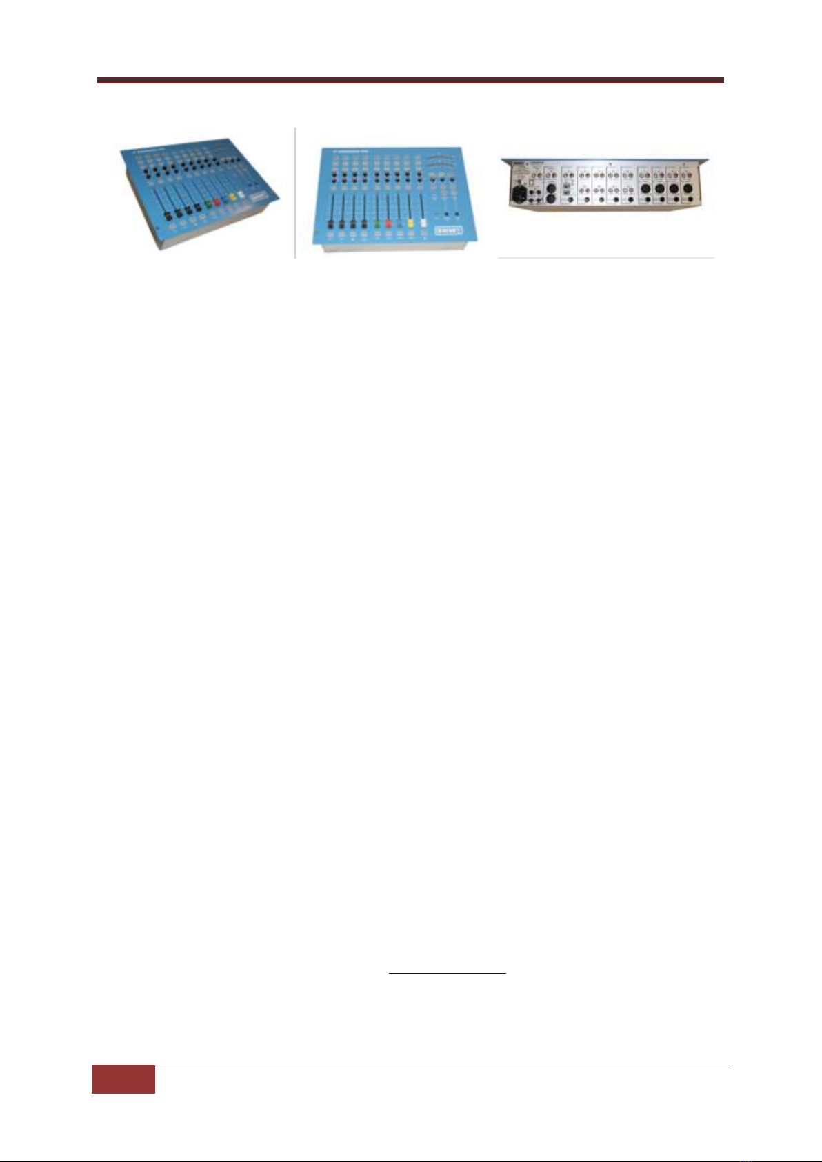
The SRM is a small, fixed format broadcast audio mixer designed to provide a versatile and robust
mixing solution for small and medium scale radio stations.
We set out to design a mixer that would combine key broadcast radio features with a layout that
would appeal to novice and broadcast professionals alike. The result is a mixer that includes many
features we felt were lacking in the alternatives but still retains simplicity and clarity to the end user.
The SRM was also designed to work with the Myriad radio playout software. The Myriad Intelligent
Interface provides a consistent data link between the SRM mixer and your Myriad playout system
providing un-paralleled levels of interactivity between the two systems and blurring the lines
between software and broadcast hardware.
The SRM is a fixed format, nine channel broadcast mixer boasting the following key features:
User friendly broadcast mixer
Clear, simple layout with no jargon
Designed for school & community radio
Nine multi-function channel mixer
Built in telephone interface
Built in headphone volume limiter
Large, simple LED volume display
Remote output for fader starts
Speaker muting when ‘Mics’ are on
External mic-light switching output
‘Program’ and ‘record’ outputs
‘Aux’ input for iPod or MP3 players
Four microphone/line channels
Four Myriad channels
Switchable telephone/AUX channel
Connects to Myriad via USB cable
Start buttons for Myriad Cart Players
Channel lights show Myriad Cart status
Rack or flush mountable
Guest headphone ‘talkback’
Reliable, low cost mixing solution
For more detail on The SRM mixer, please visit www.thesrm.co.uk

6
Layout & Dimensions | Copyright © P Squared Ltd 2013
Layout & Dimensions
Dimensions
Width: 482.6mm
Height: 355.0mm
Depth: 107mm

SRM Operations Manual
7
Layout & Dimensions | Copyright © P Squared Ltd 2013

8
Channel Overview | Copyright © P Squared Ltd 2013
Channel Overview
4 x Mic / Line Channels
Selectable microphone or stereo line inputs.
Phantom power (48v) optionally available in ‘mic’ mode.
Hardware output available for ‘remote start’ when in ‘line’ mode.
Selectable PGM and REC outputs.
4 x Myriad / Line Channels
Selectable Myriad or stereo line inputs.
When in Myriad mode, channel status is controlled by Myriad via USB connection. Start buttons also
control Cart Players in Myriad.
Hardware output available in ‘Line’ mode for remotely starting external devices.
Selectable PGM or REC outputs for flexibility.
1 x Telephone / AUX Channel
Select between telephone interface mode and stereo ‘AUX’ inputs.
When in telephone, you can connect an analogue telephone line to the SRM to allow you to make
and receive phone calls through the mixing desk (standard handset required).
The ‘AUX’ stereo input provides a convenient additional input for external devices such as MP3
players.
Monitoring & Headphones
The built in LED volume meters can be set to display output in PPM (default) or VU modes which are
selectable via the SRM Setup Mode. The LED meters can be switched to display volume for either
PGM (Program Output Bus), REC (Record Output Bus) or Broadcast Listen (external input used for
‘off air’ monitoring).
The SRM includes built in headphone limiting to limit the maximum volume for presenter and guest
headphones. Guest headphone ‘talkback’ is also provided to allow the presenter to talk via the guest
headphones using Microphone Channel 1.
The Monitor volume control is used to control the speaker volume level in the studio.

SRM Operations Manual
9
Microphone / Line Channels (Channels 1-4) | Copyright © P Squared Ltd 2013
Microphone / Line Channels (Channels 1-4)
Channel Layout & Function
Channel Layout
Description
1 - Mic / Line Button: This button allows you to switch the channel
between the Microphone input and the stereo line level inputs (see rear of
the channel below). In addition, when in Mic mode, raising the channel
fader will operate the Light Control logic which can be connected to an
external ‘Mic Live’ light. When in Line mode, raising the fader will send a
signal out from the Remote Output (see rear of panel) for starting remote
devices such as CD players.
Button is illuminated when in Line Mode. Please note that this button can
be disabled using the SRM Setup Mode.
2 –PGM Button (Program Bus) –This button allows you to select whether
the output of the channel should be mixed into the Program Bus Output.
The Program Bus Output is the main mixing desk output which would
normally be connected to your transmission or encoding system. The
reason for this function is to allow you to de-select channels to be included
in main Program Bus Output but still use the channels (for recording etc).
Button illuminates when selected.
3 –REC Button (Record Bus) –This button allows you to select whether the
output from the channel should be mixed to the Record Bus Output which
would normally be connected to your Myriad system (or other playout
system). This function allows you to select which channels Myriad should
record, which is very useful when, voice tracking or recording telephone
calls (when live on air etc). Button illuminates when selected.
4 - Trim: The Trim control allows you to adjust the overall volume level for
the channel when the fader is in the upmost position. Basically, this allows
you to set how loud the channel should be when the fader is fully up. This is
very useful for setting relative levels between channels with different
source volumes.
5 - PAN / BAL (Balance): This control has two functions depending on
whether you are in Mic or Line mode. In Mic mode the control acts as a
PAN control which allows you to set the input bias for the channel to either
be left channel input or right channel input. In PAN mode, if you rotate the
knob all the way to the left then the right channel input will effectively
turned off.
The control switches to BAL (balance) mode when Line is selected which
does the same thing (i.e. allows you to alter the left / right bias) but turning
the know fully to the left will still allow some of the right hand channel to
be heard, it will not mute it fully as in PAN mode.
6 - Pre Fade: The button allows you to select the Pre-Fade mode for the
channel. The Pre-Fade mode allows you to listen to the channel without it
actually being sent to the PGM or REC outputs (see above) which is
essential if you want to check something prior to it going ‘on-air). To use
this feature, first pull the fader right down (otherwise it will be broadcast
anyway), then press the Pre-Fade button. You will now be able to hear
10
Microphone / Line Channels (Channels 1-4) | Copyright © P Squared Ltd 2013
anything playing through your headphones (providing the Auto-Prefade
option in the monitor section is set –see Monitor Section) but it will not be
heard ‘on-air’.
This is an essential tool for radio. Let’s say you have a guest in the studio.
You need to check that their mic levels are ok and adjust the Trim on their
mic channel if they are too quiet or too loud. Simply pull down their mic
fader, press the Pre-Fade button and ask them to speak into the mic. You
will be able to hear them through your headphones but crucially you can
also see their ‘mic levels’ on the LED Meter (bar graph) so you can adjust
the channel Trim accordingly. Once you are happy, de-select the Pre-Fade
button and don’t forget to put their fader up when you want them to be
able to speak.
7 - Fader: The Fader is a linear volume control for the channel. By moving
the fader up or down, you will alter the volume of the audio source the
channel is connected to.
8 - Start Button: This button is only operational when in Line mode and it is
used to send a start signal to compatible external devices (such as some CD
players) via the Remote Start Output (see rear of channel).

SRM Operations Manual
11
Microphone / Line Channels (Channels 1-4) | Copyright © P Squared Ltd 2013
Rear Panel Layout & Function
Channel Layout
Description
1 - Line Input: This RCA ( phono) input allows you to plug in a stereo
source that will be used by the channel when in Line mode. The source
should be domestic level (unbalanced) as found on most CD players and
hi-fi equipment. If you need to plug in a balanced source then you
should consult support@psquared.net for more information.
2 - Mic Trim: This small screw adjuster allows you to alter the base
amplification level for microphones plugged into the channel. This is in
addition to the Trim control on the channel itself. This control should
only be adjusted by a competent audio engineer.
3 - Mic Input –This XLR input is used to plug in a standard microphone
cable. The SRM can support both dynamic (un-powered) and condenser
(powered using 48v phantom power) microphones but you will need to
activate the phantom power option when using a condenser
microphone (see SRM Setup Mode for more detail).
4 - Remote Output: This output is only used when the channel is
switched to Line mode and it is used to send a ‘start’ signal to
compatible external devices such as some CD players. This Remote
Output is effectively a closing contact between the tip of the ¼” jack
and the sleeve.

12
Myriad / Line Channels (Channels 5-8) | Copyright © P Squared Ltd 2013
Myriad / Line Channels (Channels 5-8)
Channel Layout & Function
Channel Layout
Description
1 - MYR / Line Button: This button allows you to switch the channel
between the Myriad input and the stereo line level inputs (see rear of the
channel below). In addition, when in MYR (Myriad) mode, the channel will
also interact with a correctly configured Myriad playout system via the
Myriad Intelligent Interface (USB) connection. This will alter the Start
button functionality to allow you to Play / Pause the corresponding Cart
Player in Myriad. The status of the Cart Player in Myriad will also be
displayed as colour changes on the Start button.
Button is illuminated when in Line Mode. Please note that this button can
be disabled using the SRM Setup Mode.
2 –PGM Button (Program Bus) –This button allows you to select whether
the output of the channel should be mixed into the Program Bus Output.
The Program Bus Output is the main mixing desk output which would
normally be connected to your transmission or encoding system. The
reason for this function is to allow you to de-select channels to be included
in main Program Bus Output but still use the channels (for recording etc).
Button illuminates when selected.
3 –REC Button (Record Bus) –This button allows you to select whether the
output from the channel should be mixed to the Record Bus Output which
would normally be connected to your Myriad system (or other playout
system). This function allows you to select which channels Myriad should
record, which is very useful when, voice tracking or recording telephone
calls (when live on air etc). Button illuminates when selected.
4 - Trim: The Trim control allows you to adjust the overall volume level for
the channel when the fader is in the upmost position. Basically, this allows
you to set how loud the channel should be when the fader is fully up. This is
very useful for setting relative levels between channels with different
source volumes.
5 - BAL (Balance): This control allows you to alter the bias for the channel
between the left and right inputs. When central, both left and right inputs
will be equal but turning the knob to either the left or the right will alter the
bias for the channel in favour of the selected direction.
6 - Pre Fade: The button allows you to select the Pre-Fade mode for the
channel. The Pre-Fade mode allows you to listen to the channel without it
actually being sent to the PGM or REC outputs (see above) which is
essential if you want to check something prior to it going ‘on-air). To use
this feature, first pull the fader right down (otherwise it will be broadcast
anyway), then press the Pre-Fade button. You will now be able to hear
anything playing through your headphones (providing the Auto-Prefade
option in the monitor section is set –see Monitor Section) but it will not be
heard ‘on-air’.
This is an essential tool for radio. Let’s say you have a guest in the studio.
You need to check that their mic levels are ok and adjust the Trim on their

SRM Operations Manual
13
Myriad / Line Channels (Channels 5-8) | Copyright © P Squared Ltd 2013
mic channel if they are too quiet or too loud. Simply pull down their mic
fader, press the Pre-Fade button and ask them to speak into the mic. You
will be able to hear them through your headphones but crucially you can
also see their ‘mic levels’ on the LED Meter (bar graph) so you can adjust
the channel Trim accordingly. Once you are happy, de-select the Pre-Fade
button and don’t forget to put their fader up when you want them to be
able to speak.
7 - Fader: The Fader is a linear volume control for the channel. By moving
the fader up or down, you will alter the volume of the audio source the
channel is connected to. When in MYR mode, the corresponding Cart Player
will be switched to ‘Preview’ mode when the fader is fully closed (down
position).
8 - Start Button: This button has different functions depending on whether
you are in Line or MYR modes.
When in Line mode it is used to send a start signal to compatible external
devices (such as some CD players) via the Remote Start Output (see rear of
channel).
When in Myriad mode, it is used to control the corresponding Cart Player in
Myriad and also to display the status of the Cart Player by changing the
colour and illumination state. The following list outlines the possible states
for the Start button when in Myriad mode:
Not illuminated –The corresponding Cart Player in Myriad is empty.
Solid Red –Cart is cued in Cart Player (or paused) and is ready to
start playback.
Solid Green –Cart is playing in Cart Player.
Flashing Orange –Cart has reached the final 10 seconds of playback
(before Extro point).
Flashing Red –Cart has reached final 5 seconds of playback (before
extro point).
Solid Orange –Cart has reached extro point but is still in Cart
Player.
Please note that pressing the Start button will have the following effects:
Press Start When Cart Is Cued / Paused (solid orange) –This will
start playback of the Cart Player in Myriad.
Press Start When Cart Is Playing (solid green) –This will pause the
Cart Player in Myriad.
You will also see that if the Fader is closed then the corresponding Cart
Player in Myriad will switch to ‘Preview’ mode.

14
Myriad / Line Channels (Channels 5-8) | Copyright © P Squared Ltd 2013
Rear Panel Layout & Function
Channel Layout
Description
1 - Myriad Input: This RCA (phono) input allows you to plug in to the
corresponding soundcard output on your Myriad playout system. So If
Cart Player 1 is configured to use soundcard outputs 1&2 then these
are the outputs that should be plugged into Myriad Channel 1 Inputs.
2 x Line Input: This RCA (phono) input allows you to plug in a stereo
source that will be used by the channel when in Line mode. The source
should be domestic level (unbalanced) as found on most CD players
and hi-fi equipment. If you need to plug in a balanced source then you
should consult support@psquared.net for more information.
Remote Output: This output is only used when the channel is switched
to Line mode and it is used to send a ‘start’ signal to compatible
external devices such as some CD players. This Remote Output is
effectively a closing contact between the tip of the ¼” jack and the
sleeve.

SRM Operations Manual
15
Telephone / AUX Channel (Channel 9) | Copyright © P Squared Ltd 2013
Telephone / AUX Channel (Channel 9)
Channel Layout & Function
Channel Layout
Description
1 - TEL / AUX: This button allows you to switch the channel between TEL
(Telephone) mode and AUX input mode. When TEL mode is selected, the
channel switches to Telephone mode and enables the built in telephone
interface (see rear of panel). The function of several buttons is also altered
when in Telephone mode.
When in AUX mode, the channel uses the stereo input from either the AUX
input on the rear of the mixer or the small AUX jack input located on the
mix face in the Monitoring section.
Button is illuminated when in AUX Mode. Please note that this button can
be disabled using the SRM Setup Mode.
2 - PGM Button (Program Bus) –This button allows you to select whether
the output of the channel should be mixed into the Program Bus Output.
The Program Bus Output is the main mixing desk output which would
normally be connected to your transmission or encoding system. The
reason for this function is to allow you to de-select channels to be included
in main Program Bus Output but still use the channels (for recording etc).
Button illuminates when selected.
3 –REC Button (Record Bus) –This button allows you to select whether the
output from the channel should be mixed into the Record Bus Output
which would normally be connected to your Myriad system (or other
playout system). This function allows you to select which channels Myriad
should record, which is very useful when, voice tracking or recording
telephone calls (when live on air etc). Button illuminates when selected.
4 - Trim: The Trim control allows you to adjust the overall volume level for
the channel when the fader is in the upmost position. Basically, this allows
you to set how loud the channel should be when the fader is fully up. This is
very useful for setting relative levels between channels with different
source volumes.
5 - PAN / BAL (Balance): This control has two functions depending on
whether you are in TEL or AUX mode. In TEL mode the control acts as a PAN
control which allows you to set the input bias for the channel to either be
left channel or right channel. In PAN mode, if you rotate the knob all the
way to the left then the right channel input will effectively turned off.
The control switches to BAL (balance) mode when AUX is selected which
does the same thing (i.e. allows you to alter the left / right bias) but turning
the knob fully to the left will still allow some of the right hand channel to be
heard, it will not mute it fully as in PAN mode.

16
Telephone / AUX Channel (Channel 9) | Copyright © P Squared Ltd 2013
6 - Pre Fade & TB: The button allows you to select the Pre-Fade mode for
the channel. The Pre-Fade mode allows you to listen to the channel without
it actually being sent to the PGM or REC outputs (see above), which is
essential if you want to check something prior to it going ‘on-air). To use
this feature, first pull the fader right down (otherwise it will be broadcast
anyway), then press the Pre-Fade button. You will now be able to hear
anything playing through your headphones (providing the Auto-Prefade
option in the monitor section is set –see Monitor Section) but it will not be
heard ‘on-air’.
When the fader is switched to Tel mode, the Pre-Fade option also enables
Talk Back (TB) to the caller on the telephone. This special feature allows you
to talk to your caller using Microphone Channel 1 without having to open
the Microphone 1 fader.
So once you have a caller, you can use the Pre-Fade & TB button to listen to
them and talk to them prior to opening their fader and putting them on air.
Caution: Remember when you push this button, they can hear you also
through the main presenter mic so be careful what you say!
7 - Fader: The Fader is a linear volume control for the channel. By moving
the fader up or down, you will alter the volume of the audio source the
channel is connected to.
8 - Line Hold: This button is only operational when in TEL mode and it is
used to connect and disconnect the telephone line via the mixing desk.
Think of this as pickup or putting down the receiver in a traditional phone.
Please note that the button will flash when a phone call is received and will
illuminate when the desk is connected to the call. See section on Telephone
Interface for more detailed operation.

SRM Operations Manual
17
Telephone / AUX Channel (Channel 9) | Copyright © P Squared Ltd 2013
Rear Panel Layout & Function
Channel Layout
Description
1 - Aux Input: This RCA (phono) input allows you to plug in a stereo source
that will be used by the channel when in AUX mode. The source should be
domestic level (unbalanced) as found on most CD players and hi-fi
equipment. If you need to plug in a balanced source then you should
consult support@psquared.net for more information.
Please note that there is a small jack AUX input on the Monitor Section of
the mixer face. These two inputs are effectively the same.
2 - R-BAL (Resistor) & C-BAL (Capacitor): These small screw adjuster are
for adjusting the signal levels on the telephone interface. These are
factory set against a standard BT line and should not need adjusting under
normal circumstances.
3 - Line (phone) –This allows you to connect the SRM to a standard BT
analogue phone line. You will need an RJ11 (male) to BT (male) cable to
connect from your BT phone socket to the SRM.
Please note that you will need a true analogue phone line socket similar to
one you would need for a standard fax machine. If you have a digital
phone exchange, you will need to talk to your supplier about analogue
phone socket provision.
4 - Handset: This is used to connect a standard analogue telephone
handset to the SRM to allow you to dial outgoing calls which can then be
transferred to the mixer for use ‘on air’.
You will need an RJ11 (male) to RJ11 (male) cable to connect to most
handsets.
5 - Remote Output: This output is only used when the channel is switched
to AUX mode and it is used to send a ‘start’ signal to compatible external
devices such as some CD players. This Remote Output is effectively a
closing contact between the tip of the ¼” jack and the sleeve.
18
Monitor Section | Copyright © P Squared Ltd 2013
Monitor Section
Layout & Function
Channel Layout
Description
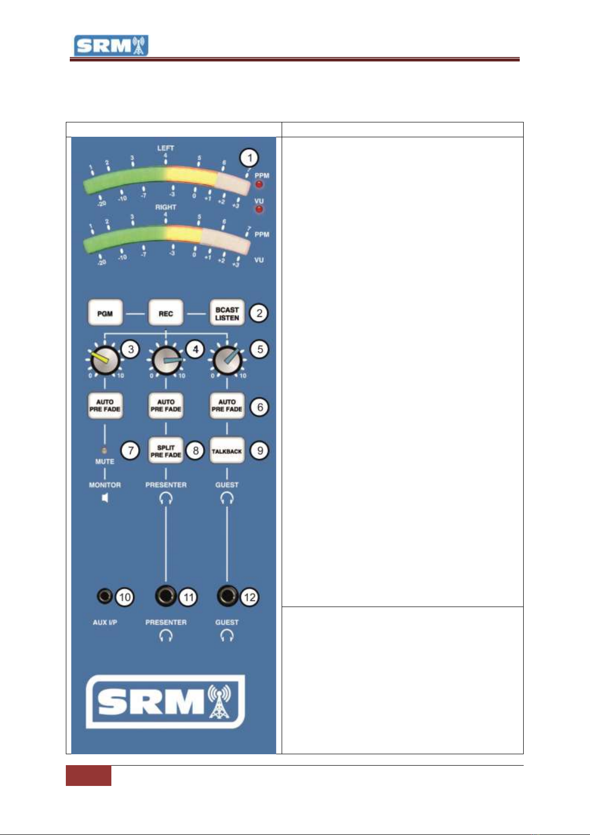
1 - LED Meter Lights: The LED Meter Lights provide
a visual representation of the audio levels passing
through the selected SRM output bus. The LED’s are
colour coded so you can see quickly when things
are too loud:
Green –Level ok (target for music)
Yellow –Level still ok but getting louder
(target for speech)
Red –Level too high and likely to lead to
distortion
The LED Meters can be switched to display in PPM
or VU modes (see SRM Setup Mode) with PPM set
as the default. In PPM mode, the display shows an
average volume of a short time period so the
display is more consistent and easier to work with.
In VU mode the display shows all volume peaks and
so is more accurate but also more erratic. We
recommend sticking with PPM mode.
The LED Meter section can be set to display the
current volume for any of the following:
PGM –The LED shows the volume for the
Program Output Bus (main desk output)
REC –The LED shows the volume for the
REC Output Bus
BCAST LISTEN (Broadcast Listen) –The LED
shows the volume for the Broadcast Listen
input which is commonly used to monitor a
‘post process’ or ‘off air’ source to ensure
what you are playing is actually being
broadcast.
Pre-Fade –When you activate the Pre-Fade
mode on any channel, the LED display
switches to showing the volume for all Pre-
Fade enabled channels.
2 - PGM / REC / BCAST LISTEN Butons: These
buttons are used to select the output bus that you
want the LED Meter to display (see above) plus is
sent to the studio MONITORS (speakers) and
PRESENTER & GUEST HEADPHONE. To switch to
PGR, REC or BCAST Listen, just press the button. The
bus that the LED Meter is currently displaying is
indicated by the button being illuminated. One of
these options will be selected at all times.
Please note that when you press a Pre-Fade button

SRM Operations Manual
19
Monitor Section | Copyright © P Squared Ltd 2013
on any channel, the LED Display switches
automatically to display the volume on all channels
that have Pre-Fade selected.
3 - Studio Speaker Volume: This is the left hand
volume knob (with the yellow top - follow the line
down from the knob and you will see a speaker
icon).
Use this knob to adjust the volume of your studio
speakers.
4 - Presenter Headphone Volume: The middle
volume knob (blue top) is used to control the
volume of the main presenters headphones.
Please note that the SRM has an adjustable
headphone limiter which prevents the volume of
the headphones from going too high. Once the
volume limit has been reached, turning the
headphones higher will result in distortion but no
additional volume.
5 - Guest Headphone Volume: The right hand
volume knob (blue top) is used to control the
volume of the guest headphones.
Please note that the SRM has an adjustable
headphone limiter which prevents the volume of
the headphones from going too high. Once the
volume limit has been reached, turning the
headphones higher will result in distortion but no
additional volume.
6 - Auto Pre-Fade Buttons: There are Auto Pre-Fade
button for the Speakers, Presenter Headphones and
Guest Headphones and they are used to select
whether Speakers / Presenter Headphone / Guest
Headphones will automatically switch to listening to
Pre-Fade channels when one or more channels have
Pre-Fade selected.
As outlined in the Pre-Fade sections on the
channels, pressing the Pre-Fade button on a
channel allows you to listen to the audio on the
channel without having the Fader up. This allows
you to preview items and to check audio levels.
The Auto Pre-Fade buttons allows you to select who
will hear the Pre-Fade once activated.
Speaker –The studio speakers will
automatically switch to playing Pre-Fade

20
Monitor Section | Copyright © P Squared Ltd 2013
once activated.
Presenter –The presenter’s headphones
will automatically switch to playing Pre-
Fade once activated.
Guest’s – The guest’s headphones will
automatically switch to playing Pre-Fade
once activated.
You can have any or all of these options activated.
Selected options are illuminated.
7 - Mute: The Mute light switches on when a
Microphone Channel fader is opened and indicates
that the volume to the studio speakers has been cut
to prevent feedback. This can also be reflected by
an external ‘Mic Live’ light connected to the Light
Controller output on the rear panel.
8 - Split Pre-Fade: This option allows you to set the
SRM to play Pre-Fade audio to the left side of the
presenters headphones and PGM / REC / BCAST
Listen (whichever is selected) to the right hand side
of the headphones. This is useful if you need to
preview something but also want to keep an ear on
what is being broadcast.
9 - Talkback: The Talkback button allows you ‘talk’
to the Guest Presenter via their headphones. If you
hold down this button and then talk into the
microphone plugged into Microphone Channel 1
(with the fader down of course) then your voice will
be mixed into whatever the Guest Headphones are
listening to. This is great if your guest is located
away from you or if you just want to warn them the
song is coming to an end.
10 - AUX I/P (AUX Input): This mini-jack input
allows you to easily plug in external devices such as
iPods and phones etc.
To access this input you will need to switch the TEL
/ AUX channel (channel 9) to AUX mode.
Please note that there is also an AUX Input on the
rear panel but it is just a parallel of this input.
11 –Presenter Headphones: Allows you to plug in
your main presenter headphones.
Please note that this connector is also available on
the rear panel.
12 –Guest Headphones: Allows you to plug in your
main presenter headphones.
Please note that this connector is also available on
the rear panel.
Table of contents


