P1PE P4000i User manual

FOR YOUR SAFETY
You must read and understand
this manual before use.
Keep this manual for future
reference.

2
DISCLAIMERS:
All information, illustrations and specifications in this manual are based on the latest information available at
the time of publishing. The illustrations used in this manual are intended as representative reference views only.
Moreover, because of our continuous product improvement policy, we may modify information, illustrations and/or
specifications to explain and/or exemplify a product, service or maintenance improvement. We reserve the right
to make any change at any time without notice. Some images may vary depending upon which model is shown.
DANGER
This manual contains important instructions for operating this generator. For your safety and the safety of others, be sure
to read this manual thoroughly before operating the generator. Failure to properly follow all instructions and precautions
can cause you and others to be seriously hurt or killed.
SAFETY..................................................................................................3
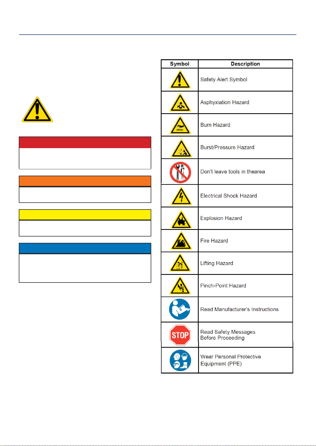
Safety Definitions.................................................................... 3
Safety Symbol Definitions....................................................... 3
General Safety Rules...............................................................4
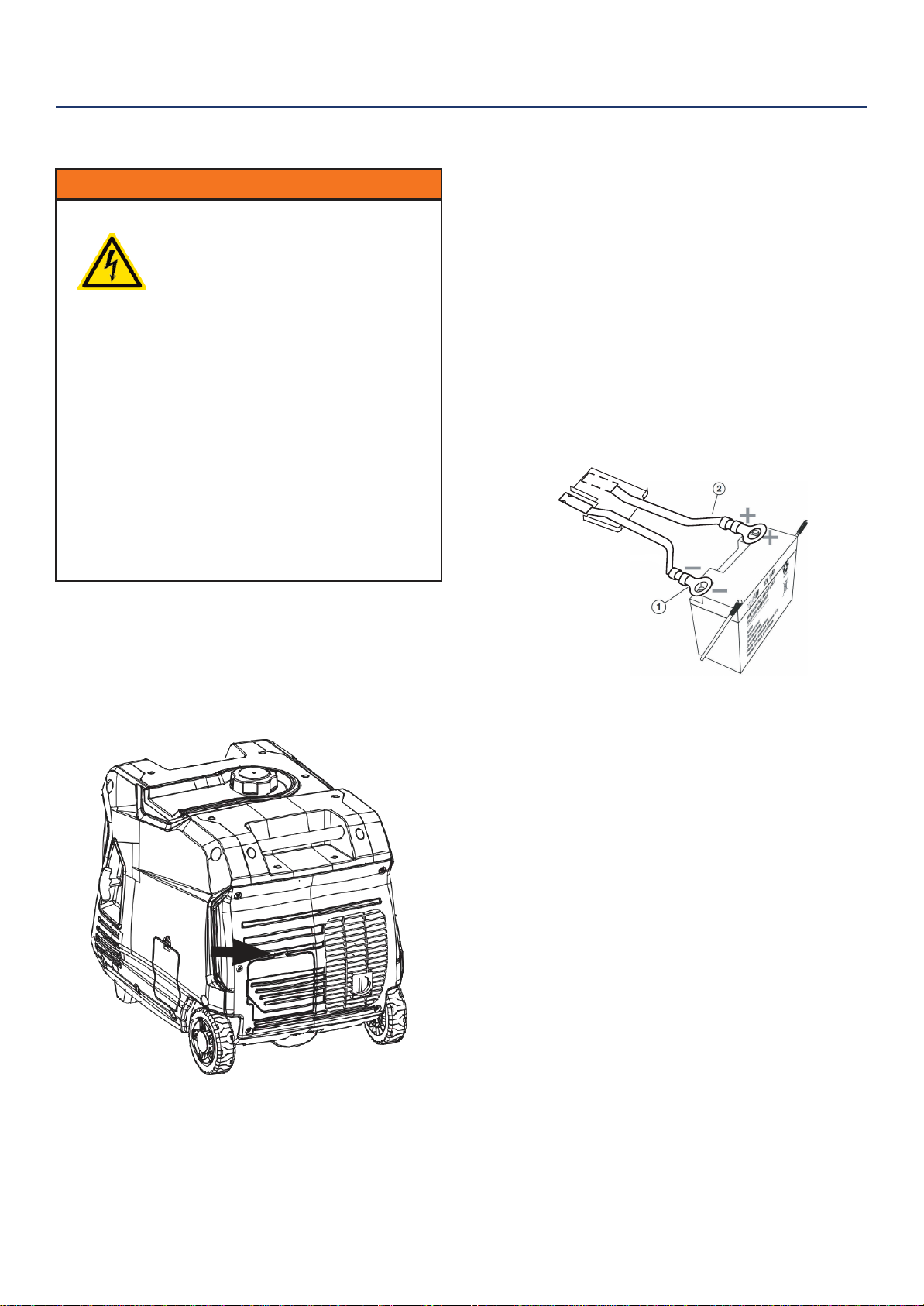
ASSEMBLY.............................................................................5
Hooking Up the Battery.............................................................5
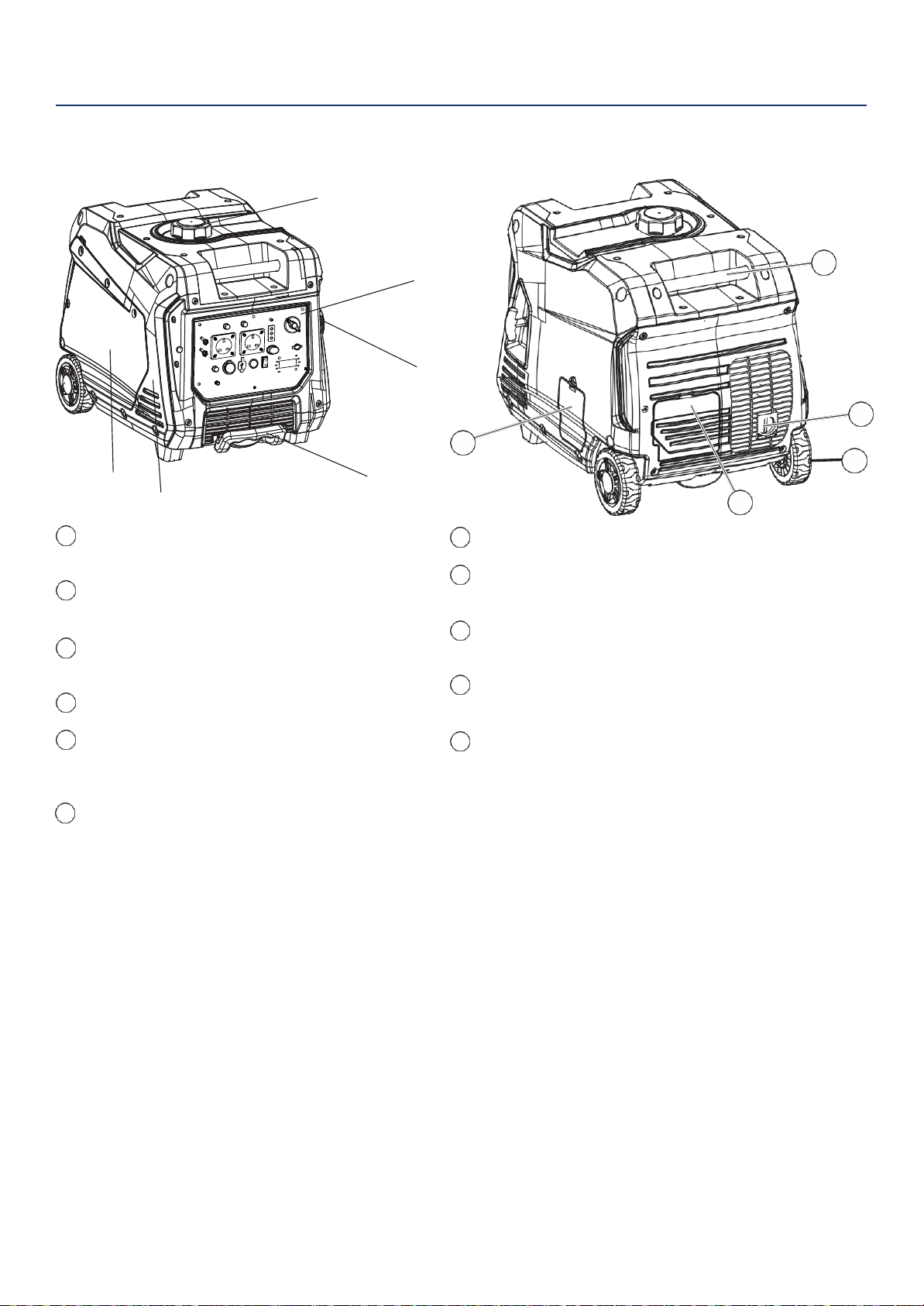
FEATURES..............................................................................6
Basic Inverter Features.............................................................6
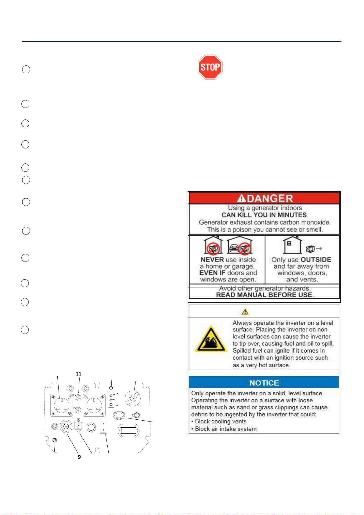
Control Panel Features............................................................ 7
OPERATION.............................................................................8
Before Starting the Inverter.......................................................8
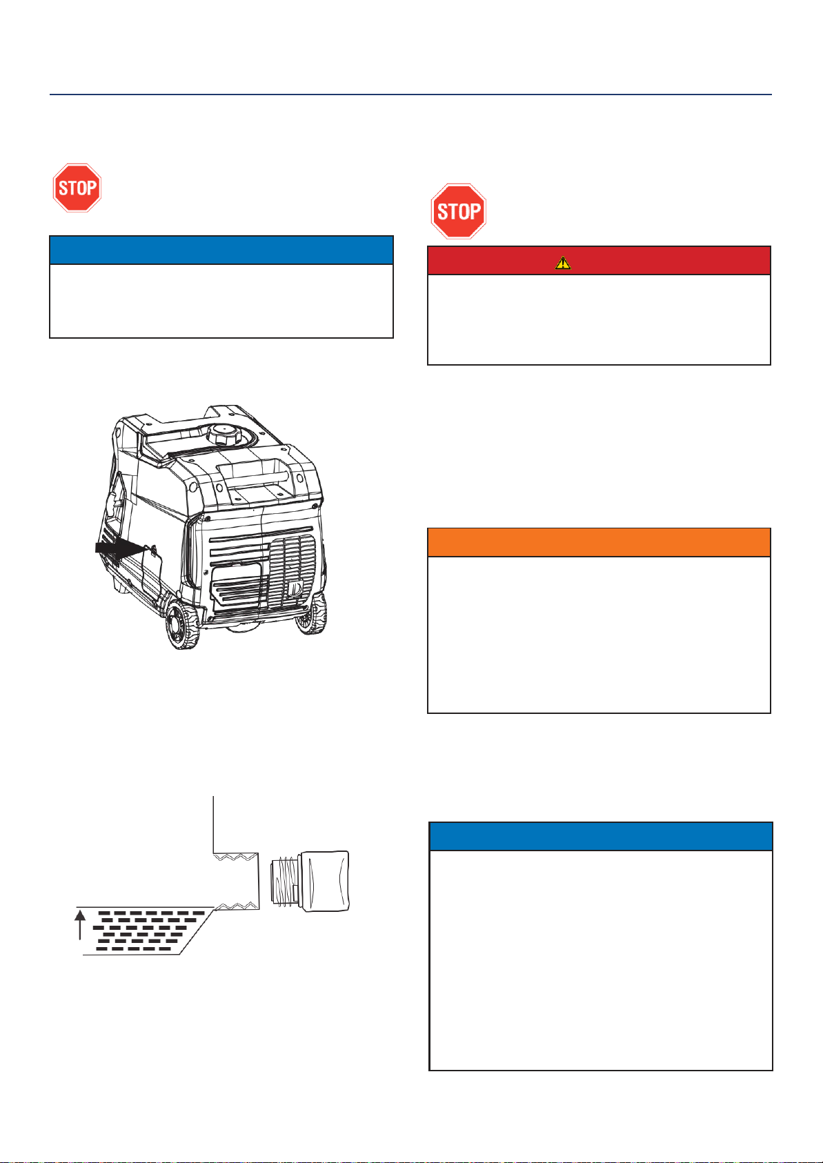
Location Selection.....................................................................8
Weather ....................................................................................8
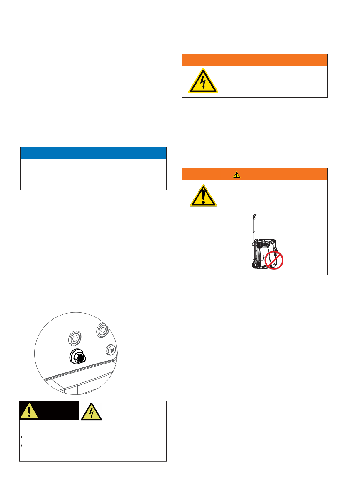
Grounding the Inverter.............................................................. 8
High Altitude Operation..............................................................8
Power Cord............................................................................... 9
Inverter Paralleling Operation ................................................... 9
Initial Oil Fill..............................................................................10
Adding/Checking Engine Fluids and Fuel.................................10
Checking and/or Adding Engine Oil ..........................................10
Adding Petrol to the Fuel Tank..................................................11
Starting the Inverter...................................................................12
Electric Start..............................................................................12
Manual Start..............................................................................12
Wireless Remote Start...............................................................12
Stopping the Inverter.................................................................13
Using Efficiency Mode...............................................................13
Resetting the Reset Breaker.....................................................13
MAINTENANCE........................................................................14
Maintenance Schedule ............................................................14
Engine Oil Maintenance...........................................................15
Checking Engine Oil ................................................................15
Adding Engine Oil .................................................................... 15
Changing Engine Oil.................................................................16
Air Filter Maintenance...............................................................16
Cleaning the Air Filter...............................................................16
Draining the Float Bowl.............................................................17
Spark Plug Maintenance...........................................................17
Cleaning the Spark Arrestor......................................................18
Checking and Adjusting Valve Lash..........................................18
Cleaning the Inverter.................................................................19
Battery Service..........................................................................19
Storage .....................................................................................20
TROUBLESHOOTING...............................................................21
Recycling & Product Disposal...................................................22
Declaration of Conformity..........................................................23
Contact Details..........................................................................24

3
SAFETY
SAFETY DEFINITIONS
The words DANGER, WARNING, CAUTION and
NOTICE are used throughout this manual to highlight
important information. Be certain that the meanings of
these alerts are known to all who work on or near the
equipment.
SAFETY SYMBOL DEFINITIONS
This safety alert symbol appears
with most safety statements. It
means attention, become alert, your
safety is involved! Please read and
abide by the message that follows
the safety alerts symbol.
DANGER
Indicates a hazardous situation which, if not
avoided, will result in death or serious
injury.
WARNING
Indicates a hazardous situation which, if not
avoided, could result in death or serious injury.
CAUTION
Indicates a hazardous situation which, if not
avoided, could result in minor or moderate injury.
NOTICE
Indicates a situation which can cause damage
to the generator, personal property and/or the
environment, or cause the equipment to operate
improperly.
NOTE: Indicates a procedure, practice or condition
that should be followed in order for the
generator to function in the manner
intended.

SAFETY
4
GENERAL SAFETY RULES
DANGER
Never use the inverter in a location that is wet or damp. Never expose the inverter to rain, snow,
water spray or standing water while in use. Protect the inverter from all hazardous weather
conditions. Moisture or ice can cause a short circuit or other malfunction in the electrical circuit.
Never operate the inverter in an enclosed area. Engine exhaust contains carbon monoxide. Only
operate the inverter outside and away from windows, doors and vents.
WARNING
Voltage produced by the inverter could result in death or serious injury.
•
Never operate the inverter in rain or a flood plain unless proper precautions are taken toavoid
being subject to rain or a flood.
•
Never use worn or damaged extension cords.
•
Always have a licensed electrician connect the inverter to the utility circuit.
•
Never touch an operating inverter if the inverter is wet or if you have wet hands.
•
Never operate the inverter in highly conductive areas such as around metal decking or steel works.
•
Always use grounded extension cords. Always use three-wire or double-insulated power tools.
•
Never touch live terminals or bare wires while the inverter is operating.
•
Be sure the inverter is properly grounded before operating.
WARNING
Petrol and petrol vapors are extremely flammable and explosive under certain conditions.
•
Always refuel the generator outdoors, in a well-ventilated area.
•
Never remove the fuel cap with the engine running.
•
Never refuel the inverter while the engine is running. Always turn engine off and allowthe
generator to cool before refueling.
•
Only fill fuel tank with petrol.
•
Keep sparks, open flames or other form of ignition (such as match, cigarette, staticelectric
source) away when refueling.
•
Never overfill the fuel tank. Leave room for fuel to expand. Overfilling the fuel tank can result in a
sudden overflow of petrol and result in spilled petrol coming in contact with HOT surfaces.
Spilled fuel can ignite. If fuel is spilled on the inverter, wipe up any spills immediately. Dispose of
rag properly. Allow area of spilled fuel to dry before operating the inverter.
•
Wear eye protection while refueling.
•
Never use petrol as a cleaning agent.
•
Store any containers containing petrol in a well-ventilated area, away from any combustiblesor
source of ignition.
•
Check for fuel leaks after refueling. Never operate the engine if a fuel leak is discovered.
NOTICE
Never modify the inverter.
Never operate the inverter if it
vibrates at high levels, if engine
speed changes greatly or if the
engine misfires often.
Always disconnect tools or
appliances from the
inverter before starting.
WARNING
Never operate the inverter if powered items overheat,
electrical output drops, there is sparking, flames or smoke
coming from the inverter, or if the sockets are damaged.
Never use the inverter to power medical support equipment.
Always remove any tools or other service equipment used
during maintenance from the inverter before operating.

5
ASSEMBLY
HOOKING UP THE BATTERY
WARNING
To avoid electrics hock:
•
ALWAYS connect the positive (+)
battery cable (red boot) first when
connecting battery cables.
•
ALWAYS disconnect the negative (-)
battery cable (black boot) first when
disconnecting battery cables.
•
NEVER connect the negative (-)
battery cable (black boot) to the
positive (+) post on the battery.
•
NEVER connect the positive(+)
battery cable (red boot) to the
negative (-) post on the battery.
•
NEVER touch both battery posts
simultaneously.
•
NEVER place a metal toolacross
both battery posts.
•
ALWAYS use insulated or
nonconducting tools when installing
the battery.
NOTE: THE INVERTER COMES EQUIPPED WITH
THE POSITIVE BATTERY CABLE (RED BOOT)
ALREADY ATTACHED.
1.
Unclip the battery access panel on the back of the
unit next to the muffler (see Figure 1).
2.
Verify the positive (+) battery cable (red boot) is
securely tightened to the positive (+) battery post.
Make sure boot is over battery post.
3.
Carefully remove the protective wrapping around
the lug of the negative (-) battery cable (black boot).
4.
Locate negative (-) cable attached to alternator
cable, remove tie and route to the negative (-)
battery post.
5.
Pull back the black boot and securely attach
the negative (-) battery cable (black boot) to the
negative (-) battery post as shown in Figure 2.
Replace the black boot so it protects the cable lug
and battery post.
NOTE: The electric start generator is equipped
with a battery charging feature. Once the engine is
running, a small charge is supplied to the battery
via the battery cables and will slowly recharge the
battery.
Figure 1: Battery Service Panel
Figure 2: Installing Battery Leads
Installing Battery Leads
(red)
Negative
(black)

FEATURES
6
9
6
2
7
10
BASIC INVERTER FEATURES
Control Panel: Contains the reset breaker,
outlets and warning lights.
Oil Access Cover: Remove the cover to
access the oil fill/drain plug.
Recoil Handle: Pull to manually start the
engine.
Fuel Cap: Close until clicking sound is heard.
Engine Service Panel: Remove the panel to
access the engine, air filter, spark plug andfloat
bowl for maintenance.
Muffler and Spark Arrestor: Avoidcontact
until the engine is cooled down. The spark
arrestor prevents sparks from exiting the
muffler. It must be removed for servicing.
Roller Board Wheels: For easy portability.
Telescoping Handle: Extends and retracts for
easy access.
Carry Handles: Built in handles to allow for
easy pick up.
Battery Access Panel: Easy access to
battery.
Automatic Choke: Unit will automatically set
choke for electric and manual start (battery
must be hooked up, even if it is dead, for auto
choke to work with manual start)
1
5
6
7
8
9
10
11
2
3
4
4
1
3
58
11

FEATURES
7
CONTROL PANEL FEATURES
Sockets
These can be used for operating appropriate
appliance, electrical lighting, tools, and motor
loads.
Start Indicator: Indicates that power is on, light
will remain lit the whole time the unit is on.
Output Ready LED: Indicates the inverter is
ready to be used.
Overload LED: Indicates that the inverter is
overloaded.
5 Low Oil LED: Indicates low oil level.
6 Fuel Control Switch: Allowsfuel to flow to the
engine.
Push Button Automated Start: Push once to
automatically start the engine. Push again to
stop the engine.
Efficiency Mode Switch: When turned to the ON
position, the engine will sense the load needed and
run at a slower RPM to savefuel.
DC Socket
The DC socket should ONLY be used for charging
12 Volt automotive type batteries.
USB Duplex: 5V DC USB outlets that come with 1
and 2.1 amp rating.
Parallel outlets
Parallel outlets enable a user to run two
generators simultaneously.
Ground Terminal:
The ground terminal is used to externally ground
the inverter.
BEFORE STARTING THE INVERTER
BEFORE STARTING THE INVERTER,
REVIEW SAFETY SECTION STARTING
ON PAGE 4.
Location Selection –Before starting the inverter, avoid
exhaust and location hazards by verifying:
•
Youhave selected a location to operate theinverter
that is outdoors and well ventilated.
•
Youhave selected a location with a level and solid
surface on which to place the inverter.
•
Youhave selected a location that is at least 6 feet
(1.8 m) away from any building, other equipment or
combustible material.
•
If the inverter is located close to a building, make
sure it is not located near any windows, doors and/
or vents.
1
2
3
4
7
8
9
11
12
10
111 26
3
4
5
7
12 910 8

8
OPERATION
•
•
Weather –Never operate your inverter outdoors during
rain, snow or any combination of weather conditions that
could lead to moisture collecting on, in or around the
generator.
Dry Surface –Always operate the inverter on a dry
surface free of any moisture.
No Connected Loads –Make sure the inverter has no
connected loads before starting it. Toensure there are no
connected loads, unplug any electrical extension cords
that are plugged into the control panel sockets.
NOTICE
Starting the inverter with loads already applied to
it could result in damage to any appliance being
powered off the inverter during the brief start-up
period.
Grounding
Consult with your local municipalities for your
grounding codes.
Ground Terminal
The generator’s ground terminal must always be used
to connect the generator to a driven ground rod.
Connect the ground terminal to the driven ground rod
with copper wire. The wire connects to the terminal
between the lock washer and nut. Tighten the nut
securely to ensure good connection. Grounding the
generator protects you from electric shock that results
from a buildup of static electricity or undetected
ground faults.
WARNING
Be sure the inverter is properly
connected to earth ground before
operating.
High Altitude Operation
Engine power is reduced the higher you operate above
sea level. Output will be reduced approximately 3.5% for
every 1000ft of increased altitude from sea level. This is
a natural occurrence and cannot be adjusted by engine.
Increased exhaust emissions can also result due to
increased fuel mixture. Other issues include hardstarting,
increased fuel consumption and spark plugfouling.
WARNING
Do not rest inverter on exhaust panel.
Do not move Generator while it is
on. The inverter will be damaged if
operated in this manner.
WARNING!
Generator must be
properly grounded to
prevent electrocution.
Only operate generator on a level surface
Always connect the nut and ground terminal on the
frame to an appropriate ground source

9
OPERATION
•
MakesuretheEconomyswitchisinthesame
position on bothgenerators.
•
AllelectronicdevicesshouldbeturnedOFFand
disconnected
f
rom
generato
r
“
OOFFFFO
”
FF
•
Startgeneratorengines.Makesurethegreenoutput
indicatorlightcomesonforeachgenerator.
•
Whenengineshavestabilized,pluginicdeviceto
ACreceptacleand turn onfirstload.
•Allowgeneratoroutputtostabilize(engineand
attacheddevicesrunevenly)beforeplugginginthe
next load.
MaximumPowerinParallel Operation:
8.0kVA
Rated Power in Parallel Operation:
7.0kVA
Limit operation time to 3 seconds for load requiring
maximum output. For continuous operation, do
exceed the rated output.
Note:
Itisstronglyrecommendedtoplugindevices
withthelargestoutputfirstandthesmallestoutputlastto
help prevent overloading the generator.
POWERCORD
Using Extension Cords
P1PE assumes no responsibility for the content within this table. The use of this table is the responsibility of the user
only. This table is intended for reference only. The results produced by using this table are not guaranteed to be
correct or applicable in all situations as the type and construction of cords are highly variable. Always check with local
regulations and a licensed electrician prior to installing or connecting an electrical appliance
INVERTER PARALLELING OPERATION
It is possible to connect two generators to each
other, using a parallel cable kit, to increase
available poweroutput.
•
Connect Cables to two P4000iSE generators
accordingtotheinstructionsprovidedwiththecable
kit.
DANGER
Never connect the paralleling cord to
the inverters with the inverters
running. The inverters must not be
running and both the paralleling cord
switches must be off when connecting
the cords.
WARNING
Do not attempt to parallel the inverter
with any other manufacturers’
inverters. Do not use the paralleling
cord for any application other than
inverter paralleling. Do not use this
cord on other manufacturers’
inverters.
Always ensure that both ends of
the paralleling cord are switched off
before connecting the inverters.

10
OPERATION
INITIAL OIL FILL
BEFORE ADDING ENGINE OIL, REVIEW
SAFETY SECTION STARTING ON PAGE 4.
NOTICE
Engine oil must be added when the inverter is on a
flat, level surface, or an inaccurate reading may result.
Do not overfill. If the engine is overfilled with oil, it can
cause serious engine damage.
1.
Unclip and remove the oil service panel to access
the oil fill/drain plug (see Figure 3).
Figure 3: Oil Service Panel
2.
Clean area around oil fill/drain plug and remove
plug.
3.
Using the supplied funnel and oil, pour the entire
bottle of oil into the engine. See correct oil level in
Figure 4 below.
Figure 4: Engine Oil Correct Level
4.
Do not overfill, if oil level is too high, oil willdrain
out through the fill plug.
ADDING/CHECKING ENGINE
FLUIDS AND FUEL
BEFORE ADDING/CHECKING ENGINE
FLUIDS AND FUEL, REVIEW SAFETY
SECTION STARTING ON PAGE 4.
DANGER
Filling the fuel tank with petrol while the
inverter is running can cause petrol to
leak and come in contact with hot
surfaces that can ignite the petrol.
Before starting the inverter, always check the level of:
•
Engine oil
•
Petrol in the fuel tank
Once the inverter is started and the engine gets warm,
it is not safe to add petrol to the fuel tank or engine oil
to the engine while the engine is running or the en-
gine and muffler are hot.
CHECKING AND / OR ADDING ENGINE OIL
WARNING
Internal pressure can build in the
engine crankcase while the engine
is running. Removing the oil fill plug/
dipstick while the engine is hot can
cause extremely hot oil to spray out of
the crankcase and can severely
burn skin. Allow engine oil to cool for
several minutes before removing the
oil fill plug/dipstick.
The unit as shipped does not contain oil in the engine.
Youmust add engine oil before starting the inverter
for the first time. See Initial Oil Fill for instructions on
checking engine oil level and the procedure for adding
engine oil.
NOTICE
The engine does not contain engine oil as shipped.
Attempting to start the engine without adding
engine oil will permanently damage internal engine
components.
The engine is equipped with a low oil shutdown
switch. If the oil level becomes low, the engine may
shut down and not start until the oil is filled to the
proper level.
The owner of the inverter is responsible to ensure the
proper oil level is maintained during the operation of
the generator. Failure to maintain the proper oil level
can result in engine damage.

11
OPERATION
ADDING PETROL TO THE FUEL TANK
WARNING
Never refuel the inverter while the
engine is running.
Always turn the engine off and allow
the inverter to cool before refueling.
CAUTION
Avoid prolonged skin contact with petrol.
Avoid prolonged breathing of petrol
vapors.
Required Petrol –Only use petrol that meets the
following requirements:
•
Unleaded petrol only
•
Petrol with maximum 10% ethanol added
•
Petrol with an 87 octane rating or higher
Filling the Fuel Tank –Follow the steps below to fill the
fuel tank:
1.
Shut off the inverter.
2.
Allow the inverter to cool down so all surfaceareas
of the muffler and engine are cool to the touch.
3.
Move the inverter to a flat surface.
4.
Clean area around the fuel cap.
5.
Remove the fuel cap by rotating counterclockwise.
NOTICE
Do not overfill the fuel tank. Spilled fuel will damage
some plastic parts.
6.
Slowly add petrol into the fuel tank. Be very careful
not to overfill the tank. The petrol level should NOT
be higher than the red ring (see Figure5).
7.
Install the fuel cap by rotating clockwise.
Figure 5: Maximum Petrol Fill Level
STARTING THE INVERTER
BEFORE STARTING THE INVERTER,
REVIEW SAFETY SECTION STARTING
ON PAGE 4.
For proper starting and operation of the inverter,
make sure you review the inverter features and their
descriptions starting on page 7.
Before attempting to start the inverter, verify the
following:
•
The engine is filled with engine oil (see Figure 4:
Engine Oil Correct Level on page 11).
•
The inverter is situated in a proper location (see
Location Selection on page 9).
•
The inverter is on a drysurface (see Weather and Dry
Surface on page 9).
•
All loads are disconnected from the inverter (see No
Connected Loads on page 9).
•
The inverter is properly grounded (see Grounding the
Inverter on page 9)
DANGER
Never use the inverter in a location
that is wet or damp. Never expose
the inverter to rain, snow, water
spray or standing water while in use.
Protect the inverter from all hazardous
weather conditions. Moisture or ice
can cause a short circuit or other
malfunction in the electrical circuit.
Never operate the inverter in an
enclosed area. Engine exhaust
contains carbon monoxide. Only
operate the inverter outside and away
from windows, doors and vents.

12
OPERATION
ELECTRIC START
1.
Check oil levels (see Initial Oil Fill on page11)
2.
Make sure nothing is plugged into any of the
outlets.
3.
Make sure battery is connected (see Hooking Up
the Battery on page 6).
4.
Make sure the circuit breakers are properly set.
5.
Turn the Fuel Control Switch to the ON (RUN)position
(see Figure 7).
Figure 7: Turn Fuel Switch to ON Position
6.
Push and hold the engine start push button for 1
second and release (see Figure 8). The engine will
automatically set the choke and begin the start
sequence.
Figure 8: Electric Start Button - PUSH
7.
Plug in electronic devices.
MANUAL START
1.
Check oil levels (see Initial Oil Fill on page11)
2.
Make sure nothing is plugged into any of the
outlets.
3.
Make sure battery is connected (see Hooking Up
the Battery on page 6).
4.
Make sure the circuit breakers are properly set
(see Figure 6).
5.
Turn the Fuel Control Switch to the ON (RUN)
position (see Figure 7).
6.
Firmly grasp and pull the recoil handle slowly until
you feel increased resistance. At this point, apply
a rapid pull while pulling out from the inverter (see
Figure 9).
Figure 9: Pull the Recoil Handle out from Inverter 7.
Plug in electronic devices.
WIRELESS REMOTE START (OPTIONAL)
1.
Check oil levels (see Adding Engine Oil page11)
2.
Battery must be connected for auto choke to work.
3.
Make sure the circuit breakers are properly set(see
Figure 6).
4.
Confirm that the Fuel Control Switch is in the ON
position (see Figure 7).
5.
Push the START icon on the wireless remote.(see
Figure 10).
Figure 10: Wireless Remote - START
START
STOP

OPERATION
13
STOPPING THE INVERTER
Normal Operation
During normal operation, use the following steps to
stop your inverter:
1.
Remove any connected loads from the control
panel sockets.
2.
Allow the inverter to run at “no load” to reduce and
stabilize engine and alternator temperatures.
3.
Move the Fuel Control Switch to the OFF position,
press “Stop” on remote start key fob, or press the
push button start once (see Figure 11).
Figure 11: Stopping Generator
During an Emergency
If there is an emergency and the inverter must be
stopped quickly, move the Engine Control Switch to the
OFF position immediately.
USING EFFICIENCY MODE
The inverter is equipped with an efficiency mode switch
to minimize fuel consumption. In efficiency mode, the
inverter will sense the load and adjust the engine RPM
to the current load requirements. Efficiency mode
should be used only after the inverter has been warmed
up to operating temperature.
1.
To turn on the efficiency mode, press the switchto
the ON position).
2.
If no load is present, the inverter RPM will drop
down to an idle speed.
3.
As a load is applied, the inverter will sense the load
and engine RPM will increase according to the load
applied.
4.
To run the inverter at maximum power andRPM,
press the efficiency mode switch to the OFF
position.
RESETTING THE RESET BREAKER
The inverter will trip the breaker and automatically
disconnect from the load when the controls sense a
predetermined overload condition. The inverter engine
will continue to run, but there will not be any electrical
output.
1.
Turn off all devices and unplug them fromthe
inverter.
2.
Determine the wattage required from the devices
being powered by the inverter. Make sure the
wattage required does not exceed the maximum
output of the inverter.
3.
Press in the reset breaker to reset it.
4.
Plug the devices in to the inverter.
5.
Turn on the devices as needed.
START
STOP

14
MAINTENANCE
WARNING
Avoid accidentally starting the inverter
during maintenance by removing
the spark plug boot from the spark
plug. For electric start inverters, also
disconnect the battery cables from the
battery (disconnect the black negative
(-) cable first) and place the cables
away from the battery posts to avoid
arcing.
Allow hot components to cool to
the touch prior to performing any
maintenance procedure.
Internal pressure can build in the
engine crankcase while the engine
is running. Removing the oil fill plug/
dipstick while the engine is hot can
cause extremely hot oil to spray out
of the crankcase and can severely
burn skin. Allow engine oil to cool for
several minutes before removing the
oil fill plug/dipstick.
Always perform maintenance in a well-
ventilated area. Petrol fuel and fuel
vapors are extremely flammable and
can ignite under certain conditions.
CAUTION
Avoid skin contact with engine oil or
petrol. Prolonged skin contact with
engine oil or petrol can be harmful.
Frequent and prolonged contact with
engine oil may cause skin cancer.
Take protective measures and wear
protective clothing and equipment.
Wash all exposed skin with soap and
water.
WARNING
Failure to perform periodic
maintenance or not following
maintenance procedures can cause
the inverter to malfunction and could
result in death or serious injury.
NOTICE
Periodic maintenance intervals vary depending on
inverter operating conditions. Operating the inverter
under severe conditions, such as sustained high-
load, high-temperature, or unusually wet or dusty
environments, will require more frequent periodic
maintenance. The intervals listed in the maintenance
schedule should be treated only as a general
guideline.
BEFORE PERFORMING MAINTENANCE ON THE INVERTER, REVIEW THE
SAFETY SECTION STARTING ON PAGE 4, AS WELL AS THE FOLLOWING
SAFETY MESSAGES.
Following the maintenance schedule is important to keep the inverter in good operating condition. The following is a
summary of maintenance items by periodic maintenance intervals.
TABLE 1: MAINTENANCE SCHEDULE - OWNER PERFORMED
Maintenance Item
Before Every
Use
After First 20
Hours or First
Month of Use
After 50 Hours
of Use or Every
6 Months
After 100 Hour
of Use or Every
6 Months
After 300 Hours
of Use or Every
Year
Engine Oil
Check Level
Change
Change
-
-
Cooling Features
Check/Clean
-
-
-
-
Air Filter
Check
-
Clean*
-
Replace
Spark Plug
-
-
-
Check/Clean
Replace
Spark Arrestor
-
-
-
Check/Clean
-
*Service more frequently if operating in dry and dusty conditions

15
MAINTENANCE
ENGINE OIL MAINTENANCE
Engine Oil Specification
1.
Only use the engine oil specified in Figure 12.
2.
Only use 4-stroke/cycle engine oil. NEVER USE
2-STROKE/CYCLE OIL. Synthetic oil is an
acceptable substitute for conventional oil.
Figure 12: Recommended Oil
CHECKING ENGINE OIL
NOTICE
Always maintain proper engine oil level. Failure to
maintain proper engine oil level could result in severe
damage to the engine and/or shorten the life of the
engine.
Always use the specified engine oil. Failure to use the
specified engine oil can cause accelerated wear and/
or shorten the life of the engine.
Engine oil level should be checked before every use.
1.
Always operate or maintain the inverter on a flat
surface.
2.
Stop engine if running.
3.
Let engine sit and cool for several minutes(allow
crankcase pressure to equalize).
4.
Remove the oil service panel to access the oilfill/
drain plug (see Figure 3 on page 11).
5.
With a damp rag, clean around the oil fill/drain plug.
6.
Remove the oil fill/drain plug.
7.
Check oil level:When checking the engine oil, remove
the oilfill/ drainplug (see Figure 4 on page 11).
•
The oil level is acceptable if oil is visible at the
bottom of the threads of the oil fill plug.
•
If oil level is low, add to the correct level using
the supplied oil fill bottle. Do not overfill the oil
crankcase.
NOTICE
Engine oil must always be checked and added when
the inverter is on a flat, level surface, or an inaccurate
reading may result, causing serious engine damage.
ADDING ENGINE OIL
1.
Always operate or maintain the inverter on a flat
surface.
2.
Stop engine if running.
3.
Let engine sit and cool for several minutes (allow
crankcase pressure to equalize).
4.
Remove the engine service panel to gain access to
the oil fill/drain plug.
5.
Thoroughly clean around the oil fill/drain plug.
6.
Remove the oil fill/drain plug.
7.
Select the proper engine oil as specified inFigure 12.
8.
Using the supplied oil funnel, slowly add engine oil
to the engine. Stop frequently to check the oil level
and avoid overfilling.
CHANGING ENGINE OIL
1.
Stop the engine.
2.
Let engine sit and cool for several minutes (allow
crankcase pressure to equalize).
3.
Remove the oil service panel to gain access to the
oil fill/drain plug.
4.
Place oil pan (or suitable container) under the oil fill/
drain plug.
5.
Remove oil fill/drain plug. With a damp rag, thor-
oughly clean around the oil fill/drain plug.
6.
Insert provided funnel around oil fill/drain and
carefully tilt the inverter so the oil drains down the
through the funnel into the container.
7.
Allow oil to completely drain.
8.
Fill crankcase with oil following the steps outlined in
Adding Engine Oil above and tighten oil plug.
9.
Dispose of used engine oil properly.
NOTICE
Never dispose of used engine oil by dumping the
oil into a sewer, on the ground, or into groundwater
or waterways. Always be environmentally
responsible. Follow the guidelines of the
governmental agencies for proper disposal of
hazardous materials. Consult local authorities or
reclamation facility.

16
MAINTENANCE
AIR FILTER MAINTENANCE
WARNING
Never use petrol or other flammable
solvents to clean the air filter. Use only
household detergent soap to clean the
air filter.
Cleaning the Air Filter
The air filter must be cleaned after every 50 hours of
use or 3 months (frequency should be increased if
inverter is operated in a dusty environment).
1.
Turn off the inverter and let it cool forseveral
minutes if running.
2.
Remove the Engine Service Panel to gain access to
the air filter (see Figure 13).
Figure 13: Remove Engine ServicePanel
3.
Turn the 2 knobs on the air cleaner to unlock the
cover. Tip the cover down to access the foam
element (see Figure 14).
4.
Remove the foam element from the air cleaner
housing.
5.
Wash the foam air filter element by submerging
the element in a solution of household detergent
soap and warm water. Slowly squeeze the foam to
thoroughly clean.
NOTICE
NEVER twist or tear the foam air filter element
during cleaning or drying. Only apply slow but firm
squeezing action.
6.
Rinse in clean water by submerging the air filter
element in fresh water and applying a slow
squeezing action (see Figure 15).
Figure 15: Squeeze Air Filter
NOTICE
Never dispose of soap cleaning solution used to
clean the air filter by dumping the solution into
a sewer, on the ground, or into ground water or
waterways. Always be environmentally responsible.
Follow the guidelines of the governmental agencies
for proper disposal of hazardous materials. Consult
local authorities or reclamation facility.
7.
Dispose of used soap cleaning solution properly.
8.
Dry the air filter element by again applying a slow
firm squeezing action.
9.
Return the air filter element to its position in the air
cleaner housing.
10.
Install the air cleaner cover, making sure the knobs
lock into place.
11.
Install the engine service panel.
Figure 14: Unlock Air Filter Cover

17
MAINTENANCE
DRAINING THE FLOAT BOWL
1.
Remove the Engine Service Panel to accessthe
carburetor (see Figure 13 on page 16).
2.
Locate the clear plastic hose from the float that is
extending towards the bottom of the inverter, pull
those hose outside the body and place a suitable
container under it to catch the drained fuel (see
Figure 16).
Figure 16: Fuel Drain Hose
3.
Loosen the float bowl drain screw until fuel is seen
draining from the float bowl (see Figure 17).
SPARK PLUG MAINTENANCE
The spark plug must be checked and cleaned after ev-
ery 100 hours of use or 6 months and must be replaced
after 300 hours of use or every year.
1.
Stop the inverter and let it cool for several minutes if
running.
2.
Move the inverter to a flat, level surface.
3.
Remove the Engine Service Panel to gain access to
the spark plug (see Figure 13 on page 16).
4.
Remove the spark plug cover by firmly pulling the
metal spark plug boot handle directly away from the
engine (see Figure 18).
Figure 18: Pull off Spark Plug Cover
NOTICE
Never apply any side load or move the spark plug
laterally when removing the spark plug. Applying a
side load or moving the spark plug laterally may crack
and damage the spark plug boot.
5.
Clean area around the spark plug.
6.
Using the spark plug socket wrench provided,
remove the spark plug from the cylinder head (see
Figure 19).
Figure 17: Loosen Float Bowl Screw
4.
Allow fuel to drain into the container, and then
tighten the float bowl drain screw.
5.
Install the engine service panel. Figure 19: Remove Spark Plug
fuel pan
fuel pan
NOTICE
Never dispose of fuel by dumping fuel into a sewer, on the ground,
or into groundwater or waterways. Always be environmentally
responsible. Follow the guidelines of the EPA or other
governmental agencies for proper disposal of hazardous materials.
Consult local authorities or reclamation facility.

18
MAINTENANCE
Spark Plug Maintenance - Continued from page 18
7.
Place a clean rag over the opening created by the
removal of the spark plug to make sure no dirt can
get into the combustion chamber.
8.
Inspect the spark plug for:
•
Cracked or chipped insulator
•
Excessive wear
SPARK PLUG GAP
•
Spark plug gap of 0.032 in. (0.80 mm).
If the spark plug fails any one of the
conditions listed above, replace the plug.
9.
Install the spark plug by carefully followingthe
steps outlined below:
a.
Carefully insert the spark plug back into the
cylinder head. Hand-thread the spark plug until
it bottoms out.
b.
Using the spark plug socket wrench provided,
turn the spark plug to ensure it is fully seated.
c.
Replace the spark plug boot, making sure the
boot fully engages the spark plug’s tip.
d.
Install the spark plug access cover.
Recommended Spark Plug Replacement:
Torch Spark
plug
Champion
Bosch
Autolite
F7RTC
N9YC
W7DC
52
CLEANING THE SPARK ARRESTOR
Check and clean the spark arrestor after every 100
hours of use or 6 months.
1.
Stop the inverter and let it cool for several minutes
if running.
2.
Move the inverter to a flat, level surface.
3.
Remove the screws holding the muffler coverin
place (see Figure 20).
4.
Loosen the clamp holding the spark arrestor onto
the muffler.
5.
Slide the spark arrestor band clamp off the spark
arrestor screen.
Figure 20: Remove Muffler Access Panel
6.
Pull the spark arrestor screen off the muffler
exhaust pipe.
7.
Using a wire brush, remove any dirt and debris that
may have collected on the spark arrestor screen.
8.
If the spark arrestor screen shows signs of wear
(rips, tears or large openings in the screen),replace
the spark arrestor screen.
9.
Install the spark arrestor components in the
following order:
a.
Place spark arrestor screen over the muffler
exhaust pipe. Push on the screen until it fully
bottoms out.
b.
Place the spark arrestor band clamp over the
screen and tighten with a flathead screwdriver
10.
Replace the discharge gate.
CHECKING AND ADJUSTING VALVE LASH
CAUTION
Checking and adjusting valve lash
must be done when the engine is cold.
1.
Remove the rocker arm cover and carefully remove
the gasket. If the gasket is torn or damaged, it must
be replaced.
2.
Remove the spark plug so the engine can be
rotated more easily.
3.
Rotate the engine to top dead center (TDC) of the
compression stroke. Looking through the spark
plug hole, the piston should be at the top.
NOTICE
Only use the recommended spark plug. See chart
below. Using a non- recommended spark plug could
result in damage to the engine.

19
MAINTENANCE
4.
Both the rocker arms should be loose at TDC on
the compression stroke. If they are not, rotate the
engine 360°.
5.
Insert a feeler gauge between the rocker arm and
the push rod and check for clearance (see Figure
21). See table below for valve lash specifications
Figure 21
(1)
Push Rod, (2) Feeler GaugeArea
(3) Rocker Arm, (4) Jam Nut, (5) Adjusting Nut
Standard Valve Lash
6.
If an adjustment is required, hold the adjustingnut
and loosen the jam nut.
7.
Turn the adjusting nut to obtain the correct valve
lash. When the valve lash is correct, hold the
adjusting nut and tighten the jam nut to 106 in-lb
(12 Nm).
8.
Recheck the valve lash after tightening the jam nut.
9.
Perform this procedure for both the intake and
exhaust valves.
10.
Install the rocker arm cover, gasket and spark plug.
CLEANING THE INVERTER
It is important to inspect and clean the inverter before
every use.
Clean All Engine Air Inlet and Outlet Ports –Make
sure all engine air inlet and outlet ports are clean of any
dirt and debris to ensure the engine does not run hot.
BATTERY SERVICE
To ensure the battery remains charged, the generator
should be started every 2 to 3 months and run for a
minimum of 15 minutes or a charger should be plugged
into the generator and the generator should be charged
overnight. Plug the cord from the charger into the
charging port ” on the generator. Plug the charger into
a 220-volt AC outlet.
Battery Replacement
1.
Remove the spark plug wire from spark plug.
2.
Loosen the rubber strap holding the battery in
place.
3.
Disconnect the black negative (-) battery cable from
the battery first.
4.
Disconnect the red positive (+) battery cable
second and remove the battery.
NOTICE
Dispose of the used battery properly according to
the guidelines established by your local or state
government.
5.
Install the new battery into the generator frame.
6.
Connect the red positive (+) battery cable to the
battery first.
7.
Connect the black negative (-) battery cable to the
battery second.
8.
Replace rubber strap to hold battery in place.
9.
Install the spark plug wire onto spark plug.
Seebelowfor thebatteryspecification
when replacing the battery.
After Market Battery
Model
YT5AL
Volts
12
Amp Hr
5
Dimensions
4.63 in by 2.38 in by 5 in
1
2
3
4
5
Intake Valve
Exhaust Valve
Valve Lash
0.0035 ± 0.0043 in
(0.09 ± 0.11 mm)
0.0043 ± 0.0051 in
(0.11 ± 0.13 mm)
Bolt Torque
8-12N.m
8-12N.m

MAINTENANCE
20
STORAGE
5.
Change the oil (see Changing Engine Oil onpage
16).
6.
Remove the spark plug (see Spark Plug
Maintenance on page 18) and place about 1
tablespoon of oil in the spark plug opening. While
placing a clean rag over the spark plug opening,
slowly pull the recoil handle to allow the engine to
turn over several times. This will distribute the oil
and protect the cylinder wall from corroding during
storage.
7.
Replace the spark plug (see SparkPlug
Maintenance on page 18).
8.
Move the inverter to a clean, dry place for storage.
Proper care should be taken to prepare the inverter for
any storage
1.
Clean the inverter.
2.
Siphon all petrol from the fuel tank as best as
possible.
3.
Start the engine and allow the inverter to run until
all the remaining petrol in the fuel lines and
carburetor is consumed and the engine shuts off.
4.
Drain any remaining fuel from the float bowl. See
Draining the Float Bowl on page 18.
WARNING
Never store an inverter with fuel in the
tank indoors or in a poorly ventilated
area where the fumes can come in
contact with an ignition source such
as a: 1) pilot light of a stove, water
heater, clothes dryer or any other gas
appliance; or 2) spark from an electric
appliance.
NOTICE
Petrol stored for as little as 60 days can go bad,
causing gum, varnish and corrosive buildup in fuel
lines, fuel passages and the engine. This corrosive
buildup restricts the flow of fuel, preventing an engine
from starting after a prolonged storage period.
Table of contents
Other P1PE Portable Generator manuals
Popular Portable Generator manuals by other brands

Peak Gas Generation
Peak Gas Generation i-Flow 7000 Series user manual

GENMAX
GENMAX GM1200i user manual

Greenlee
Greenlee Fairmont HG3505A instruction manual

Nidec
Nidec Leroy-Somer TAL 042 Installation and Maintenance

Briggs & Stratton
Briggs & Stratton PRO6500 Operator's manual

Robin America
Robin America RGX305, RGX305D, RGX405, RGX40 Service manual