PA VB 200 User manual

Ultimo aggiornamento: 14/02/11
1
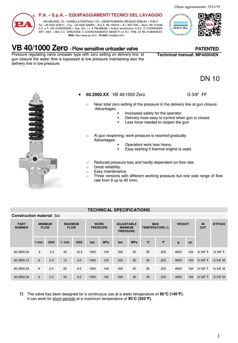
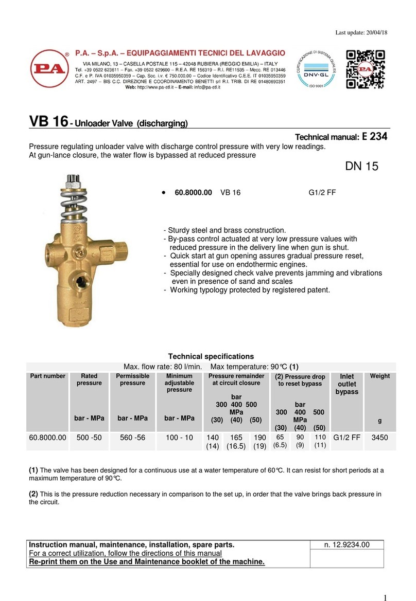
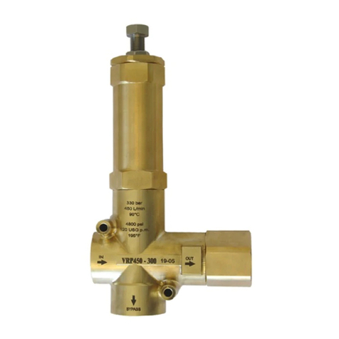
VB 200/280
Unloader valve
Technicalmanual:E269
Pressure regulating unloader valve. At gun closure the water flow is discharged in bypass, lowering the
pressure in the circuit upstream of the valve.
DN 25
Technical specifications
Construction material Brass body and Sst internal parts
Rated temperature (1) 90°C (195°F)
Rated
pressure
Permissible
pressure
Minimum
adjustable
pressure
% decrease of
pressure to
reset working
pressure (2)
Max. Flow Rate
Weight
Part number
bar Psi bar Psi bar
Psi % l/min
USGpm g lbs
Inlet
Outlet
Bypass
60.4300.00
280
4050
310
4500 28
410 22 200
53 3440 7.6 G 1” F
1)
The valve has been designed for a continuous use at a water temperature of 60°C. It can resist for short periods
at a maximum temperature of 90°
2) When the valve is in bypass mode, this is the decrease of pressure that has to occur in the circuit downstream
of the valve, in order that the valve can restore the working pressure in the system. The indicated figure is
expressed as a percentage of the pressure setting (working pressure).
At gun closure, a pressure increase occurs in the circuit downstream of the valve. This pressure increase is used to
activate the valve and discharge all the flow in bypass. The value of the pressure increase can not be calculated. It
depends on the correct setting of the valve (see PRESSURE ADJUSTMENT/SETTING) and on the layout of the system:
flow rate, working pressure, length and characteristic of the tubes, closing time of the gun.
•
60.4300.00 VB 200/280 1”G FF
oHigh flow rate
oBrass body and Sst internal parts
oAdjustable with screw and counternut to secure the working
pressure
o
Slots for screw fastening

Ultimo aggiornamento: 14/02/11
2
DIMENSIONAL DRAWING
SELECTION
This product is intended to be incorporated on a finished machine. This product is to be utilized with clean fresh water, even slightly
additivated with normal detergents. For use involving different or corrosive liquids, contact the PA Technical department. Appropriate
filtration should be installed when using impure liquids. Choose the valve in line with the working data of the machine where to be
installed (permissible pressure, maximum flow rate and rated temperature of the system). In any case, the pressure of the machine
must not exceed the permissible pressure imprimed on the valve.
OPERATIONS
The valve regulates the maximum pressure of the system by variating the flow discharged through the bypass. The adjustment is
made by altering, by means of a piston, the position of a shutter which partially closes the bypass opening. At gun closure, a check
valve closes isolating the part of the circuit downstream of the valve: the pressure increase that remains trapped is used to activate
the complete aperture of bypass. All the flow supplied by the pump is therefore discharged at low pressure through the bypass and the
pump works at low pressure.
INSTALLATION
This accessory, on a system that produces hot water, must be fitted upstream of the heat generator. On a system that generates hot
water, it is advisable to fit in accessories that limit the accidental increase of fluid temperature.
Always install a safety valve.
It is recommended to use a nozze with a flow rate that, at gun opened, allows to discharge from the valve bypass at least 5% of the
flow supplied by the pump in order to obtain a constant pressure figure, and easy adjustment and to avoid troublesome pressure
spikes at gun closure.
If the nozze wears out, the working pressure decreases. To reset pressure back to work level, it is necessary to replace the worn out
nozzle. When a new nozzle is fitted, re-setting of the system to its original working pressure is necessary.
DISCHARGE SYSTEM AND WATER ADDUCTION
It is recommended to install the valve with bypass discharge into a tank. We advise also that the tank be fitted with deflectors in order to
reduce eventual turbolence and air bubbles, generated by the immission of the bypass flow, which could be harmful for the pump. With
elevated flow or near to the maximum flow of the valve, the installation with bypass recycle direct to the pump could cause harmful
pressure spikes, resulting extremely dangerous for the pump.

Ultimo aggiornamento: 14/02/11
3
PRESSURE REGULATION/SETTING
The desired working pressure must be adjusted while the system is in operation and gun opened. Alter the pressure by screwing or
unscrewing the adjustment screw. The operation is easier if the correct nozzle has been chosen (see paragraph “installation”). Pressure
is increased by rotating the adjustment knob. In case pressure does not increase despite turning of the knob, do not force, but check
that the nozzle flow rate/pressure ratio is correct.
ATTENTION: The nut in position 16 is a mechanical security device that limits the maximum pressure; it must absolutely not
be removed.
TROUBLE SHOOTING: CAUSES AND SOLUTIONS
PROBLEMS PROBABLE CAUSES SOLUTIONS
Frequent unloader recycles Damaged check valve O ring
Leaking connections
Restricted bypass
Replace
Check and renew
Clean or adapt
Unloader does not reach
pressure
Piston O rings worn out
Debris between seat and shutter
orn out nozzle
Replace
Clean the seat
Replace
Pressure peaks There is not a min of 5% of total flow in bypass
Excessive flow in bypass
Spring totally compressed
Reset
Change type of valve or adjust passages
Loosen screw and change nozzle
Unloader does not bypass at
low pressure
Jammed check valve
Debris on check valve
Clean or replace
Clean
MAINTENANCE
STANDARD: every 400 working hours, check and lubricate the seals with water resistant grease.
SPECIAL: every 800 working hours, control the wear of the seals and internal parts and if necessary, replace with original PA parts
taking care, during installation, to lubricate with water resistant grease.
Maintenance has to be carried out by specialized technicians.
The manufacturer is not to be considered responsible for damage as a result from incorrect fitting and maintenance.
REGULATIONS : see Norm Manual
The accessory hereby described bears the CE marking in accordance with the standards and directives published in the Declaration of
conformity.
For a correct utilization, follow the directions described in this manual and re-print them on the Use and Maintenace manual of the
machine.
If needed ask for the original Conformity Declaration for the accessory chosen. The present manual is valid for all unloader valves
named VB 200/280.
Technical data, descriptions and illustrations are indicative and liable to modification without notice.
Instruction manual, maintenance, installation, spare parts.
n. 12.9269.50

P.A. SpA EQUIPAGGIAMENTI TECNICI DEL LAVAGGIO
Via Milano, 13 42048 Rubiera - (RE) ITALY
Tel +39 0522 623611 (ric aut) - Fax +39 0522 629600
This manual suits for next models
1
Other PA Control Unit manuals
Popular Control Unit manuals by other brands

AnaCise
AnaCise Platform Interface Module GigE Triple Play PIM PIM... Specification sheet

Sinope
Sinope Senda VA4220WF installation guide

Cypress
Cypress CYW43353 manual

Aumuller
Aumuller EMB 7300 Installation and commissioning instructions

SMC Networks
SMC Networks VR51 Installation and maintenance manual

Coelbo
Coelbo SWITCHMATIC 1 Advanced Settings