Pace ThermoFlo 6008-0145-P1 User manual

1
ThermoFlo Blower Assembly
(for PACE ThermoFlo power sources)
P/N 6008-0145-P1
InstallationInstructions
Manual Number 5050-0431
Rev. A
For any questions regarding these instructions, contact the PACE Service
Department directly at:
Telephone (888) 535-PACE, Fax (301) 483-7030
PACE Incorporated
9893 Brewers Court
Laurel MD 20723-1990

2
To replace the Blower Assembly, perform the following procedure step by step, in
sequence using the accompanying illustrations as a guide.
CAUTION
POTENTIAL SHOCK HAZARD - Disassembly of the ThermoFlo power
sourceexposeslinevoltageparts. ReplacementoftheBlowerAssembly
mustbeperformedbyqualifiedservicepersonnelonly. Servicepersonnel
mustinsurethattheACpowercordisdisconnectedpriortodisassembly.
Contact the PACE Service Department for assistance at tel.1-888-535-
PACE, FAX 1-301-483-7030.
1. Place the unit on a suitable work surface with the front of the power
source facing forward.
2. Disconnect the AC power cable from the unit (if present).
NOTE
Use all ESD control precautions when servicing the ThermoFlo system.
Thepowersourcecontainsassembliesutilizingstaticsensitivecomponents.
3. Remove the 10 Front Panel mounting screws.
4. Pull the Front Panel forward.
5. Disconnect the ribbon cable from the Front
Panel by pulling the 2 plastic locking tabs
away from the ribbon cable (see illustration)
then pulling the ribbon cable out of the Front
Panel connector. Set the Front Panel aside.
6. Reposition the unit with the rear of the power
source facing forward.
7. Remove the 8 Rear Panel
mounting screws.
8. Gently pull the Rear
Panel away from the
power source. Attached
to the Rear Panel are
the main PCB and the
Chassis. Pull these
parts completely out of
the power source case.
Set the power source
Case aside.

3
9. The COM Port is located on the upper
right portion of the Rear Panel.
Remove the two (2) Mounting Nuts
located on either side of the COM Port.
10. Position the Chassis as shown with the Blower Assembly facing
forward.
11. Disconnect the four (4)
connectors shown from the
Main PCB. Make note of
the location of each
connector (the Flo Pump
harness plug should be
marked "P10").
13. Pull the Main PCB forward to release pins on PCB plug from the
connector on the HV Board. Set Main PCB aside.
12. Disconnect the two (2)
connectors shown from the
main PCB.
CAUTION
The larger of these two
connectors has very fine wires
attached. Handlethisconnector
withcaretopreventanydamage
to these wires.

4
14. Remove the Tie Wrap that secures the large air hose to the Blower
Assembly (see illustration, step 24). Do NOT remove the other 2 Tie
Wraps (near rear panel).
15. Remove the 4 Hex Nuts & Washers from blower mounting bracket.
16. Pull the Blower Assembly up and just off of its four (4) mounting studs.
17. Holding the Blower Air Hose, pull the Blower Assembly forward to
release the Air Hose from the Blower Assembly.
18. There are four (4) Blue grommets (with metal sleeves) on the blower
mounting bracket. Remove each of the grommets and install in position
on the replacement Blower Assembly. Set old Blower Assembly aside.
19. Holding the Blower Air Hose, push the nipple
of the plastic housing on the Blower Assembly
forward and into the Hose.

5
20. Push the Blower Assembly down, sliding the four (4) Blue grommets
(with metal sleeves) over the four (4) mounting studs on the chassis
plate.
NOTE
Insure that the small Vacuum Air Hose does not become pinched when
the Blower Assembly is pushed into place. This hose should be routed
under the Blower Assembly between the plastic blower housing and the
metal blower mounting bracket.
21. Check the Blower Air Hose to insure that it is securely attached to the
Blower Assembly and is straight (not kinked). Adjust hose if necessary.
22. Secure the Blower Assembly in position by installing the four (4) Hex
Nuts and Washers removed in step 14.
23. Route the two (2) Blower Assembly wires (with connector) between the
Blower and Flo Pump Assemblies then between the Flow Pump
Assembly and the transformer. Refer to Blower Assembly illustration,
page 4.
NOTE
Insure that the plug pins are lined up correctly with the connector. The
system will not operate if this connection is incorrect.
24. Secure Blower Air Hose (and wire
harness) at the Blower Assembly
using the supplied Tie Wrap.
25. Position the Main PCB as shown
over the Chassis and with the ribbon
cable facing forward.
26. Align the COM Port receptacle at
the rear of the Main PCB with its
rear panel cutout
27. There is a ten (10) pin plug mounted
at the rear of the Main PCB.
Carefully insert these pins into the
matching 10 pin connector on the
HV Board.

6
28. Install the two (2) Mounting Nuts
removed in step 9 on either side of the
COM Port.
29. Install the 6 connectors
removed in steps 11 & 12.
Insure that each connector
is pushed fully onto its
PCB connection. Insure
that the connector marked
"P10" is plugged into the
proper location. Refer to
illustration.
30. Slide the Chassis into the rear of the Case with the Main PCB
positioned as shown in the illustration below. Located at the front,
inside of the Case are two (2) mounting studs with Blue grommets. The
two (2) slots at the front of the inner chassis plate must slide into the
slots in the two (2) Blue grommets.
NOTE
Wire harnesses are located along the edges of the Chassis. Insure that
thesewiresdonotgetcaughtorpinchedagainsttheedgesoftheChassis,
Case or the rear panel as the Chassis slides in.
VIEWED FROM REAR VIEWED FROM FRONT

7
© 1998 PACE Incorporated, Laurel MD. All rights reserved. Printed in the U.S.A.
31. Install the 8 Rear Panel mounting screws removed in step 7.
32. Position the power source facing forward.
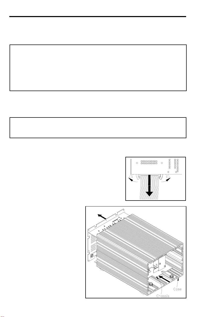
33. Connect the ribbon cable (removed in step 5) to the Front Panel
Connector; the two (2) plastic locking tabs will automatically lock the
cable in position when it is fully seated in the connector.
34. Install the 10 Front Panel mounting screws removed in step 3.
Additional copies of this manual or other PACE literature may be obtained from:
PACE Incorporated (301) 490 - 9860
Sales Administration (301) 498 - 3252 Fax
9893 Brewers Court
Laurel MD 20723-1990
Since 1958, PACE Incorporated has provided
advanced technology training in all aspects of hand
soldering, rework and repair.
PACE Incorporated retains the right to make changes to specifications contained
herein at any time, without notice.
Contact your local authorized PACE Distributor or PACE Incorporated to obtain the
latest specifications.
The following are registered trademarks and/or servicemarks of PACE
Incorporated, Laurel Maryland U.S.A. and may only be used to identify genuine
PACE products or services:
AdapTip, Arm-Evac, Cir-Kit, ComForm I, ConducTweez, CRAFT,
Dual Path, Flo-D-Sodr, FuseSet, HandiPik, HotSpot, LapFlo, MBT,
Micro Portable, MicroChine, MiniChine, Mini-Wave, PACE, Pacenter,
Ped-A-Vac, PETS, Pik-Vac, PRC, Prep-Set, Pro-Evac, Redi-Rak,
ResisTweez, SensaTemp, Snap-Vac, Sodr-Pen, Sodr-X-Tractor, SR-3,
SR-4,ST,StripTweez,SwaPlater,ThermoBond,Thermo-Drive,ThermoJet,
ThermoPart,ThermoPik,ThermoTweez,Tip-Evac,Ventur-EvacVisiFilter.
The following are trademarks and/or servicemarks of PACE Incorporated, Laurel
Maryland U.S.A. and may only be used to identify genuine PACE products or
services:
Heat Wave, Pik-Tip, Pulse Plate, Sodrtek, ThermoFlo, Toolnet.
Table of contents
Popular Blower manuals by other brands

F.F. Group
F.F. Group GHB 223 PLUS Original instructions

Shindaiwa
Shindaiwa 68907-94311 Owner's/operator's manual

Craftsman
Craftsman 358.797203 instruction manual

Frigidaire
Frigidaire PL36DD installation instructions

Maktec
Maktec MT401 instruction manual

Tornado
Tornado 96160 Operation & maintenance manual

McCulloch
McCulloch MB320BV Operator's manual

Homelite
Homelite UT08120 Operator's manual

GreenWorks Pro
GreenWorks Pro ULTRAPOWER 60X RANGE BLC402 Operator's manual

Stihl
Stihl BGA 86 instruction manual

Expand-it
Expand-it Expand-it UT15519E Operator's manual

SNOWJOE
SNOWJOE SUNJOE 24V-TB-LTE-P1 Operator's manual