Drain
Plug Fill
Plug
Fig. 16
Fig. 17
Fig. 18
6
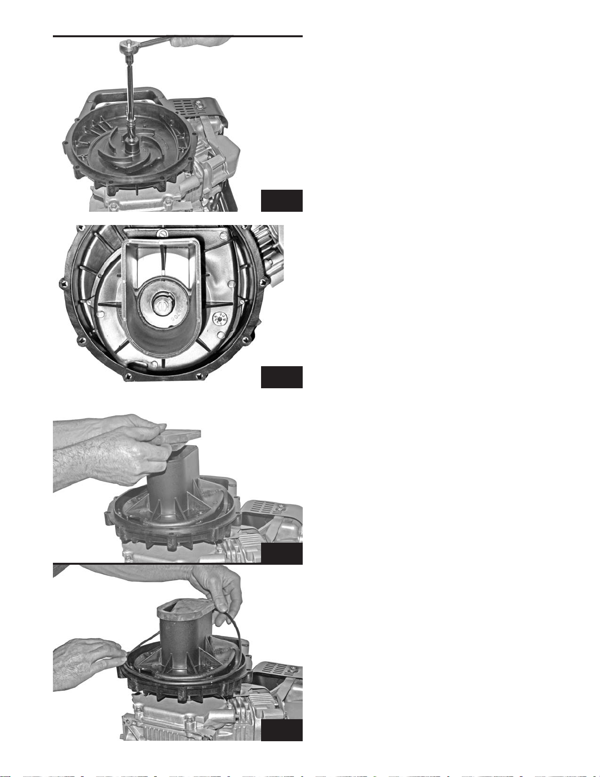
12) Place the pump body (Ref. #42) onto the
bracket so the discharge opening (large hole on
side of body) is toward the bracket handle (Fig.
#16). Install the ten body screws (Ref. #21). You
will need a 3/8" socket or flat head screwdriver
for the screw head.
13) Tighten the screws in a clockwise rotation
aroundthe pump (Fig.17). Startatthe screw just
to the left of the drain plug (Ref. #23). Tightening
inthissequencehelpspreventpinchingthecheck
valve and body o-ring.
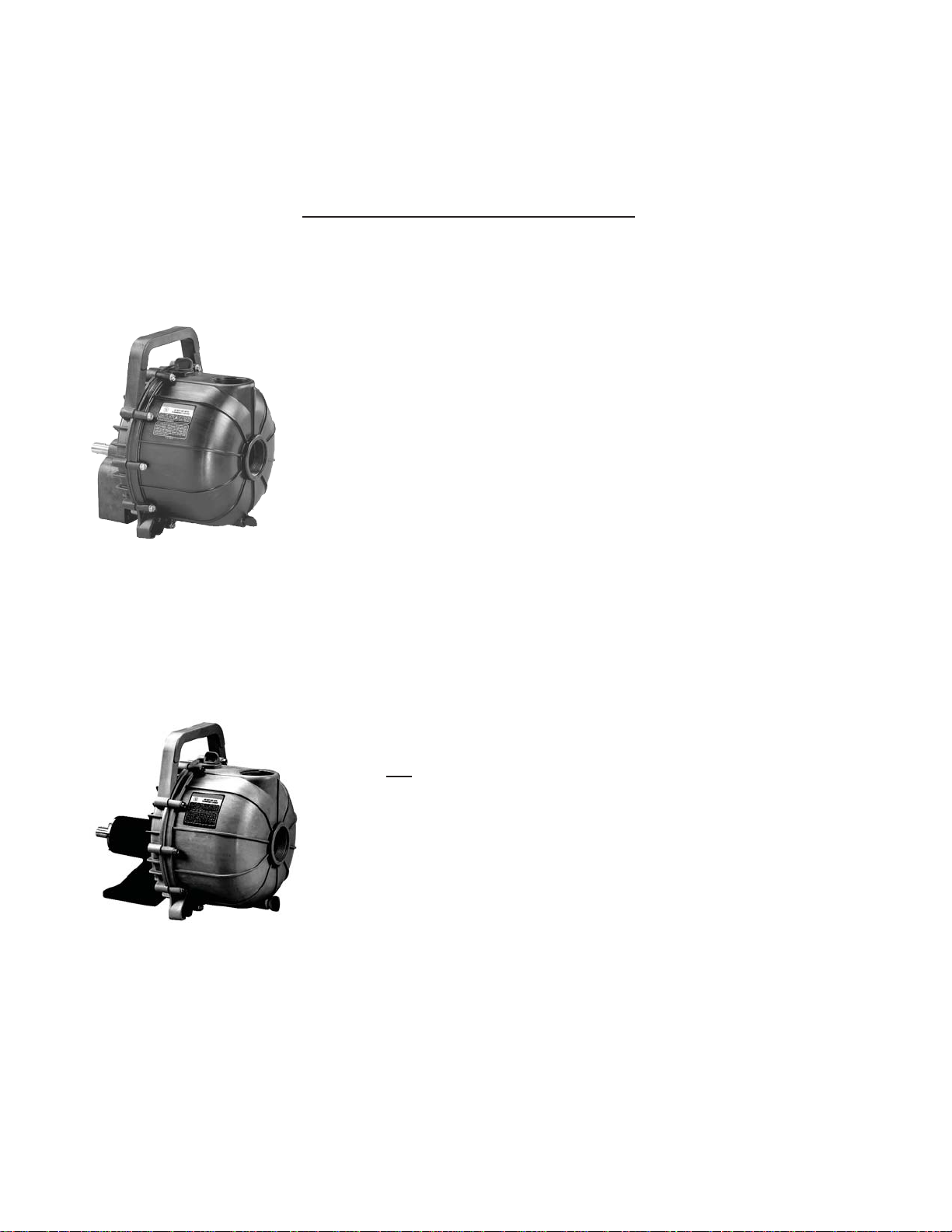
14) Placeo-rings(Ref.#25&22)onthefillerplug
(Ref. #24) and drain plug (Ref. #23).
15) Install the drain plug and filler plug (Fig. 18).
Tightenonlyhandtight.DONOTUSEAWRENCH.
16) Apply the appropriate labels to the pump.
The red, white & black warning label should be
applied on the left side of the pump body. The
pump model number label should be applied on
the right side of the pump body.
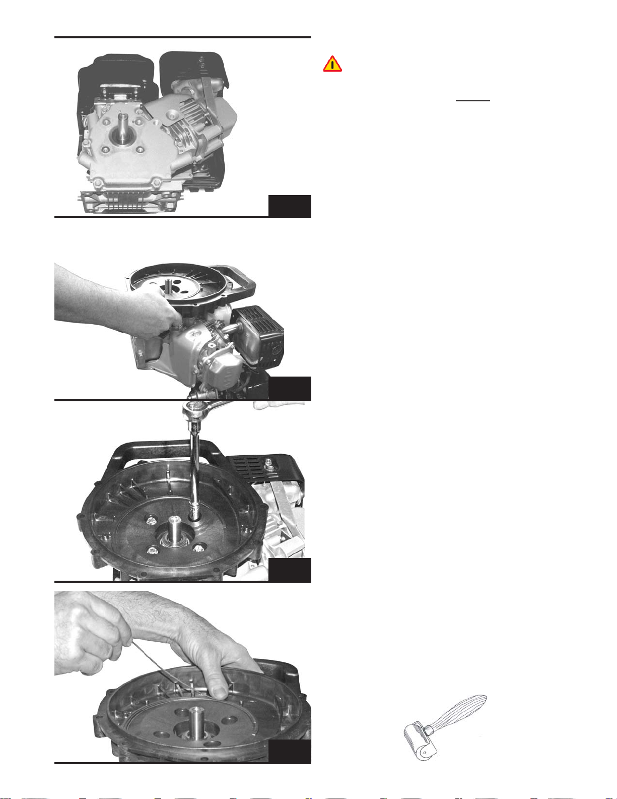
17) With pump fully assembled, turn the drive
shaft to insure clearance of impeller between
the bracket and volute face. Should you hear an
internalscrapingnoise,disassemblethepumpto
the impeller. Adjust amount of impeller shims to
correct the problem. Reassemble and check for
clearance one more time.
18) Use Teflon tape when install-
ing threaded fittings or elbows in the
pump discharge and suction. 1½" or 2
fittings - 10-12 wraps of Teflon®tape on the
suctionfittingsandelbow,6wrapsondischarge
nipple. 3" fittings - 15 wraps with ¾" Teflon®
tape on suction, discharge and elbow fittings;
6 wraps on discharge nipple.
DO NOT OVERTIGHTEN. ONE FULL TURN
WITHAWRENCH PASTHAND TIGHTis usually
sufficient to prevent leakage.
19) Afterpumpassembly,refertopumpoperator's
manual for proper operating procedures.