- DO NOT connect it directly to the battery.
Doing so will cause battery drainage
when engine is not running.
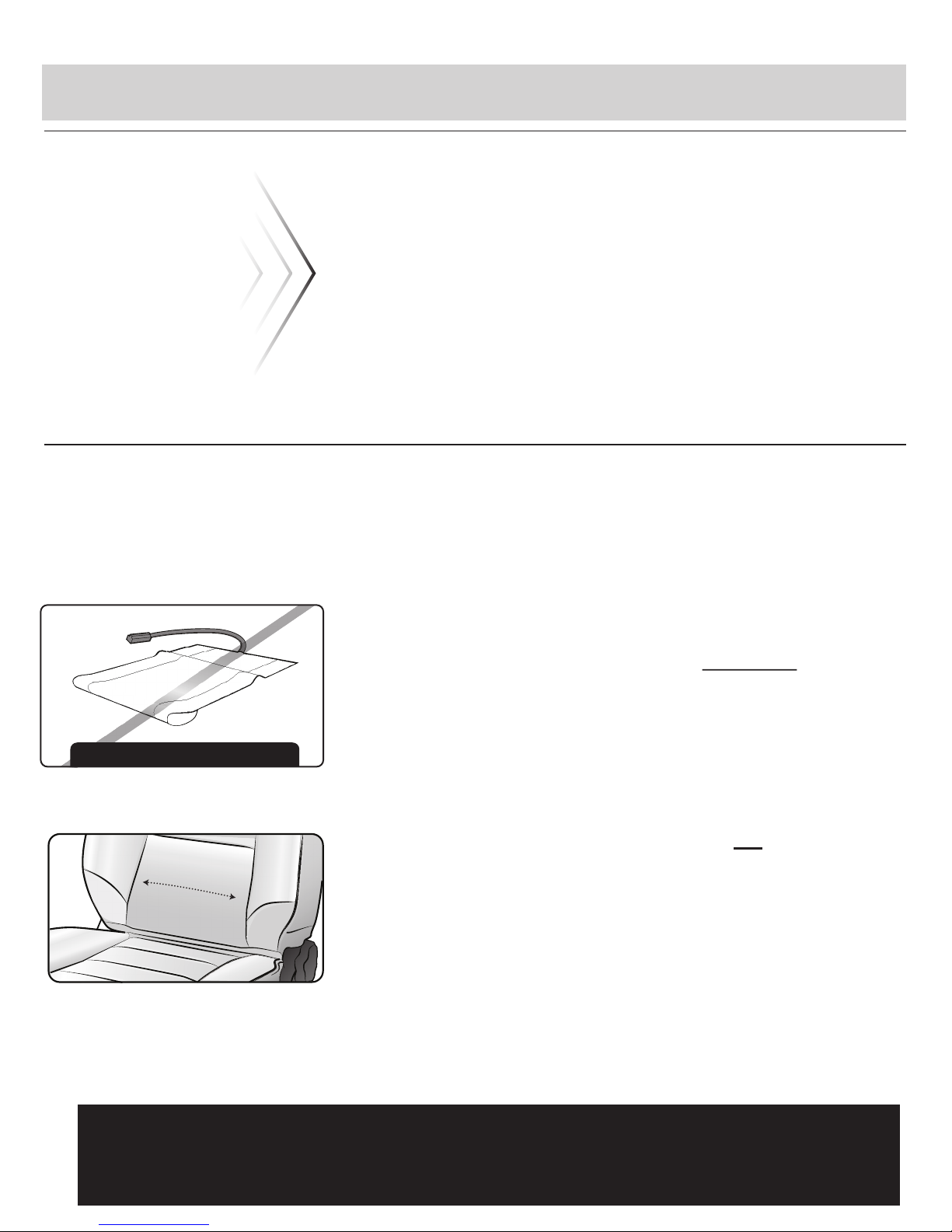
Once a power source is located,
extend the “Power Wires” underneath
the vehicle’s trim or carpet to the seat
bottom. Keep enough length for the
seat to slide all the way forward and
backward. Make sure the end with a
connector is the end by the seat.
Never install wiring directly under
an occupant’s feet area.
9.
10.
11.
12. Find a suitable surface that is flush
and has enough space to fit the
universal switch and wires behind it.
The switch is often installed on either
the plastic section of the seat’s side
or in the center - portion of the dash.
Once you have found the right
location, drill a 21mm (13 /16 inch)
hole through the desired surface and
pull the switch wiring pigtail though
the hole. Attach the switch wiring
pigtail to the main wiring harness
(underneath the trim) and push the
switch firmly in the hole until you
hear a “Click”.
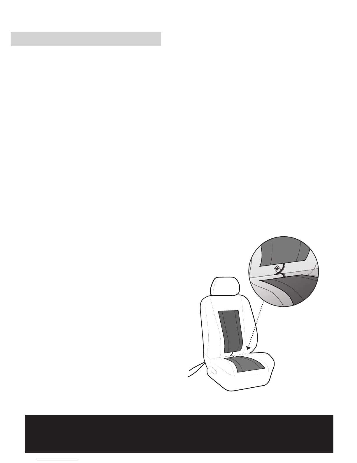
After securing the heating pad to seat
foam, put the seat cover back on with
any seat plastics or upholstery that
you previously took out.
Locate an onboard accessory
triggered power source (supplies
current only when the key is in ACC
position) which is able to deliver up
to 8 Amp current. This source may be
located in your vehicle’s fuse box,
- See the vehicle owner’s manual to
help find the location of an appropriate
power source or talk to your supplier
about other options (such as “Fuse Stackers”
or “Power Distribution Bypass Modules”).
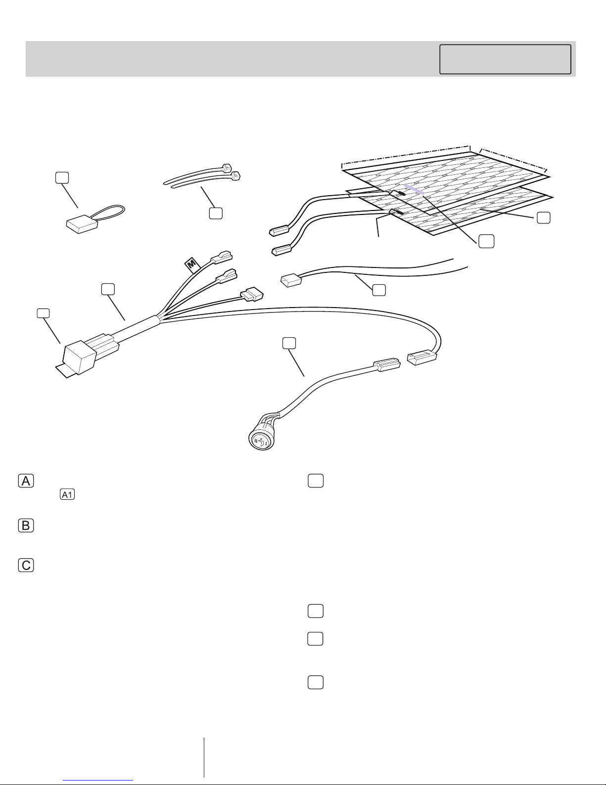
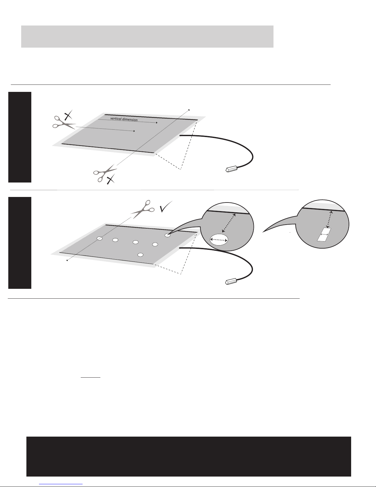
Carefully cut away the marked
material making sure
NOT to cut the conductor buss lines.
7.
8. Remove the adhesive tape backing
from the bottom side of the seat
heater pad and carefully place the
pad on the seat in the desired location.
The holes you cut should align with the
listing.
Make sure pad is not bent and folded
(See Fig. 3-2 on page 5). This step is
crucial in maintaining safety and
warranty of this product.
INSTALLATION PROCEDURE CONTINUED . . .
9
DO NOT BEND OR FOLD PAD
Fig. 3.2
IMPORTANT
The installation method laid out in this manual affords the highest level of user
safety and optimal performance for this equipment.
Warranty for this equipment remains valid ONLY when the installation method
and recommendations presented within this manual are fully adhered to.
Please Read
The switch head is keyed
(notched) so that you may align it
properly in your mounting hole.
This notch is located on the side of the switch
head opposite to the LED and is 7/16” in length.