Pacific Recorders & Engineering Corporation BMX User manual

www.SteamPoweredRadio.Com
• .
BMX TECHNICAL MANUAL
Section 1 GENERAL INFORMATION
1.1
Introduction
1.2 Description
1.3 Specifications
1.4 Dimensional Drawings
Section 2 INSTALLATION
2.1
Introduction
2.2 Grounding
2.3 Cable Preparation
2.4 Power Supply Connection
2.5 Audio Circuits Connection
2.6 Logic Circuits Connection
2.7 Microphone Module Logic
• 2.8 Line Module Logic
2.9 Warning Command Logic
Section 3 SET
UP
AND OPERATION
3.1
Operating Controls
3.2 Level Alignment
3.3 Audio Patch Facilities
Section 4 EQUIPMENT DESCRIPTION
4.1
Mainframe
4.2 Power Supply
4.3 Microphone Input Module
4.4 Line Input Module
4.5 Stereo Output Module
4.6 Monaural Output Module
4.7 Control Monitor Module
4.8 Studio
Monitor
Module
4.9 Remote Switcher Module
•
8-79

www.SteamPoweredRadio.Com
•
•
•
Section 5 MAINTENANCE
5.1
Routine Maintenance
5.2
Trouble Shooting
5.3
Spare Parts
Section 6 OPTIONS AND MODIFICATIONS
6.1
Microphone Input Module
6.2 Line Input Module
6.3
Utility
Mix Buss
Section 7 DRAWINGS, SCHEMATICS AND
PARTS
LISTS
7.1
Stereo Block Diagram
7.2
Connector Panel Diagram
7.3
Mainframe Wiring
7.4
Microphone Input Module -Audio
7.5
Microphone Input Module -Logic
7.6
Line Input Module -Audio
7.7
Line Input Module -Logic
7.8
Control Room
Monitor
Module
7.9
Control Room
Monitor
module -Switching
7.10 Studio Monitor/Talkback Module
7.11
Studio Monitor/Talkback Module -Switching
7.12 Stereo Line Output Module
7.13
Monaural Line Output Module
7.14
Timer Control Panel
7.15
Remote Line Selector Module
7.16
Meter
Buffer
Amp
7.17
50-1
Power Supply
7.18
50-2
Power Supply
7.19
99-73 Power Supply
7.20 Parts
List
Section 8 ADDENDUMS
8-79

www.SteamPoweredRadio.Com
•
•
•
BMX TECHNICAL MANUAL
Section 1 GENERAL INFORMATION
1.1
INTRODUCTION
This manual is designed
to
provide the necessary information required
to
under-
stand, install, operate, and maintain the series BMX broadcast audio console. It is
assumed that the reader has a working knowledge
of
audio control consoles,
systems, and installation practices. The BMX series console, however, is a
sophisticated device featuring many advanced technologies. Should you
en-
counter any
difficulty
during installation or initial operation, we recommend that
you contact the factory
for
assistance. Each BMX console is configured
to
the
customer's specifications, thoroughly tested, and burned in for over one hundred
(100)
hours prior
to
shipment.
1.2 DESCRIPTION
The BMX console is a high performance, compact, audio-control system designed
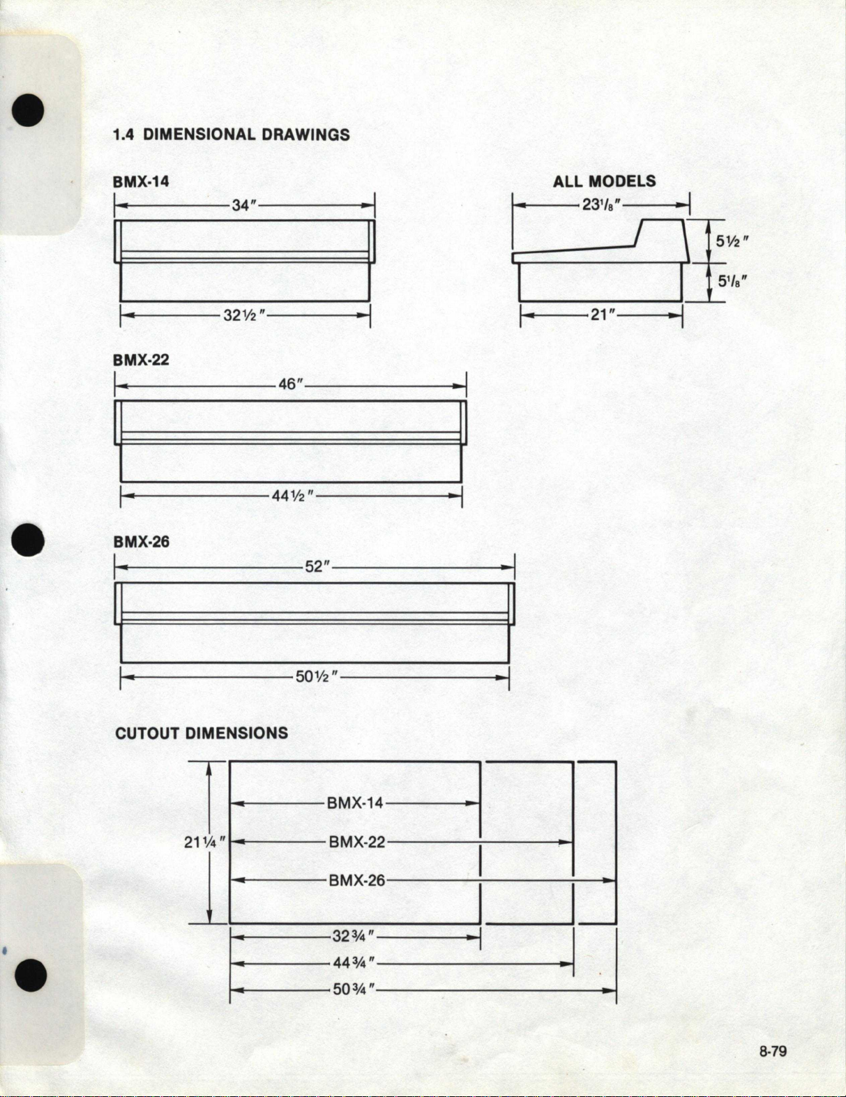
to meet the most exacting on-air broadcast requirements. There are three BMX
mainframe sizes available which will accommodate
14,
22
and
26
input modules.
These mainframes feature identical output channel, monitoring, and remote line
switching functions. In order
to
realize the maximum potential
of
a BMX console,
it
is important that the user fully acquaint himself with, not only the audio mixing
and control functions, but also realize and appreciate the extensive logic functions
designed
to
control and
be
controlled by the peripheral equipment. The accom-
panying block diagram shows, not only the audio signal flow, but also details the
numerous control command inputs and outputs that are available to the user at
both microphone and line input positions.
Most
of
these logic control functions
have not been previously available in
an
off-the-shelf console. Indeed, most
of
these features were developed in our System One series custom consoles and,
therefore, have proved their utility, functionality, and reliability in major broadcast
installations over the past four years. The block diagram presents a concise pic-
ture
of
the internal workings
of
the complete console system. This diagram can be
very useful in determining how best
to
utilize your BMX console,
as
a reference
to
understanding the operating functions and features, and for use in trouble
shooting.
The console has been designed functionally, mechanically, and electronically
to
provide the maximum in performance for
cost
of
any currently available broadcast
console. Highest quality components are used throughout the console. Glass
epoxy
P.C.
Boards
with
gold-plated contact fingers mate
with
bifurcated gold-
plated edge connectors. Potentiometers are low-noise, conductive plastic con-
trols, and switches are wiping-action, low-noise, long-life units.
8-79

www.SteamPoweredRadio.Com
•
•
•
The gain structure of the console is such that normal operation is easily achieved
without danger of internal clipping while operating the amplifiers at optimum
signal
to
noise conditions. The standard input modules accommodate the range
of
input levels normally found in broadcast operations without the use of external
pads
or
amplifiers. A patch point is provided at each input position after the input
amplifier and before the fader. This is the optimum point at which
to
insert exter-
nal processing devices such as limiters and equalizers. Patch points are also pro-
vided in each output channel after the mixing amplifier and before the line output
amplifier.
All console inputs and program outputs are transformer isolated for best noise
re-
jection, simplified system grounding, and maximum protection against auxiliary
equipment failures. When properly installed, using the information in this manual,
the BMX console is free
of
internal switching pops, clicks, and
RFI.
The separately packaged power supply is fully regulated and is protected with
fuses as well as electronic safeguards against excessive current and line-voltage
fluctuations. The power supply provides three separate voltage outputs. Two of
these outputs,
±
16
volts are used to power the audio circuitry. The third output,
+
12
volts, is used
to
power the logic control circuitry, lamps, and relays. An
op-
tional
+
48
volt output is available for the powering
of
condenser microphones
connected
to
the console.
8-79

www.SteamPoweredRadio.Com
•
•
•
1.3 SPECIFICATIONS
Microphone
Input
Source
Impedance
150
ohms
Input
Impedance 10 times
source
impedance,
balanced
and floating
Input
Level
Adjustable
from -
60dBv
to
-
35dBv
(Reference 0.775V)
Input
Headroom
Greater
than
30dB above
nominal
input
level.
High Level
Input
Source
Impedance
600
ohms
Input
Impedance
1
OK
ohms, balanced and
floating
Input
Level
Adjustable
from -
12dBm
to+
8dBm
Input
Headroom
Greater
than
30dB
above
nominal
input
level.
Program,
Audition,
Monaural
Outputs
Load Impedance
Source
Impedance
Nominal
Ouput
Level
Maximum
Output
Level
Output
Headroom,
above+
8dBm
600
ohms
Less
than
95
ohms
+ 8
dBm
, adjustable
+ 28
dBm
, 600 ohm load
Greater
than
20dB
Monitor
Outputs
Main
Output
Output
Impedance
Load Impedance
Output
Level
Headphone
Output
Output
Impedance
Load
Impedance
Output
Level •
Cue
Output
Output
Impedance
Load Impedance
Output
Level
600
ohms,
unbalanced
5K
ohms
or
greater
0
dBm
nominal, + 20dBm
Maximum
75 ohms, resistor feed
8
ohms
or
greater
0
dBv
nominal, + 20
dBv
maximum
. (Reference
0.775V)
10
ohms
45
ohms
or
greater
0
dBv
nominal
, + 20
dBv
maximum
.(Reference
0.775V)
Frequency
Response
Microphone
Input
(150
ohm)
to
program
output
20Hz
to
15KHz + 0, - 1
dB
20Hz
to
20KHz + 0, - 1.
5dB
Line
Input
(600
ohm)
to
program
output
20Hzto
15KHz
+o,
-
1dB
20Hz to 20KHz + 0, - 1.
8dB
Noise
Microphone
Input
Amplifier
High Level
Input
Amplifier
Output
noise with
one
microphone
channel
ON,
fader
at -
15dB
attenuation,
input
sensitivity
at
-50dBv
Output
noise
with
one
Line
channel
ON,
fader
at -
15dB
attenuation,
input
sensitivity at
+8dBm
Output
noise
with
no
input
channels
on
-127dBvRMS (reference
0.755V) equivalent input
noise, 150 ohm source,
20KHz
band
width
-112dBm
RMS,
equivalent input noise,
600 ohm source, 20KHz
band
width
-
75db
below output,
(reference + 8dBm),
150
ohm
source,
20KHz bandwidth
-
82db
below
output
,
(reference + 8dBm), 600
ohm
source, 20KHz
bandwidth
-84dB below output,
(reference + 8dBm),
20KHz
bandwidth
Distortion, T.H.D.
Microphone
Input
to
Less than 0.025% at
program
output
1KHz, Less than 0.
3%
at
Line
Input
to
program
output
+ 28dBm, 30Hz
to
20KHz
Less than 0.015% at
1KHz, Less than 0.3% at
28dBm, 30Hz to 20KHz
Distortion, I.M.
Microphone
Input
to
program
output
( +
8dBm)
Line
Input
to
program
output
( + 8dBm)
Less than 0.02% SMPTE
Less than
0.01
%
SMPTE
Square
Wave Response
Microphone
Input
to
program
output
Line
Input
to
program
output
Rise
time
less
than
10
µsec.
Overshoot
or
ringing
: None
Rise
time
less than
12 µsec. Overshoot
or
ringing
: None
Crosstalk
Adjacent
busses, all
bus
assignments
on
,all
inputs
on
Less
than
-85 dB at 1KHz
Less
than
-
75
dB at
20 KHz
8-79

www.SteamPoweredRadio.Com
•
•
•
•
1.4
DIMENSIONAL DRAWINGS
BMX-14
ALL
MODELS
,
..
34"
..
, 231
/e"
If
f 1
I
..
32½"
..
,
I·
21"
BMX-22
46"
~
I
44½"
BMX-26
52"
~
I
50½"
CUTOUT
DIMEN:Sl=O~N~S------7
T
'----
BMX-14
BMX-22
211
¼"
BMX-26
----f---117
_____
32¾"
------~•
-.. I
44¾"
-
'-----
50¾"
'-----
·I
tt½·
51
/e"
..
I
8-79

www.SteamPoweredRadio.Com
•
•
•
Section 2 INSTALLATION
2.1
INTRODUCTION
Installation of the BMX is remarkably easy for a console
of
its sophistication. The
console is physically installed by setting
it
into a cutout in the work surface
of
the
studio cabinetry. Signal and power connection to the console is made to the con-
nector panel located at the rear of the console. This panel is recessed to provide
the broadcaster flexibility of wire routing in console installation. Care should
be
taken to avoid locating the console within six feet of any intense electromagnetic
hum fields such
as
are produced by large power transformers and motors.
Likewise, cables
to
and from the console should
be
routed to achieve maximum
practical distance from
AC
power wiring.
Before beginning the installation, a plan should
be
drawn up showing how support
equipment will
be
connected to the console. All cables and connectors should
be
tagged with legends and/or numbers, and logged.
2.2
GROUNDING
Grounding in modern broadcast consoles is more critical than older devices
of
more limited band-pass capabilities. Achieving low ground system impedance
within a small piece
of
equipment is relatively easy. However, the problem
becomes progressively more
difficult
as
the system becomes larger. In designing
the
BMX,
much thought was given
to
system grounding requirements and the
elimination of
DC
path ground loops. The rules are simple and logical:
1.
The shield pins
on
each console connectorare connected directly to the con-
sole system ground.
2.
Shields of cables connecting to any auxiliary equipment should not
be
ter-
minated to the ground
of
that equipment.
3. A separate ground wire from the console and from each piece of auxiliary
equipment should then
be
run to a system ground point in accordance with the
station's grounding procedure.
2.3 CABLE PREPARATION
Only unspliced, preferably new, cables should
be
used in connecting the console.
Audio connections should
be
made with
two
conductor insulated foil shielded
cable with drain wire. This cable should
be
equivalent
to
Belden types
8451,
9451,
or
8761.
The molex pins are constructed so that the short crimp ears attach to the non-
insulated end of the wire and make electrical contact, while the long crimp ears at-
tach to the insulated section of wire and
heJp
support the connection. Insulation
and
foil shield on cables should
be
stripped back about 1½ inches. Shield drain
wire should
be
sleeved leaving about 3/16 inch wire exposed. Strip signal wire
in-
sulation back about 3/16 inch.
Insert molex crimp pin into tool notch
"B"
with short ears pointing toward the let-
ter
"B".
Insert the wire Into the terminal so that the stripped portion is between the
8-79

www.SteamPoweredRadio.Com
•
•
•
short crimp ears. Crimp the pin. Place the long ears
of
the pin into tool notch "A".
Crimp the long ears over the insulated section
of
wire. Logic connections should
be made with stranded
22
gauge, multiple conductor jacketed cable. The number
of conductors should
be
determined by application.
Once the pins are crimped, they may
be
inserted and locked into the nylon con-
nector housing; a click can
be
felt indicating that the locking ears
on
the pin have
set. Ifa pin is inserted into the wrong connector position, or
it
is desired to make a
circuit change, simply use the extractor tool supplied to release the pin and press
it out
of
the connector housing.
2.4 POWER SUPPLY CONNECTION
Connection to the powersupply is made with the supplied six-foot cable
to
the
bar-
rier strips
on
the power supply and
on
the console.
Should
it
be
necessary
to
mount the power supply at a distance further than
per-
mitted by the supplied cable,
it
is recommended that a new cable
be
made rather
than splicing a longer length
to
the existing cable. Cable lengths up to ten feet
may
be
fabricated using
16
gauge wire. Cable lengths up
to
20
feet should
be
fabricated with
14
gauge wire. It is very important
to
check and double check the
power supply connections prior
to
turn
on.
An
error in wiring could result in
damage to the power supply and/or console circuitry. The power supply
may
now
be
turned on, at which time, the meter lamps should illuminate. Use
an
accurate
DC
volt meterat the power supply front panel test points
to
verify supply voltages.
It will
be
noted that
two
wires, yellow and green, at the power supply end of the
connecting cable are not connected
to
the power supply barrier strip. These wires
are provided in the event the broadcasterwishes to connect a power supply forthe
phantom powering of condenser microphones. The console mainframe and
microphone modules contain the necessary circuitry to apply powering voltage
to
microphone inputs.
2.5
AUDIO CIRCUITS CONNECTION
Complete information relative to console input, output, and logic terminations is
contained on the interconnection reference drawing. Good wiring practice calls
for care in making each connection,
and
in neatness
of
cable layout. It is very im-
portant to sleeve the cable shield drain wire and sleeve the shield at cable ends
with heat shrink tubing. There is no other means of assuring
an
installation
ac-
cording to recommended grounding procedures.
Throughout the installation, considerable care should
be
exercised to maintain
correct audio phasing. The wiring layout of the connector panel aids in achieving
correct phasing by following a consistent wiring pattern. The shield ordrain wire is
always connected to the
left
connector pin; the low or common wire is connected
to the middle connector pin; and the high or signal wire is connected to the right-
hand pin. A simple visual inspection upon completion
of
installation should reveal
any errors in wire phasing.
8-79

www.SteamPoweredRadio.Com
•
•
•
2.51
MICROPHONE INPUT WIRING
~N~UTJ Typical
for
all
microphone
inputs
PIN#
-A-
-8-
0@@
0@0
000
®®®
A-Input
8-lnput
Preamp
Output
Fader
Input
Notes:
MOLEX
CONNECTOR
A
B
PATCH
PATCH
Shield I
1
1
1
7
Low
2
2
2
8
I
a)
Connector
"A"
and
"B"
pins
#4,
5 & 6 are
not
used on
microphone
input
modules.
High
--PATCH-
b) Patch
connector
pins
#4,
5,
6,
10,
11,
& 12 are
not
used on
microphone
input
modules.
0@@
0@0
000
®®®
®®®
-LOGIC-
c) The PATCH
connector
must bewired sothatthe preamp
output
is connected
through
to
the
fader
input.
If
external
signal processing
or
patch bay equipment is
not
connected
here, amating
connector
with a
jumper
from
pins #3
to
#9
must be installed.
2.52 LINE INPUT WIRING
-A-
·
-B-
-PATCH-
-LOGIC-
Typical
for
all line inputs
MOLEX
PIN#
CONNECTOR Shield I Low I High
A-Input/Left
A 1 2 3
A-Input/Right
A 4 5 6
8-lnput/Left
B 1 2 3
8-lnput/Right
B 4 5 6
PATCH SEND/Left PATCH 1 2 r1
PATCH SEND/Right PATCH 4 5
PATCH RETURN/Left PATCH 7 8
PATCH RETURN/Right PATCH 10
11
12
Notes:
a)
Signal from a monaural source should be wired
to
theLEFTinput.
b) In some installations, it may be operationally more convenient to
connect
a monaural source
to
both left and right inputs. The
bridging-type
inputs
of
the line modules allow them
to
be jumpered
together
without
concern
of
double termination.
c) The PATCH
connector
must be wired so that the PATCH SENDS
are connected
through
to
the PATCH RETURNS.
If
external
processing
or
patch bay equipment is
not
connected here, a mating
connector
with jumpers from pins #3
to
#9 and #6 to #12 must
be
installed.
I C
8-79

www.SteamPoweredRadio.Com
•
•
•
2.53 OUTPUT WIRING
Typical
for
Program,
Audition,
and
Utility
(Mono)
Outputs
fOUTPUT]
LNAME
-MAIN-
MAIN
OUTPUT/Left
MAIN
OUTPUT/Right
-AUX-
0@©
AUX
OUTPUT
/Left
©©@
AUX
OUTPUT
/Right
-PATCH-
PATCH
SEND/Left
0@@
©©@
PATCH
SEND/Right
0@®
PATCH RETURN/Left
®®®
PATCH RETURN/Right
Notes:
MOLEX
CONNECTOR
MAIN
MAIN
AUX
AUX
PATCH
PATCH
PATCH
PATCH
PIN#
Shield I Low I High
1 2 3
4 5 6
1 2 3
4 5 6
1 2
1~
4
5
7 8
10
11
a)
The monaural
output
(optional) appears on
the
LEFT pins
of
the
UTILITY
connector.
b) The PATCH
connector
must
be wired
so
that
the
PATCH SEND
are connected
through
to
the PATCH RETURNS.
If
external
processing
or
patch bay
equipment
is
not
connected
here, a mating
connector
with
jumpers
from
pins
#3
to
#9and
pins
#6to
#12 mustbe
installed.
8-79

www.SteamPoweredRadio.Com
•
•
•
2.54 MONITOR
WIRING-CONTROL
ROOM
and
STUDIO
MONITOR modules.
MOLEX
PIN#
1&2 3&4
0©© 0©©
INPUTS
©@0 INPUTS
©@
0 #1/Left
©0@
0@@
®®®
®®®
#1/Right
5&6 7&8
#2/left
0©© 0©©
#2/Right
©@0 INPUTS ©@0
#3/left
00@
00@
@@@ @@@
#3/Right
STUDIO CONTROL#4/L~ft
ROOM #4/Right
#5/Left
#5/Right
#6/Left
0©©
0©©
#6/Right
0©0
AUX
©@
0
#7
/left
00@
0©@
@®® @®®
#7
/Right
#8
/
left
#8/Right
CONNECTOR
1 & 2
1 & 2
1 & 2
1 & 2
3&4
3&4
3&4
3&4
5&6
5&6
5&6
5&6
7&8
7&8
7&8
7&8
CONTROL ROOM MONITOR MODULE
OUTPUT/Left OUTPUT
OUTPUT/Right OUTPUT
HEADPHONE OUTPUT/Left AUX
HEADPHONE OUTPUT
/Right
AUX
CUE AMP OUTPUT AUX
CUE SPEAKER INPUT AUX
STUDIO MONITOR MODULE
OUTPUT/Left, w/Level control OUTPUT
OUTPUT/Right, w/Level control OUTPUT
OUTPUT
/left,
direct w/muting
AUX
OUTPUT/Right, direct
w/muting
AUX
OUTPUT/Left, direct
w/o
muting
AUX
OUTPUT/Right, direct
w/o
muting
AUX
Notes:
Shield I Low I
1 2
4 5
7 8
10
11
1 2
4 5
7 8
10
11
1 2
4 5
7 8
10
11
1 2
4 5
7 8
10
11
1 2
4 5
1 2
4 5
7 8
10
11
1 2
4 5
1 2
4 5
7 8
10
11
a)
All
monitor
units are bridging, 1
Ok
ohms impedance.
High
3
6
9
12
3
6
9
12
3
6
9
12
3
6
9
12
3
6
3
6
9
12
3
6
3
6
9
12
b) All
monitor
inputs are common
to
both the Control
Monitor
and
Studio modules.
c) The Cue Amplifier
to
Cue Speaker connection is made with
jumpers between pins #8 to
#11
and pins #9 to #12 on the Control
Room Aux
connector
.
8-79

www.SteamPoweredRadio.Com
•
•
2.55 REMOTE LINE SELECTOR WIRING
5&6
0@@
©©©
0©©
@®@
9&10
3&4
©~©@
©©0
000
@®@
7&8
0@(!)
©©0
000
®®@
OUT-1
OUT-2
INPUTS
#1/Left
#1/Right
#2/Left
#2/Right
#3/Left
#3/Right
#4/Left
#4/Right
#5/Left
#5/Right
#6/Left
#6/Right
#7/Left
#7/Right
#8/Left
#8/Right
#9/Left
#9/Right
#10/Left
#10/Right
OUTPUTS
#1/Left
#1/Right
#2/Left
#2/Right
Note:
MOLEX
CONNECTOR
1 & 2
1 & 2
1 & 2
1 & 2
3&4
3&4
3&4
3&4
5&6
5&5
5&6
5&6
7&8
7&8
7&8
7&8
9 & 10
9 & 10
9 & 10
9 & 10
OUT-1
OUT-1
OUT-2
OUT-2
PIN#
Shield
I
Low
I
1 2
4 5
7 '8
10
11
1 2
4 5
7 8
10
11
1 2
4 5
7 8
10
11
1 2
4 5
7 8
10
11
1 2
4 5
7 8
10
11
1 2
4 5
1 2
4 5
All
Inputs
are
common
to
both
selectors.
2.6
LOGIC CIRCUITS CONNECTION
High
3
6
9
12
3
6
9
12
3
6
9
12
3
6
9
12
3
6
9
12
3
6
3
6
The microphone and line input modules in the BMX console each offer a com-
prehensive set of control logic functions. These functions are brought out from
every input position
to
the
15
pin molex connector associated with each input.
It
should
be
noted, that the control commands and functions are referenced
to
the
console logic power supply and, as such, should never
be
directly connected
to
auxiliary equipment logic control supplies,
or
grounds.
The logic commands are designed
to
drive interface relays and/or opto-isolators
to
control auxiliary equipment. Fabrication
of
interface systems is straightforward
and simple. However, should the installer prefer
to
use prefabricated units, inter-
face devices and cable assemblies are available from Pacific Recorders
to
control
• tape decks, cart machines and turntables.
8-79

www.SteamPoweredRadio.Com
•
•
•
Connection
to
the
control
circuits
is
very easy and requires only an understanding
of
the logic nomenclature.
Control Outputs
Command
Command
Pulse
Pulse
continuous voltage source
continuous sink to common
pulse voltage source
pulse sink to common
Control Inputs
CONTROL Line above word indicates function by connec-
tion to common.
It should
be
noted that the
BMX
uses
"common"
or
"ground"
switching
for
all
of
its
control inputs, thus preventing the possibility
of
defective remote controls shorting
out the logic power supply.
2.7 MICROPHONE MODULE LOGIC
The schematic shown illustrates the full compliment
of
remote control available
for
a
microphone input module.
COMMON
+12
VDC
ON
OFF
ON
TALLY
OFF TALLY
COUGH
B-MUTE .
A-MUTE
C/RMUTE -
STUDIO MUTE
1
2
3
4
5
6
7
8
9
10
11
12
13
14
15
ON OFF
-?-
-?-
1--+-------010--
- -
~1
I I
I I
I
,-....,--o
"
B"
INPUT MUTE
COMMAND
t--
~
.---
o "A"
INPUT MUTE
COMMAND
))
,___--<CONTROL
ROOM MONITOR MUTE BUSS
t---,,o....---<STUDIO/BOOTH
MONITOR MUTE BUSS
STRAP THE
COMMANDS
TO THE APPROPRIATE
MONITOR MUTE SUSSES
MOLEX NOTE: PUSH
BUTTON
SWITCHES ARE
MOMENTARY TYPE
15-PIN
CONNECTOR
PLUG LAMPS ARE 12-14 VOLT
SOMA
.
8-79

www.SteamPoweredRadio.Com
•
-~
•
2.8
LINE INPUT MODULE LOGIC
The control logic for the line input module provides remote control functions
for
the
"A
" or primary input. When the
"B
" input is selected, the remote control logic
is locked out
to
the equipment connected
to
the "A" input.
It
will
be noted that the
"OFF
" button does not illuminate when the "A" input is
selected.
Th
is is because the "OFF" lamp is utilized as a tape or cart
READY
status indicator. To illuminate the "OFF" lamps on those inputs not used with cart
or tape decks, simply install a jumper between pins
#1
and
#3
on the appropriate
logic connectors.
COMMON
READY
AUDIO OFF
REGO
Audio
INHIBIT
STOP
_f"L
START
..IL
RESET
Lr
RESET BUSS
CONTROL FOR CART
OR
TAPE
MACHINE
1
2
NOTE-1
5
6
7 NOTE-2
8
9
10
11
(l
...,r'"
ON
12
JNOTE-3
)-----
13
14
15
15-PIN MOLEX CONNECTOR
IN914
IN914
OPTO-ISOLATOR
MOTOROLA
#
MCT2
1K
.O
"READY'
LAMP
"RECORD"
LAMP
~-
----------
-oSTOP
12VDC,100
MA
MAX
RELAY
~----------<~START
12
voe, 100
MA
MAX
RELAY
NOTE-1 This
jumper
provides audio s'l"'itch
off
at
end
of
cartridge play.
NOTE-2 This
circuit
locks
out
audio
ON relay while tape is in
record to prevent possible
feedback via tape.
NOTE-3 This
jumper
connects this
i
nput
to the automatic
timer
reset.
8-79

www.SteamPoweredRadio.Com
•
•
•
COMMON
READY
"ON
"~
1
2
3
4
5
6
7
8
9
10
11
14
15
CONTROL FOR TURNTABLE
IN914
~
11
12
voe
,100 MA MAX
RELAY
NOTE: This jumper connects this input
to
the automatic timer
reset.
15-PIN MOLEX CONNECTOR
TURNTABLE
RUN
0 CIRCUIT
2.9 WARNING COMMAND LOGIC
COMMON
CONTROL
MUTE 4
~-------------o
STUDIO WARNING
IN914
11
12
voe,100 MA MAX
RELAY
t---+------
--411.._
_,
;;----0--------0
CONTROL ROOM
L-....-o--------<O
WARNING
IN914 1112
voe
.
100
MA MAX
RELAY
f---------
----
-..i--
--'
4-PIN MOLEX CONNECTOR
8-79
Table of contents