Checking
CheckingChecking
Checking
the contents
the contentsthe contents
the contents
supplied
suppliedsupplied
supplied
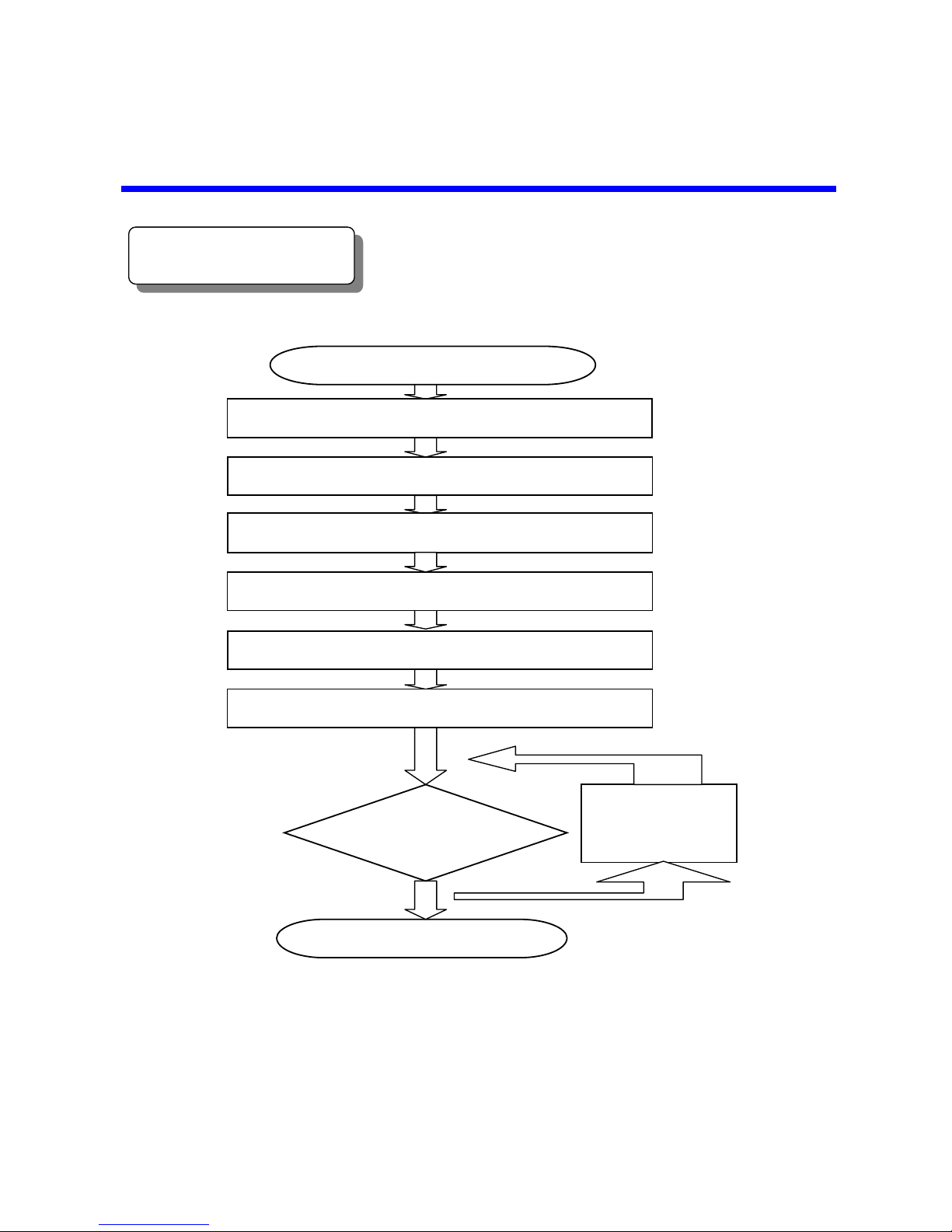
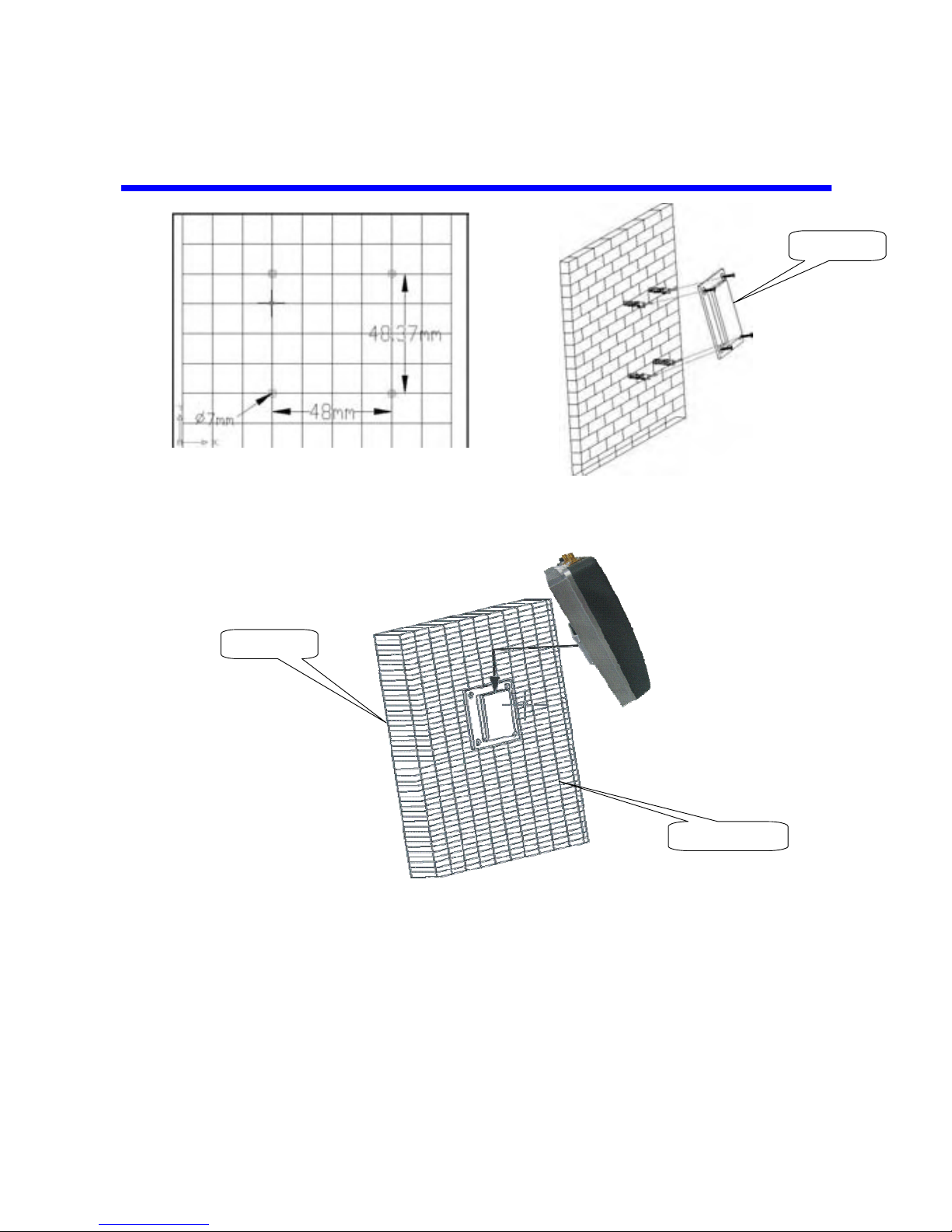
Identify a suitable location where you would like mou
Identify a suitable location where you would like mouIdentify a suitable location where you would like mou
Identify a suitable location where you would like mount
ntnt
nt
the
thethe
the indoor
indoorindoor
indoor
repeater
repeaterrepeater
repeater
Ensure the location is properly isolated from the donor antenna and the
Ensure the location is properly isolated from the donor antenna and theEnsure the location is properly isolated from the donor antenna and the
Ensure the location is properly isolated from the donor antenna and the
cable length supplied is sufficient.
cable length supplied is sufficient.cable length supplied is sufficient.
cable length supplied is sufficient.
Locate a suitable location for the outdoor donor antenna and identify a
Locate a suitable location for the outdoor donor antenna and identify aLocate a suitable location for the outdoor donor antenna and identify a
Locate a suitable location for the outdoor donor antenna and identify a
route for the feeding cable.
route for the feeding cable.route for the feeding cable.
route for the feeding cable.
Measurement of Re
Measurement of ReMeasurement of Re
Measurement of Receiving Level from Base Station
ceiving Level from Base Stationceiving Level from Base Station
ceiving Level from Base Station
(For trained
personnel)
1) Connect feeding cable, which has been connected to the outdoor antenna for
base station, with input of spectrum analyzer.
2) Set measurement environment of Frequency, Span, BW and Amplitude, etc of
the spectrum analyzer.
3) Verify Channel Power value of input signal.
Receiving level is: -
---
45
4545
45dBm ~
dBm ~dBm ~
dBm ~ -
---
40
4040
40dBm
dBmdBm
dBm
Perfect
PerfectPerfect
Perfect
-
---46
4646
46dBm ~
dBm ~dBm ~
dBm ~ -
---
55
5555
55dBm
dBmdBm
dBm
Good
GoodGood
Good
-
---56
5656
56dBm ~
dBm ~dBm ~
dBm ~ -
---
65
6565
65dBm
dBmdBm
dBm
Genera
GeneraGenera
General
ll
l
-
---66
6666
66dBm ~
dBm ~dBm ~
dBm ~ -
---
90
9090
90dBm
dBmdBm
dBm
Acceptable
AcceptableAcceptable
Acceptable
-
---91
9191
91dBm ~
dBm ~dBm ~
dBm ~ -
---
100
100100
100dBm
dBmdBm
dBm
Bad
BadBad
Bad
Notes:
Notes:Notes:
Notes:
a)
a)a)
a) If
IfIf
If
the
thethe
the receiving
receivingreceiving
receiving
power is 1~5dB higher than the perfect power level
power is 1~5dB higher than the per fect power levelpower is 1~5dB higher than the per fect power level
power is 1~5dB higher than the per fect power level,
,,
,
Alarm
AlarmAlarm
Alarm
LED for
LED forLED for
LED for
relevant system turns orange, but the repeater still works
relevant system turns orange, but the repeater still worksrelevant system turns orange, but the repeater still works
relevant system turns orange, but the repeater still works
quite well,
quite well,quite well,
quite well,
and you don
and y ou donand y ou don
and y ou don’
’’’t need to adjust the repeater gain
t need to adjust the repeater gaint need to adjust the repeater gain
t need to adjust the repeater gain
b)
b)
b)
b) If the
If theIf the
If the receiving
receivingreceiving
receiving
power
powerpower
power
is 5~12dB higher than the perfect power level
is 5~12dB higher than the perfect power levelis 5~12dB higher than the perfect power level
is 5~12dB higher than the perfect power level,
,,
,
Alarm
AlarmAlarm
Alarm
LED for relevant system turns red, which means the
LED for relevant system turns red, which means theLED for relevant system turns red, which means the
LED for relevant system turns red, which means the receiving
receivingreceiving
receiving
power level is too strong, or the repeater system self oscillates
power level is too strong, or the repeater system self oscillatespower level is too strong, or the repeater system self oscillates
power level is too strong, or the repeater system self oscillates
due to
due todue to
due to
not enough isolation between donor and server
not enough isolation between donor and servernot enough isolation between donor and server
not enough isolation between donor and server antennas
antennasantennas
antennas, in this case,
, in this case,, in this case,
, in this case,
repeater gain shall be attenuated by DIP Switches or distance shall be
repeater gain shall be attenuated by DIP Switches or distance shall berepeater gain shall be attenuated by DIP Switches or distance shall be
repeater gain shall be attenuated by DIP Switches or distance shall be
enlarged between donor or server antennas.
enlarged between donor or server antennas.enlarged between donor or server antennas.
enlarged between donor or server antennas.