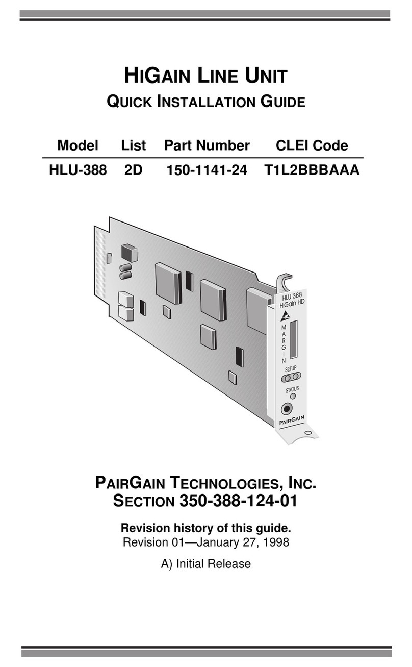
PairGain HTC-439 User manual

HIGAIN TEST CARD
PAIRGAIN TECHNOLOGIES, INC.
ENGINEERING SERVICES TECHNICAL PRACTICE
SECTION 150-101-100-02
Model List Number Part Number CLEI Code
HTC-439 1 150-1559-01 T1DQAB1J

150-101-100-02, Revision 02
ii June 8, 1999 HTC-439 List 1
Revision History of This Practice
©Copyright 1999 PairGain Technologies, Inc.
PairGain and HiGain are registered trademarks of PairGain Technologies, Inc.
Information containedin thisdocumentis company privateto PairGain Technologies,Inc.,
and shall not be modified, used, copied, reproduced or disclosed in whole or in part without
the written consent of PairGain.
Other product names mentioned in this practice are used for identification purposes only
and may be trademarks or registered trademarks of their respective companies.
Revision Release Date Revisions Made
01 November 10, 1997 Initial Release
02 June 8, 1999 Reversed Tip and Ring pin assignments

150-101-100-02, Revision 02 Using This Technical Practice
HTC-439 List 1 June 8, 1999 iii
USING THIS TECHNICAL PRACTICE
Two types of messages, identified by icons, appear in the text.
DOCUMENTATION
If you have comments on this PairGain document, send an email to
technical_publications@pairgain.com. Type the product name and the
section number of the document in the subject area of the email message.
INSPECTING THE SHIPMENT
Upon receipt of the equipment:
•Unpack each container and visually inspect the contents for signs of
damage. If the equipment has been damaged in transit, immediately
report the extent of damage to the transportation company and to
PairGain. Order replacement equipment, if necessary.
•Check the packing list to ensure complete and accurate shipment of each
listed item. If the shipment is short or irregular, contact PairGain as
described inthe Warranty located inside the backcover. If you must store
the equipment for a prolonged period, store the equipment in its original
container.
Notes contain information about special circumstances.
Cautions indicate the possibility of equipment damage or
the possibility of personal injury.

Table of Contents 150-101-100-02, Revision 02
iv June 8, 1999 HTC-439 List 1
TABLE OF CONTENTS
Overview________________________________________________1
Features ....................................................................................1
Test Card ..................................................................................2
Installation ______________________________________________3
Testing a Circuit__________________________________________3
Appendix A - Specifications ________________________________6
Appendix B - Glossary_____________________________________7
Appendix C - Product Support______________________________8
Technical Support.....................................................................8
World Wide Web......................................................................8
Returns......................................................................................9
Certification and Warranty __________________Inside Back Cover
LIST OF FIGURES
Figure 1. HTC-439 List 1 Test Card.......................................................2
Figure 2. HTC-439 List 1 Test Connections...........................................5
LIST OF TABLES
Table 1. Test Connections ......................................................................4

150-101-100-02, Revision 02 Overview
HTC-439 List 1 June 8, 1999 1
OVERVIEW
This practice describes the PairGainHiGainTest Card HTC-439 List 1.
The HTC-439 provides a convenient method of testing Central Office (CO)
and Field Tip and Ring transmit and receive pairs from any standard T1-239
repeater slot.
FEATURES
•Four-position slider switch (S1) that allows you to select the kind of test
you wish to perform on the transmit (XMT) and receive (RCV) Tip and
Ring pairs on CO and field circuits:
–Open
–Short
–Loop Thru
–Loop Back (metallic)
•Test points that provide access to Tip and Ring circuits (CO and field)
and to frame ground.
•Miniature210jacks locatedwithinthe J1block thatprovide accesstoCO
and field Tip and Ring circuit sides.
•Designed to extend beyond the front plane of the shelf or enclosure into
which the HTC-439 is inserted to permit easy access to its test points.

Overview 150-101-100-02, Revision 02
2 June 8, 1999 HTC-439 List 1
TEST CARD
Test points on the HTC-439 (Figure 1) provide access to each circuit under
test as well as to frame ground. The four-position test slider switch (S1)
selects which test (Open, Short,Loop Thru, or Loop Back) is to be performed
on CO and field circuits. The Open switch position effectively provides a
splitting-type access to one pair of the CO and field sides and the 210 jacks.
The Loop Back or Loop Thru switch positions allow you to use the two
miniature 210 jacks located within the J1 block. All tests are run on both side
1 and side 2. Refer to “Testing a Circuit” on page 3 for further information.
Figure 1. HTC-439 List 1 Test Card
CO
SIDE 1
SIDE 1
T
T
R
R
TP5
TP6
TP9
TP8
CO
CO
TP3
TP4
TP12
TP11 TP1
FIELD
FIELD
OPEN
SHORT
LOOP THRU
LOOP BACK
FIELD
SIDE 2
SIDE 2
PairGain
S1 switch
S1 switch
positions Circuit schematic
Conector pins
1
1
2
Miniature
210 jacks
Test points

150-101-100-02, Revision 02 Installation
HTC-439 List 1 June 8, 1999 3
INSTALLATION
1Insert the HTC-439 into the shelf slot for the channel you want to test.
2Push the card all the way into the slot until the card is firmly seated.
TESTING ACIRCUIT
Use the HTC-439 to test circuits, as follows:
1Set the slider switch S1 to the type of test you want to perform (Open,
Short, Loop Thru, or Loop Back).
2Connect to test points as applicable. The connections of Tip and Ring
pairs of CO and field circuits for each setting of the switch are listed in
Table 1 on page 4 and illustrated in Figure 2 on page 5. (Pin numbers
correspond to the edge connector pins for each circuit.)
3Perform the selected test.
4Monitor the circuits at the corresponding test points on the card.
5Repeat steps 1 through 4 as required.
All wiringexternal to the productshould followthe provisions
of the current edition of the National Electrical Code.

Testing a Circuit 150-101-100-02, Revision 02
4 June 8, 1999 HTC-439 List 1
Table 1. Test Connections
Connect Pin Number To Pin Number
Loopback - This switch position connects the following circuits
CO Tip 6CO Tip 9
CO Ring 5CO Ring 8
Field Tip 4Field Tip 12
Field Ring 3Field Ring 11
Loopthru - This switch position connects the following circuits
CO Tip 6Field Tip 4
CO Ring 5Field Ring 3
CO Tip 9Field Tip 12
CO Ring 8Field Ring 11
Short - This switch position connects the following circuits
CO Tip 6CO Ring 5
CO Tip 9CO Ring 8
Field Tip 4Field Ring 3
Field Tip 12 Field Ring 11
Open - This switch position removes all connections between the circuits

150-101-100-02, Revision 02 Testing a Circuit
HTC-439 List 1 June 8, 1999 5
Figure 2. HTC-439 List 1 Test Connections
CO
SIDE 1
SIDE 1
T
T
R
R
TP5
TP6
TP9
TP8
CO
CO
TP3
TP4
TP12
TP11 TP1
FIELD
FIELD
OPEN
SHORT
LOOP THRU
LOOP BACK
FIELD
SIDE 2
SIDE 2
PairGain
To/From
CO Equipment
TP1
Test point 6
(TP6)
LOOP THRU TIP
TIP
RING
RING
SIDE 1
SIDE 2
6
9
5
8
TIP
TIP
RING
RING
4
3
12
11
SHORT TIP
TIP
RING
RING
SIDE 1
SIDE 2
6
9
5
8
TIP
TIP
RING
RING
4
3
12
11
OPEN TIP
TIP
RING
RING
SIDE 1
SIDE 2
6
9
5
8
TIP
TIP
RING
RING
4
3
12
11
To/From
Field
Equipment
1
10
FRAME GND
FRAME GND
LOOP BACK TIP
TIP
RING
RING
SIDE 1
SIDE 2
TIP
TIP
RING
RING
9
5
8
4
3
12
11
TP6 TP4
TP5 TP3
TP9 TP12
TP8 TP11
6

Appendix A - Specifications 150-101-100-02, Revision 02
6 June 8, 1999 HTC-439 List 1
APPENDIX A - SPECIFICATIONS
Mounting Any T1-239 repeater mechanics slot
Environmental
Operating Temperature: 40 °F to + 149 °F (-40 °C to + 65 °C)
Operating Humidity: 5% to 95% (non condensing)
Dimensions and Weight
Height: 3.1 in. (7.87 cm)
Width: 0.6 in. (1.52 cm)
Depth: 8.4 in. (21.34 cm)
Weight: 0.30 lb. (0.66 kg)

150-101-100-02, Revision 02 Appendix B - Glossary
HTC-439 List 1 June 8, 1999 7
APPENDIX B - GLOSSARY
CO Central Office
GND Ground
HTC HiGain Test Card
RCV Receive
RMA Return Material Authorization
XMT Transmit

Appendix C - Product Support 150-101-100-02, Revision 02
8 June 8, 1999 HTC-439 List 1
APPENDIX C - PRODUCT SUPPORT
PairGain Customer Service Group provides expert pre-sales and post-sales
support and training for all its products.
TECHNICAL SUPPORT
Technical assistance is available 24 hours a day, 7 days a week by contacting
PairGain Customer Service Group at:
During normal business hours (7:30 AM to 5:30 PM, Pacific Time, Monday
through Friday, excluding holidays), technical assistance calls are normally
answered directly by a Customer Service Engineer. At other times, a request
for technical assistance is handled by an on-duty Customer Service Engineer
through a callback process. This process normally results in a callback within
30 minutes of initiating the request.
WORLD WIDE WEB
PairGain product and company information can be found at
http://www.pairgain.com using any Web browser.
Telephone: (800) 638-0031 or (714) 832-9922
The 800 telephone support line is toll-free in the
U.S. and Canada.
Fax: (714) 832-9924
Email: support@pairgain.com

150-101-100-02, Revision 02 Appendix C - Product Support
HTC-439 List 1 June 8, 1999 9
RETURNS
To return equipment to PairGain:
1Locate the number of the purchase order under which the equipment was
purchased. You will need to provide this number to PairGain Customer
Service to obtain a return authorization.
2Call or write PairGain Customer Service to ask for a Return Material
Authorization (RMA) number and any additional instructions. Use the
telephone or fax number listed below:
•Telephone: (800) 370-9670
•Fax: (714) 730-2961
3Include the following information, in writing, along with the equipment
you are returning:
•Company name, address, and the name of a person PairGain can
contact regarding this equipment.
•The purchase order number provided to Customer Service when the
RMA number was requested.
•A description of the equipment, as well as the number of units that
you are returning. Be sure to include the model and part number of
each unit.
•The shipping address to which PairGain should return the repaired
equipment.
•The reason for the return, for example:
The equipment needs an ECO/ECN upgrade.
The equipment is defective.
If the equipment is defective, please tell us what you
observed just before the equipment malfunctioned. Be as
detailed in your description as possible.

Appendix C - Product Support 150-101-100-02, Revision 02
10 June 8, 1999 HTC-439 List 1
4Pack the equipment in a shipping carton.
5Write PairGain’s address and the Return Material Authorization number
you received from Customer Service clearly on the outside of the carton:
PairGain Technologies, Inc.
14352 Franklin Ave.
Tustin, CA 92780-7013
Attention: CRF RMA (Number)

CERTIFICATION AND WARRANTY
FCC COMPLIANCE
The HTC-439 List 1doesnot have any clockingsource, and deems to be a passive deviceper FCC
guidelines. When used in conjunction with any clocking devices, this combined system may radiate
radio frequency energythatcancauseharmful interference toradio communications.Operation of
such asystem in a residential area is likely tocauseharmful interference,inwhich case the user will
be required to correct the interference at his own expense.
WARRANTY
PairGain Technologies warrants this productto be free of defects and to be fully functional for a period
of 60 monthsfrom the date oforiginal shipment, given correct customer installation and regular
maintenance.PairGainwillrepair or replaceatPairGain’s option any unitwithoutcostduring this
period if the unit is found to be defective for any reason other than abuse or incorrect use or installation.
Do not try to repair the unit.Ifit fails,replace it with another unit and return the faulty unit to PairGain
for repair.Any modifications ofthe unit by anyone other than anauthorizedPairGain representative
voids the warranty.
If aunitneeds repair, callPairGain for a Return Material Authorization (RMA) number and return the
defective unit, freight prepaid, along with a brief description of the problem, to:
PairGain Technologies, Inc.
14352 Franklin Avenue
Tustin, CA 92780
ATTN: Repair and Return Dept.
(800) 638-0031
Refer to the instructions under “World Wide Web” on page 8 for complete return instructions.
PairGain continuestorepair faultymodulesbeyondthewarranty program at a nominalcharge.Contact
your PairGain sales representative for details and pricing.
MODIFICATIONS
Any changes ormodifications made to this device that are not expressly approved by PairGain
Technologies, Inc. may void the user's warranty.
All wiring external to the products should follow the provisions of the current edition of the National
ElectricalCode.
For technical assistance, refer to “TechnicalSupport”onpage8.

Corporate Office
14402 Franklin Avenue
Tustin, CA 92780
Tel: (714) 832-9922
Fax: (714) 832-9924
For Technical Assistance:
(800) 638-0031
This manual suits for next models
1
Table of contents
Other PairGain Computer Hardware manuals