PairGain HLU-231 User manual

HIGAIN LINE UNIT
PAIRGAIN TECHNOLOGIES, INC.
ENGINEERING SERVICES TECHNICAL PRACTICE
™150-231-175-01T¨
SECTION 150-231-175-01
Model List Number Part Number CLEI Code
HLU-231 7E 150-1111-75 T1L2KSXAAA
R
S
2
3
2
L
MARGIN
STATUS
BRG
SPAN
XMT
RCV
BRG
SPAN
dB
HLU 231
H G LINE UNIT
IAIN
HDSL
MODE
D
S
1
SEL
PairGain

Revision History of This Practice 150-231-175-01, Revision 01
ii September 23, 1998 HLU-231 List 7E
REVISION HISTORY OF THIS PRACTICE
©Copyright 1998 PairGain Technologies, Inc.
PairGain and HiGain are registered trademarks of PairGain Technologies, Inc.
Information contained in this document is company private to PairGain Technologies, Inc., and shall not be modified, used, copied,
reproduced or disclosed in whole or in part without the written consent of PairGain.
Other product names mentioned in this practice are used for identification purposes only and may be trademarks or registered
trademarks of their respective companies.
Revision Release Date Revisions Made
01 September 23, 1998 Initial release

150-231-175-01, Revision 01 Using This Technical Practice
HLU-231 List 7E September 23, 1998 iii
USING THIS TECHNICAL PRACTICE
Two types of messages, identified by icons, appear in the text.
INSPECTING SHIPMENT
Upon receipt of the equipment:
•Unpack each container and visually inspect it for signs of damage. If the equipment has been damaged in
transit, immediately report the extent of damage to the transportation company and to PairGain. Order
replacement equipment, if necessary.
•Check the packing list to ensure complete and accurate shipment of each listed item. If the shipment is short
or irregular, contact PairGain as described in the Warranty. If you must store the equipment for a prolonged
period, store the equipment in its original container.
Notes contain information about special circumstances.
Cautions indicate the possibility of equipment damage or the possibility of personal injury.

Inspecting Shipment 150-231-175-01, Revision 01
iv September 23, 1998 HLU-231 List 7E

150-231-175-01, Revision 01 Table of Contents
HLU-231 List 7E September 23, 1998 v
TABLE OF CONTENTS
Overview ____________________________________________________________________________ 1
Features..............................................................................................................................................1
Applications .......................................................................................................................................2
Applications without HiGain Doublers...............................................................................2
Applications with HiGain Doublers ....................................................................................3
Product Description............................................................................................................................3
Front Panel...........................................................................................................................4
Status LED...........................................................................................................................5
Front Panel Display .............................................................................................................5
HLU-231 List 7E Card Connector.......................................................................................7
Network Management Control Bus.....................................................................................8
Fuse Alarm ..........................................................................................................................8
System Alarm Relay Output................................................................................................8
Installation___________________________________________________________________________ 9
Provisioning the HLU-231______________________________________________________________ 9
Setting Options through SEL and MODE........................................................................................10
Factory Default Values......................................................................................................10
Displaying System Inventory ............................................................................................11
Connecting to a Maintenance Terminal...........................................................................................11
Maintenance ________________________________________________________________________ 12
Navigating the Maintenance Terminal Screens ...............................................................................12
System Spans.....................................................................................................................12
Navigation Keys ................................................................................................................13
Selecting an Option ...........................................................................................................13
Initializing the Maintenance Terminal Screens ...............................................................................13
Maintenance Terminal Main Menu..................................................................................................14
View Span Status .............................................................................................................................15
Span Status Screen: Non-Doubler Applications................................................................15
Span Status Screen: Doubler Applications........................................................................15
Span Status Fields, Alarms, and Loopbacks......................................................................17
Set Clock..........................................................................................................................................19
Set Time.............................................................................................................................19
Set Date..............................................................................................................................20
Update the HRU Time and Date........................................................................................20

Table of Contents 150-231-175-01, Revision 01
vi September 23, 1998 HLU-231 List 7E
System Settings ............................................................................................................................... 20
DS0 Blocking Option........................................................................................................ 21
DS1 Line Code Option...................................................................................................... 21
Margin Alarm Threshold .................................................................................................. 22
HAIS Selections................................................................................................................ 22
HDSL Line Voltage Operation ......................................................................................... 22
Ground Fault Detect.......................................................................................................... 23
System Settings Screen Options ....................................................................................... 23
Loopback Menu............................................................................................................................... 25
Loopback Menu: No Doubler........................................................................................... 26
Loopback Menu: Two Doublers ....................................................................................... 26
Initiating a Loopback........................................................................................................ 27
Disable Loopbacks............................................................................................................ 27
Performance Data Screens............................................................................................................... 28
Performance Data Screen: No Doubler............................................................................. 29
Performance Data Screen: With Doubler.......................................................................... 29
View Performance History.............................................................................................................. 30
The 7 Day History Screen: No Doubler............................................................................ 31
The 7 Day History Screen: With Doubler......................................................................... 31
View Alarm History ........................................................................................................................ 32
Alarm History Screen: No Doubler .................................................................................. 33
Alarm History Screen: With Doubler ............................................................................... 34
Circuit ID......................................................................................................................................... 34
System Alarms_______________________________________________________________________ 35
Retiring System Alarms .................................................................................................................. 35
Self Test........................................................................................................................................... 36
Loopback Operation__________________________________________________________________ 36
SmartJack (SMJK) Loopback.......................................................................................................... 36
Generic Loopback Code (GNLB) ................................................................................................... 36
Addressable Repeater Loopback Functions .................................................................................... 37
Initiating Manual Loopback Sessions .............................................................................................37
Loopback Test Procedures .............................................................................................................. 38
Loopback Operation without Doublers........................................................................................... 39
Loopback Operation with Doublers................................................................................................39
GNLB Loopback Test Procedures...................................................................................................41
A1LB, A2LB, and A5LB Test Procedures ....................................................................... 41
A3LB and A4LB Test Procedures .................................................................................... 44

150-231-175-01, Revision 01 Table of Contents
HLU-231 List 7E September 23, 1998 vii
Appendix A - Technical Specifications___________________________________________________ 46
Appendix B - Abbreviations ___________________________________________________________ 47
Appendix C - Functional Operation_____________________________________________________ 49
Power Consumption.........................................................................................................................50
Power Consumption: Without Doublers............................................................................50
Maximum Power Dissipation:.............................................................................50
Maximum Power Consumption: .........................................................................50
Maximum Current Drain:....................................................................................50
Power Consumption: With Doublers.................................................................................51
Appendix D - Compatibility ___________________________________________________________ 53
T1 Repeater Shelves and Related Equipment..................................................................................53
HiGain Doubler Circuit Deployment...............................................................................................53
Appendix E - Product Support _________________________________________________________ 55
Technical Support............................................................................................................................55
Warranty...........................................................................................................................................55
FCC Compliance..............................................................................................................................56
Modifications ...................................................................................................................................56
Standards Compliance......................................................................................................................56
Barcode and Configuration Number Information............................................................................57

List of Figures 150-231-175-01, Revision 01
viii September 23, 1998 HLU-231 List 7E
LIST OF FIGURES
Figure 1. HLU-231 List 7E Front Panel .......................................................................................................... 4
Figure 2. HLU-231 List 7E Card-Edge Connector.......................................................................................... 7
Figure 3. Installing the HLU-231 into a Shelf................................................................................................. 9
Figure 4. DB-9 RS-232 I/O Pinouts............................................................................................................... 12
Figure 5. System Spans.................................................................................................................................. 13
Figure 6. Maintenance Terminal Main Menu................................................................................................ 14
Figure 7. Span Status Screen (No Doubler)................................................................................................... 15
Figure 8. Span 1 Status Screen ...................................................................................................................... 16
Figure 9. Span 2 Status Screen ...................................................................................................................... 16
Figure 10. Set Clock Screen .......................................................................................................................... 19
Figure 11. System Settings Screen ................................................................................................................ 20
Figure 12. Loopback Menu: No Doubler....................................................................................................... 26
Figure 13. Loopback Menu with Two Doublers............................................................................................ 26
Figure 14. NLOC Loopback Mode in the Maintenance Terminal Main Menu............................................. 27
Figure 15. Performance Data Screen: No Doublers....................................................................................... 29
Figure 16. Span 3 Performance Data Screen................................................................................................. 30
Figure 17. 7 Day History Screen for Span 1 (No Doubler)........................................................................... 31
Figure 18. 7 Day History Screen Span 3 ....................................................................................................... 32
Figure 19. Alarm History Screen for Span 1 ................................................................................................. 33
Figure 20. Alarm History Screen for Span 3 ................................................................................................. 34
Figure 21. HLU-231 Non-Doubler Loopback Configurations...................................................................... 39
Figure 22. Doubler Loopback Configurations............................................................................................... 40
Figure 23. HLU-231 Block Diagram............................................................................................................. 49
Figure 24. Bar Code Label and Configuration Number ................................................................................ 57

150-231-175-01, Revision 01 List of Tables
HLU-231 List 7E September 23, 1998 ix
LIST OF TABLES
Table 1. HDSL Loss Over Cables....................................................................................................................2
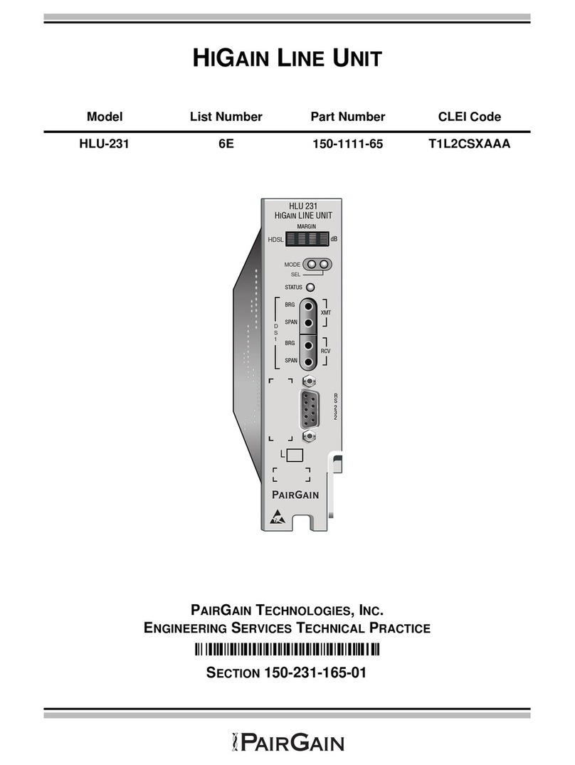
Table 2. Front Panel Components and Labels..................................................................................................5
Table 3. Status LED Descriptions ....................................................................................................................5
Table 4. Front Panel Display Messages .........................................................................................................6
Table 5. Navigational Keys on the Maintenance Terminal............................................................................13
Table 6. Maintenance Terminal Screens ........................................................................................................14
Table 7. Span Status Fields and Descriptions ...............................................................................................17
Table 8. HLU-231 Status Menu Messages ....................................................................................................18
Table 9. HLU-231 List 7E System Settings Screen Options .........................................................................23
Table 10. Errored and Unavailable Seconds Definitions ...............................................................................28
Table 11. Alarm History Fields and Descriptions..........................................................................................33
Table 12. HDSL System Alarms....................................................................................................................35
Table 13. SPLB Loopback Command Set......................................................................................................40
Table 14. Addressable 1, 2, 5 (A1LB, A2LB, A5LB) Repeater Loopback Commands................................44
Table 15. Addressable 3 and 4 (A3LB and A4LB) Repeater Loopback Commands.....................................45
Table 16. HLU-231 List 7E Power Parameters with HDU-451 Doublers, List 1, 2, 3, & 4, and M/M.........52
Table 17. HLU-231 List 7E/HDU-451 List 1, 2, & 3 Deployment Guidelines .............................................52
Table 18. HiGain Doubler Deployment Matrix ............................................................................................54
Table 19. Bar Code Label and Configuration Number Descriptions.............................................................57

List of Tables 150-231-175-01, Revision 01
x September 23, 1998 HLU-231 List 7E

150-231-175-01, Revision 01 Overview
HLU-231 List 7E September 23, 1998 1
OVERVIEW
The PairGain®HiGain®HLU-231 List 7E is the Central Office (CO) side of a repeaterless, T1 transmission
system. When used in conjunction with a remote unit or HRU, the system provides 1.544 Mbps transmission on
two unconditioned copper pairs over the full Carrier Service Area (CSA) range. This line unit can be used in
applications with or without HDUs.
The CSA includes loops up to 12,000feet of 24 AWG or 9,000 feet of 26 AWG wire, including bridged taps.The
HiGain system uses HDSL transmission technology as recommended by Bellcore TA-TSY-001210. The HiGain
system complies with GR-63 CORE, TR-TSY-000499 and GR1089 CORE.
FEATURES
•Selectable DSX-1 Pre-equalizer
•140 V to 200 V self-adjusting line voltage for HRU and HDU-451 applications
•Front Panel HDSL S/N Margin Display
•Selectable Loopback activation codes
•RS-232 maintenance port
•Front-panel user option setup
•Front Panel DSX-1 splitting & bridging access
•Lightning and power cross protection on HDSL interfaces
•kbps full-duplex 2B1Q HDSL Transmission on two pairs
•Front panel status indicating LED
•Automatic front-panel display blanking
•Margin threshold alarm
•HAIS & SAIS options
•Easy default setting of user options
•New T1 transceiver chip
•Circuit ID option
•Network management ready
•Single board design
•Can line power 3 spans (2 doublers and 1 remote).

Overview 150-231-175-01, Revision 01
2 September 23, 1998 HLU-231 List 7E
APPLICATIONS
The HiGain system provides a cost-effective, easy to deploy method for delivering T1 High Capacity Digital
Service (HCDS) over metallic pairs:
•The service is deployed over two unconditioned, non-loaded copper pairs, yet it demonstrates a quality that
is competitive with fiber optics.
•Conventional in-line T1 repeaters are not required.
•Cable pair conditioning, pair separation and bridged tap removal, are not required.
Each loop has no more than 35 dB of loss at 196 kHz, with driving and terminating impedances of 135Ω. Table 1
provides a “loss” guide for the various cable gauges at 196 kHz and 135Ω. The table applies to the HDSL cable
pairsbetween the HLU, HRU, and HDU modules. In the absence of specific insertion loss measurement data, add
3 dB for each bridged tap and 1 dB for each cable gauge change.
The HiGain system operates with any number of other T1, POTS, Digital Data Service (DDS) or other HiGain
systems sharing the same cable binder group. HiGain systems can be used with customers requiring DS1 service
on a temporary or permanent basis. The HiGain system also provides a means of quickly deploying service in
advance of fiber-optictransmission systems. With theHiGain system, service can beprovided within hours. Fiber
optic systems can be installed at a leisurely pace and cut-over from the installed HiGain system when convenient
to do so. The installed HiGain system can then be easily removed and utilized elsewhere.
In general, HiGain systems:
•operate with any number of other T1,POTS, Digital Data Service (DDS) or other HiGain systems sharing the
same cable binder group
•can be used with customers requiring DS1 service on a temporary or permanent basis
•provide a means of quickly deploying service in advance of fiber-optic transmission systems.
With a HiGain system, service can be provided within hours. Fiber-optic systems can be installed incrementally
and cut-over from the installed HiGain system when convenient to do so.
Applications without HiGain Doublers
This section addresses HLU-231 List 7E operation when used without doublers. For applications without
doublers, the HLU-231 is directly connected to the HRU by the two HDSL cable pairs. The HLU-231 is
compatible with all HiGain HRUs.
Table 1. HDSL Loss Over Cables
Cable Gauge Loss at 196 kHz (db/kft) Ohms per kft
26/0.4mm 3.88 83
24/0.51mm 2.84 52
22/0.61mm 2.18 32
19/0.91mm 1.54 16

150-231-175-01, Revision 01 Overview
HLU-231 List 7E September 23, 1998 3
Applications with HiGain Doublers
For Doubler applications, one or two Doublers may be used in theHDSL loops between theHLU-231 List 7E and
the HRU:
The HLU-231 can line power one doubler and the remote unit for a total of two spans.
If the remote unit is locally powered, the HLU-231 can power up to two doublers for a total of three spans.
The HLU-231, List 7E has been enhanced over the older HiGain line units so that it can line power two doublers
and the remote unit (three spans). This feature is only available when using the HDU-439, 437 List 1 “mini”
doublers and the HRU-412 List 8 remote unit in HDU-231, List 7E circuits.
For additional information on the “mini” doublers refer to technical practice #150-439-100-01. This section
addresses HLU-231 List 7E operation with the HDU-451 List 1, 2, 3, & 4 or the HDU-439, 437 “mini” doublers.
The List 1 and 2 doublers have identical power consumptions.The List 3 and4 units are low power doublers which
consumes 40% less power than either List 1 or 2. The Power Consumption section addresses both the high and
low power doubler versions.
PRODUCT DESCRIPTION
The HLU-231 includes:
•A front panel featuring:
–A status display
–System option buttons
–Status LED
–DSX-1 access jacks
–RS-232 Craft port
–CLEI/ECI bar code number
–Configuration number
•Card-edge connector

150-231-175-01, Revision 01 Overview
HLU-231 List 7E September 23, 1998 5
Status LED
Table 3 describes the functions of the Status LED on the front panel.
Front Panel Display
The front panel display is used with the MODE and SEL buttons to display system diagnostic messages. Refer to
Table 4 for a listing of the four character messages.
The front panel display turns on when power is initially applied to the HLU-231. To conserve power, the display
only remains on for 4minutes. The use of the MODE or SEL buttons activates thefront panel display and restarts
the 4-minute, power-control timer.
Table 2. Front Panel Components and Labels
Front Panel Feature Function
Front panel display Displays four-character status, provisioning, and alarm system messages.
System option buttons
(MODE and SEL)
Permits the user options to be monitored and modified without the need of a maintenance
terminal. Used to initiate all HiGain loopbacks and to display DSX-1 line parameters and line unit
identity.
Status LED See Table 3 for status descriptions.
DSX-1 access jacks
SPAN Provides splitting jack access to (XMT) and from (RCV), the HDSL span at the DSX-1 interface.
Breaks the XMT and RCV paths to permit test signal insertion and retrieval.
BRIDGE Provides non-intrusive bridging jack access to (XMT) and from (RCV) the HDSL span at the DSX-1
interface. Allows the two T1 payloads to be monitored.
Craft (RS-232) port Provides bidirectional communication between the unit and an external terminal to allow
configuration and performance monitoring through the Maintenance Terminal screens.
CLEI/ECI bar code label Provides the human-readable Common Language Equipment Identifier (CLEI) code number and
the Equipment Catalog Item (ECI) bar code number.
Configuration Number The configuration number is a two or three-digit number that is either the last digits of a 5 or 6-digit
warranty control number or is a standalone number of two or three digits. For example, a warranty
control number of “80107” would indicate a warranty beginning in the year 1998 (8), during the
month of January (01), and the unit’s configuration number of 7 (07).
Table 3. Status LED Descriptions
LED Status Description
Green Normal operation
Flashing green HDSL acquisition
Red Fuse Alarm
Flashing red System alarm
Yellow Self Test is in process or an HLU-231 List 7E Customer Remote
Loopback (CREM) or a Network Local Loopback (NLOC) is in effect.
Flashing yellow HLU-231 is in an Armed state

Overview 150-231-175-01, Revision 01
6 September 23, 1998 HLU-231 List 7E
Table 4. Front Panel Display Messages
Message Full Name Description
CREM Customer Remote Loopback Signal from customer is looped back to customer at HLU-231.
NLOC Network Local Loopback DSX signal is looped back to DSX at HLU.
CLOC Customer Local Loopback Signal from Customer is looped back to customer at HRU.
NREM Network Remote Loopback DSX signal is looped back to DSX at HRU.
SMJK Remote Smartjack Loopback Signal from DSX is looped back at HRU by the HRU smartjack module.
TLOS Transmit Loss Of Signal HRU is in a logic loopback state caused by a loss of its T1 input from the
CI, if enabled at the HRU via its TLOS switch option.
FERR Framing Bit Error Occurred Framing bit error occurred at HLU T1 input.
LBPV Local Bipolar Violation A bipolar violation has been received at the T1 input to the HLU-231.
SIG 1 or 2 Signal 1 or Signal 2 The HLU & HRU transceivers are trying to establish contact with each
other.
ACQ 1 or 2 Acquisition 1 or Acquisition 2 The HLU & HRU multiplexers are trying to establish synchronization over
each loop.
H1ES HDSL CRC Error Channel 1 HLU HDSL Loop 1 CRC error.
H2ES HDSL CRC Error Channel 2 HLU HDSL Loop 2 CRC error.
ARM HiGain System ARMED Armed to respond to Intelligent Repeater Loop Codes.
ACO Alarm CutOff A minor alarm has occurred, and been retired to an ACO condition, by
pressing the SEL button on the HLU front panel.
SELF TEST Self Test The HLU is in a self test mode. This occurs every power ON/OFF cycle.
ALRM Alarm Condition Exists A minor alarm condition is in effect.
1=xx or 2=yy HDSL Loop Margins Indicates the power of the received HDSL signal on each Loop relative to
noise. Any value of ‘06’ or greater is adequate for reliable system operation.
PWR FEED SHRT Power Feed Short Indicates a short between the 2 HDSL pairs. This same message can occur
with an HRU that is drawing the correct amount of power over good cable
pairs but cannot communicate with the HLU.
PWR FEED OPEN Power Feed Open Indicates an open circuit in the T&R of either HDSL pair.
PWR FEED OFF Power Feed Off HDSL span power has been turned off by setting the PWFD option to DIS.
BAD RT? No response from HRU The HLU does not receive any response from the HRU. Thus, the integrity
of the HRU or the two HDSL loops (they may be open) is questionable.
VER HLU Software Version # This is displayed during the System Settings review mode. Depress the
MODE button for 3 seconds.
LIST 0xL HLU’s List # Displayed during System Settings review mode defined above.
FRM Frame: SF,ESF,UNFR,NONE Defines the type of frame pattern being received from the DSX-1. Displayed
during System Settings review mode defined above.
CODE Line Code: AMI, B8ZS This is the line code that HLU-231 List 7E is receiving at its DSX-1
interface. Displayed during System Setting review mode defined above.
LOSW Loss of Sync Word Indicates that 1 of the HDSL loops has lost sync. Causes a minor alarm.

150-231-175-01, Revision 01 Overview
HLU-231 List 7E September 23, 1998 7
HLU-231 List 7E Card Connector
Figure 2 shows the card-edge connectors on the HLU-231. Active pins are highlighted in black.
Figure 2. HLU-231 List 7E Card-Edge Connector
LLOS Local Loss of Signal Indicates that no signal is detected at the T1 input to the HLU. Causes a
minor alarm.
RLOS Remote Loss of Signal Indicates that no signal is detected at the T1 input to the HRU. Causes a
minor alarm.
DS1 DS1 BPV errors Indicates that the number of BPVs at the HLU or HRU DS1 inputs have
exceeded the 24 hour ES threshold. Causes a minor alarm.
DS0 DS0 Blocked Channels Indicates status of DS0 blocked channels. NONE indicates no channels are
blocked. BLK indicates some channels are blocked.
MAL1(2) Margin Alarm Loop 1 or 2 The margin on HDSL loop 1 (2) has dropped below the threshold (1 to 15
dB) set by the user.
Table 4. Front Panel Display Messages (Cont.)
Message Full Name Description

Overview 150-231-175-01, Revision 01
8 September 23, 1998 HLU-231 List 7E
Network Management Control Bus
The HLU-231 List 7E provides a Network Management Control Bus on pin 46 of the card-edge connector. This
allows the various PairGain Management System protocols to manage the HLU through the HMU-319 HiGain
Management Unit. Whenever the HLU-231 is under management,the MNGD message displays periodically on the
HLU-231 front panel display.
Fuse Alarm
Pin 32 on the card-edge connector is a Fuse Alarm that is driven to -48V through a 1000Ωresistor whenever the
onboard fuse opens.
System Alarm Relay Output
The normally open alarm contacts available across pins 20 and 21 (Figure 2 on page 7) comprise the HLU-231
system alarm output. These alarm contacts close for any system alarms condition. This alarm contacts also close
if power is lost or removed from the slot, providing fail-safe relay output. See “System Alarms” on page 35 for
further information about system alarms.
Some HLU-231 features are affected when it is under management. Consult the management
unit practice for further information.

150-231-175-01, Revision 01 Installation
HLU-231 List 7E September 23, 1998 9
INSTALLATION
To install the HLU-231:
1Slide the HLU-231 into the card guides for the desired slot, then push the unit back until it touches the
backplane card-edge connector and the retaining latch on the front panel opens (Figure 3).
Figure 3. Installing the HLU-231 into a Shelf
2Place your thumbs on the HLU-231 front panel and push the HLU-231 into the card-edge connector until it
is entirely within the card guides and the retaining latch closes. This indicates that the card is properly seated.
PROVISIONING THE HLU-231
There are two methods for provisioning the HLU-231:
•Use the MODE and SEL buttons on the front panel
•Access system settings screens through the RS-232 Craft port.
No dip switches or jumpers are required to provision the HLU-231 as it contains a non-volatile RAM (NVRAM)
which stores the system option settings. System settings are retained if shelf power is lost or if the HLU-231 is
unplugged.

Provisioning the HLU-231 150-231-175-01, Revision 01
10 September 23, 1998 HLU-231 List 7E
SETTING OPTIONS THROUGH SEL AND MODE
To provision the HLU-231 through the MODE and SEL buttons on the front panel:
1Press the MODE button and release it after 1 second.
Themessagedisplayed onthe front panel alternatesbetween the first system parameter and its current setting.
2Press the SEL button to step the display through all possible settings (one at a time) of the selected parameter.
3After the desired setting has been selected, press the MODE button.
This updates the current displayed mode to the selected setting, and then advances to the next configurable
parameter.
Afterthelastparameterhas been selected,a “Confirm? (Yes/No)”messageappears on the frontpaneldisplay.
4Do one of the following:
•To cancel the session without saving the requested parameter changes, press the MODE button. (Or, do
nothing. After 30 seconds, the display returns to its normal mode without saving the new changes.)
•To accept the requested parameter changes, press the SEL button. (A YES message displays, and the
display returns to its normal mode after saving the new changes.)
In either case the display returns to its normal mode.
Factory Default Values
All user options can be set tothe factory default values using the SEL and MODE buttons. To set the user options
to their default values:
1Press the SEL button for 6 seconds until the following message appears:
DFLT NO
2Press the SEL button while the DFLT NO message is displayed.
The message changes to DFLT YES indicating the factory default values are now in effect.
To terminate the DFLT mode without setting the factory default values, do one of the following:
•Press the MODE button or
•Wait 30 seconds for the display to return to its normal state.
Other manuals for HLU-231
8
This manual suits for next models
1
Table of contents
Other PairGain Computer Hardware manuals