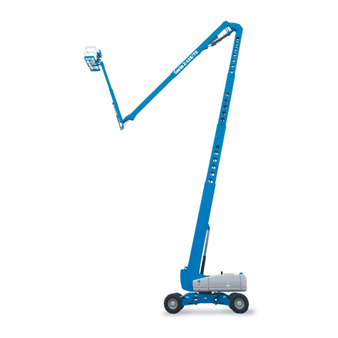
PALAZZANI RAGNO XTJ 43 User manual

PALIFT - DIVISION
RAGNO XTJ 43
USE AND MAINTENANCE MANUAL
RAGNO
SERIES NUMBER
YEAR OF PRODUCTION
MANUAL N°
XTJ 43 / C
PT 3582
2016
NM 665
Original copy

Warning for the users
The contents of this manual are based on know-how, designs, technology applications,
used on exclusive basis by Palazzani Industrie SpA, and therefore protected by national
and international intellectual property.
Any reference to names, dates and addresses of other Companies is not on purpose and,
unless otherwise indicated, it is only an example, to better understand the products made
by Palazzani Industrie SpA
The processing of text and images are evaluated with the utmost care, in any case Pa-
lazzani reserves the right to modify and / or update the information contained herein, to
correct typographical errors and / or inaccuracies, without notice or obligation on the
part thereof.
This manual contains all the information necessary for the operators for the normal and
planned use of Palazzani products.
The content of this manual is purely technical and owned by Palazzani Industrie SpA.
Any part of this manual may be translated into another language and/or adapted and/or
reproduced in another form and/or trhought any mechanical, electronic, photocopying,
recording, etc. tool, without the prior written consent of Palazzani.
The owner Company enforces its rights according to the law.
The documents are prepared in accordance with section 1.7.4 of the EC Directive
2006/42 / EC (Directive on the approximation of the laws of the member states relating
to machinery).
Any request of additional copies of this manual or further technical information about it,
shall be sent to the distributor/sales representative or directly to Palazzani.
Palazzani Industrie thanks you for purchasing its product and invites you to read this
manual and other attached manuals or documents.
In the manual you will find all needed information for a correct use and service of the
supplied machine.
A careful attention to follow the instructions and the the reading of this manual in every
part is strictly necessary.
You are also invited to contact Palazzani Industrie or local Dealer directly for spare parts
enquiries, suggestions on any special equipment choice or, simply, for any indication
regarding the ordered machine.
The manual is identified by a unique code, divided in chapters and paragraphs numbered
progressively.
Figures are numbered progressively for every chapter and are identified by the descrip-
tion.
The specific equipments instruction manuals are attached to this manual.
The documents provided with the machine is composed of this Use and Maintenance
Manual, the equipments Manual and the Manuals of machines or semi-machines and
of the items listed in this documents which are integral part of the Use and Maintenan-
ce Manual and for which the same recommendations/indications of this Manual are
valid.
Conformity of the instructions
These warning and use instructions of the machine are conforming to the CE Directive
2006/42/CE, Annex I essential requirement of safety and health 1.7.4.
The following technical standards have been consulted:
EN ISO 12100 Safety of machinery. - General principles for design - Risk assessment
and risk reduction.
UNI 10653 Technical documentation - Quality of product technical documentation.
EN 82079 Preparation of instructions - Structuring, content and presentation
Organisation of the manual
The Use and Maintenance manual, and warnings of the machine is composed as follows:
A) General Manual composed of the following sections:
1. General warning
2. Machine description
3. General description and technical data
4. Movement
5. Safety
6. Description of the controls and signals
7. Functioning and use
8. Diagnostics
9. Procedures of intervention in imergency
10.Ordinary and programmed maintenance
11.Machine demolition and disposal
12.Spare parts
13.Attached documents
B) Instruction manuals edited by the relative Manufacturers for the main commer-
cial systems bought by the Manufacturer and integrated with the machine.
Warranty
The guarantee by Palazzani Industrie S.p.A. covers the defected materials and execu-
tion.
• GUARANTEE DURATION: the guarantee covers all reparations of Products fulfil-
led within the terms indicated in the sale contract.
• GUARANTEE OBJECT: the guarantee is applied to the Products and their parts,
marked by serial numbers or other identifying systems used by the Company.

• The guarantee expires in case of intervention on the supplied machine by non-authr-
rized persons.
The above described guarantee is valid in case of any different agreement between the
manufacturer and the Customer.
Instruction Manual scope
The manual and the CE Certificate too are integral part of the machine and must be
always attached also in case of transfer or resale. It is a customer/buyer duty to keep this
document intact and available for the User, to allow its consultation during the entire
life of the product itself.
In case these documents are lost, it is possible to require a copy to the Manufacturer,
specifying exactly the model, serial number and year of manufacturing.
The manual reflects the state of the art at delivery, the undersigned Company reserves
the right to make any changes to its products if considered useful, without any obliga-
tion to update manuals and systems on the previously manufactured products.
This Instruction manual provides all specific information needed for the correct use of
your Palazzani Industrie machine.
THE BUYER MUST OBLIGATORILY HAVE READ THE MANUAL TO ALL
USERS AND MAINTENANCE STAFF, ENSURE THAT IT IS UNDERSTOOD.
Language of the manual
The original manual is in English.
Any translation in different languages must be done from the original instructions.
The Manufacturer is responsible of the information contained in the original Instruc-
tions; any different tranlsation can not be completely verified, therefore in case of incon-
gruence it is necessary to refer to the text in original language or to contact our Technical
Department.

Some symbols are used in the Manual to evidentiate some particularly aspects and to
drive the reader attention.
The following table describes the meaning of some symbols used which are conforming
to standard EN ISO 7010
SIMBOLO SIGNIFICATO NOTE
Danger Indicating danger with risk of accident, even mor-
tal, of the staff.
Keep the max attention to the texts showing this
symbol
!Attention Indicating warning of possible deterioration or
danger to the machine, equipments or other perso-
nal object of the customer/user.
Keep attention to the texts showing this symbol
Important Obligation of a special behaviour or activity for a
safe machine managing or for information to the
staff
Additional
information.
Note
The texts including complementary information
show this symbol.
These information are not directly linked to the de-
scription of a function or with the procedure deve-
lopment.
They can refer to other complementary documents,
such as Instruction Manuals for attachments, tech-
nical documents or other sections of the present
manual.

Sommario
1. GENERAL CHARACTERISTICS 1
1.1. INTRODUCTION 1
1.2. DESCRIPTION 1
1.3. DIRECTIVE AND RULES 1
1.4. LIFE CYCLES 2
1.5. DIMENSIONS AND PERFORMANCES 3
1.6. DIMENSIONS 6
1.7. WORKING AREA 8
1.8. TRANSPORT 11
1.9. MAIN GROUPS OF THE PLATFORM 14
2. SAFETY DIRECTIONS 15
2.1. GENERAL SAFETY INFORMATION 15
2.2. PERSONNEL TRAINING 16
2.3. DESTINATION TO USE 17
2.4. SPECIAL INDICATIONS 17
2.5. IMPROPER USE 23
2.6. USE IN ANOMALOUS BUT PREDICTABLE CONDITIONS 24
2.7. USE IN CRITICAL CONDITIONS 24
2.8. USE WITHOUT CAGE 25
2.9. RISKS, PROTECTIONS, WARNINGS, CAUTIONS 26
2.9.1. Danger for the operator 26
2.9.2. Residual risks generated by the elements under pressure 26
2.9.3. Residual risks during maintenance 26
2.9.4. Explosive atmosphere 27
2.9.5. Slipping 27
2.9.6. Stumbeling 27
2.9.7. Circuits failure 28
2.9.8. Lightening 28
2.9.9. Risk of scalding/burn 28
2.9.10. Risks due to movement 28
2.9.11. Risks for the exposed persons 28
2.10. ADDITIONAL WARNINGS 29
2.11. STAFF PROTECTIVE EQUIPMENT 30
2.12. ENVIRONMENTAL CONDITIONS 32
2.12.1. Operating environment 32
2.12.2. Conditions of storage 33
3. NORMAL WORK CONDITIONS 34
3.1. MAIN CONTROL DESK 34
3.2. GROUND CONTROL PANEL 35
3.3. CAGE CONTROL PANEL 36
3.4. PLATFORM STARTING PROCEDURE 37
3.5. USE WITH DIESEL ENGINE 37
3.6. PLATFORM WORKING WITH ELECTRIC MOTORS 39
3.7. PLATFORM SELFPROPELLING 41
3.8. TRACKS ENLARGING (in models where this function is available) 43

3.9. STEERING 43
3.10. AUTOMATIC BRAKE 43
3.11. SPECIAL FUNCTION BUTTON FN 44
3.12. LEVELLING THE MACHINE 45
3.13. AERIAL WORK 48
3.14. LOAD LIMITING DEVICE 51
3.15. CAGE ROTATION 51
3.16. AUTOMATIC CAGE ORIENTATION 51
3.17. ELECTRIC CURRENT GENERATOR (OPTIONAL) 52
3.18. INTERCOM (OPTIONAL) 52
3.19. MANEUVERS AND GROUND CONTROL PANEL 54
3.20. MANEUVERS AND CAGE CONTROL PANEL 54
3.21. SPECIAL DIRECTIONS 55
3.22. DISPLAY TOUCH SCREEN 56
4. EMERGENCY CONDITIONS 60
4.1. DEFINITION 60
4.2. EMERGENCY CONDITIONS 60
4.3. PERSONS RECOVERY FROM THE CAGE IN EMERGENCY 63
4.4. STABILIZERS RECOVERY 68
4.5. TRAVELLING 68
4.6. QUICK TROUBLESHOOTING FOR THE OPERATOR 68
5. MAINTENANCE AND CHECK-UP 70
5.1. ORDINARY MAINTENANCE - GENERAL INFORMATIONS 70
5.2. HYDRAULIC OIL FEATURES 71
5.3. DAILY CHECK 72
5.4. WEEKLY CHECK 74
5.5. QUARTERLY CHECK 75
5.6. SIX-MONTH MAINTENANCE 78
5.7. ANNUAL MAINTENANCE 79
5.8. FOUR_YEAR MAINTENANCE 80
5.9. EXTRAORDINARY MAINTENANCE 81
5.10. CONTROLLO AL CIRCUITO OLEODINAMICO 83
5.11. GENERAL ELECTRIC SYSTEM AND BATTERY RECHARGER CHECK 84
5.12. CHAIN CHECK 85
5.13. SAFETY DEVICES CHECK 88
6. PLATFORM ASSIGMENT AND DEMOLITION 97
6.1. ASSIGMENT 97
6.2. DEMOLITION 97
6.2.1. WASTE MATERIAL DISPOSAL 97
6.2.2. INDICATIONS FOR SPECIAL WASTE 98
6.2.3. DEMOLITION 99
6.3. CONTROL REGISTER 101
6.3.1. Storage instructions 101
6.3.2. Instructions for completing 101

Pag. 1OM1070_GB
1. GENERAL CHARACTERISTICS
1.1. INTRODUCTION
“Ragno” is the most proper aerial access platforms for aerial work and difficult access
thanks to its stowed dimensions and light weight.
One of the “Ragno” peculiarities is the stabiliser set-up possibility to be rotated and
articulated independently, always granting the working area automatic limiting system
in safety conditions.
Powered by standard dual power: no-noise thermic power pack for robust external wor-
king and electric motor(s) for quiet and smoke-free indoor operations, it solves any
issue linked to environment.
The machine is available in rubber-tracked crawler version particularly fit for irregular
grounds, being capable of climbing steps or steep slopes. It is equipped with a wide ran-
ge of optional equipments which meet every application need.
The platform is not electrically isolated but it is being designed to operate outdoor.
1.2. DESCRIPTION
“Ragno” unit mainly consists of a frame with 4 articulated stabilizing legs, hydraulically
controlled, a turntable slewing on a ball bearing ring.
Steel made multi-telescopic boom is hinged to the turntable and it supports the aerial cage,
with an hydraulically articulating jib. All movements are actuated by hydraulic cylinders, or
hydraulic motors
The machine is mounted on rubber tracks, completely integrated with the supporting
frame.
Three power packs are mounted: el.motor 220V, el.motor 380V and no-noise diesel
engine, all driving the platform movements alternatively and both source are able to
the boom mouvements and travelling. The machine has two complementary control
panels. One in the cage, which is used for aerial work.
The ground control panel is used for the travelling and stabilizer positioning, and, if
allowed, the boom mouvements, as well as the emergency operations.
1.3. DIRECTIVE AND RULES
2006/42/CE Directive indicates the conditions to deliver the machine in EU market.
The machine supplied by Palazzani Industrie is a machine complying one of the ma-
chines category listed in the Directive attachment IV. Palazzani applies the procedure
of conformity evaluation with CE exam method as per attachment IX, to comply with
the conformity.
To comply with the conformity of the machine to the Directive dispositions, Palazza-
ni fulfils the risks analysis to verify the respect of safety and health essential subjects
indicated in the Directive, further than performing the tests and check required in the
applied rules, before delivering the machine.

Pag. 2OM1070_GB
The manufacture technical report is issued conforming with attachment VII of Direc-
tive 2006/42/CE and it is available for the inspecting institutes under justified request,
as required by the law dispositions in force.
Palazzani Industrie provides, therefore, to supply the machine to the market, compelte
of:
• CE Mark
• CE Declaraion of Confomity
• Instructions and warning Manual
The machine/equipment supplied is designed, manufactured and tested in conformity
with the following EU directives:
• Machine Directive 2006/42/CE concerning the Member States laws regarding the
machines;
• Electromagnetic Compatibility Directive 2004/108/CE;
• Acoustic Emission Directive 2004/14/CE.
With particular reference to the following dispositions: EN ISO 12100:2010, UNI EN
280:2013
With the machine it is provided the Declaration of Conformity to the safety es-
sencial requests as per Directive 2006/42/CE (attachment II, point A), the Directive on
Electromagnetic Compatibility 2004/108/CE and the directive on Acoustic Emission
2000/14/CE.
1.4. LIFE CYCLES
Applying the rule UNI EN 208:2013 to calculate the strenght under effort, the “he-
avy duty” application has been considered, which means in a life duration of 1000.000
cycles of load (i.e. 10 years duration, considering 50 working week per year, 40 hours
per week and 5 loading cycles per hour).

Pag. 3OM1070_GB
1.5. DIMENSIONS AND PERFORMANCES
Machine in transfer position
Min. height 2280 mm
Lenght 8520 mm
Width (without cage) 1350 mm
Total weight 10900 kg
Max pressure on the ground of track 0.57 kg/cm2
Max. working height 43 m
Max. cage floor height 41 m
Max. outreach (basket border) 17.5 m
Max cage working load 230 kg (330kg optional)
Max. horizontal pull 400 N
Aerial cage dimensions ( A x B ) 2.4 x 0.7 m - h 1.1 m.
Min steering radius 5700 mm
Max. selfpropelling speed 2.25 km/h
Superable slope 40 %
Max. lateral slope (with tracks) 15 %
Turntable slewing E330° (360° continui optional)
Cage rotation 90° + 80°
Hydr. system working pressure with diesel engine 220 bar
Hydr. system working pressure with el. motor 180 bar
Max. admitted wind speed 45 km/h
Max. admitted chassis slope 2°
Technical data - time
DIESEL
Stabilizing legs lowering (to floor touch) 40 sec.
Stabilizing legs raising 25 sec.
Boom lifting (completely retracted) 60 sec.
Boom lowering (completely extended) 60 sec.
Telescopic boom extension 100 sec.
Telescopic boom return 80 sec.
Jib lifting 60 sec.
Jib lowering 60 sec.
Right-left turning (1 turn) 220 sec.
Transfer speed:
10 m slow 120 sec.
10 m fast 15 sec.

Pag. 4OM1070_GB
Time are considered with empty cage, worm oil and max joystick activation.
A 10% tolerance on this value is acceptable. Time and dimensions are indicative and
Palazzani SpA may change the value for internal causes.
Main mechanic components
Tracks type: SAMPIERANA PT70G43
Breakes: negative and automatic, with hydraulic releasin
Cage levelling reductor: PALAZZANI
Turntable rotation motoreductor: DINAMIC OIL RE242TS-MD-MLG 200
Main hydraulic components
Diesel engine pump PLP 20.16/20.11,2D
220V el.motor pump PLP 20.4D
Turntable slewing device ATTUATORE MOVECO 168°
Proportional electrodistributor BOSH REXROTH
Overcenter valves on pistons OIL CONTROL/ HAWE
Filters IN SENT WITH FULL CAPACITY
Filtering 25 micron
Oils: hydraulic system BP ENERGOL HLP HM 46
reducers IP PONTIAX FZG85W/90
diesel engine See manufacturer book
Grase IP AUTO GREASE MP
Hydraulic oil tank 150 liters
!ATTENTION
For filling-up, it is recommended to use the above
specified oil types exclusively - in case of oils with corresponding
characteristics, it is advisable to make a complete change.
Main electric components
Electrical motors 2.2 kW 220 V a.c.
Generator (optional) 5 kW 230 V a.c.
Battery n° 2 100 A/h 24V
Battery charger 220 V ac - 24 V dc - 6 A
Radio control Hetronic
Engine diesel intake
Brand PERKINS 404C-22
Fuel diesel
Regimen 2600 rpm.
Transmission neutral

Pag. 5OM1070_GB
Noise lowering solutions original cover by phonoabsorbing panel
Net power 35,7 kW at 2600 rpm
Fuel tank 115 liters
Phonometric tests (Directive 2000/14/CE)
Measured sound power level LwA = 77 dB
Guaranteed sound power level LwA = 102 dB
Vibrations
Operator hand/arm < 2,5 m/sec2of A(8)
Operator body < 0,5 m/sec2of A(8)
Gas emissions (exhaust gas)
The engine power is less than 19 kW, therefore not subject to Directive CE97/68,
however the Manufacturer complais from now with the above mentioned Directive,
granting 3A forcasted on 2011.

Pag. 6OM1070_GB
1.6. DIMENSIONS
Specific weight during transfer 0.78 kg/cm2
Fig. 1.1

Pag. 7OM1070_GB
Max loading on a stabiliser KN 35
Fig. 1.2

Pag. 8OM1070_GB
1.7. WORKING AREA
Fig 1.3

Pag. 9OM1070_GB
Fig 1.3a

Pag. 10OM1070_GB
Fig. 1.4

Pag. 11OM1070_GB
1.8. TRANSPORT
“Ragno” platform is authorized to road running, only under particular conditions and,
therefore, it must be transported by lorry.
Attention
The machine has no homologation for traffic road circulation
Loading\unloading operations are possible with loading ramps.
The loading ramps must have a proper load capacity according to the machine (see
chapt 1) and the sufficient length to not exceed about 40% slope.
It is suggested to load the machine with the cage towards up, to get better stability and
to avoid diesel engine fuel. Since the fuel suction is positioned in the rear side of the
machine, in case the ramp is faced with the cage toward down, the machine would be
unstable, the eventual lack of fuel could stop the engine.
Fig. 1.5
To drive to the ramp, lift the cage to avoid any contact against the ramp, as shown in
drawing 1.5. See the cage lifting without stabilization procedures, indicated in the para-
graph 3 (button FN).
When the machine is in the truck bed, fix it to the lorry bed eyes bolts, by means of 4
M20 turnbuckles as in Fig. 1.6 and fix the boom and jib using one belt like showed in
Fig. 1.6a.
Fig. 1.6 Fig. 1.6a

Pag. 12OM1070_GB
With crane:
!Attention
Is required to lower all the stabilizers for 10 cm using the FN button (like
showed in chapt. 3.11), before lifting the equipment.
• using a 4-arms harness of proper capacity and lenght, fix the hooks in the holes
on top of the stabilizers (Fig. 1.7)
• lift the machine for load or unloading
• sollevare l’attrezzatura per caricarela o scaricarla dall’autocarro.
Fig. 1.7
The logistic personnel must be trained persons, instructed about the loading/unloading
of the machine. Proper procedures and tools must be used for a safe lifting operation.
!Attention
Strictly follow the indications and warning here below to grant stabi-
lity and to avoid any risk related to the machine handling.

Pag. 13OM1070_GB
• Do not fulfill any manoeuvre if not authorized by skilled personnel
• Important: use ropes or chains be of proper capacity according to the machine weight
• Attention do not stay under suspended loads
Note
machine lifting/handling operations must be fulfilled exclusively by
specialized and trained personnel, skilled to the loads handling.
DANGER
BEFORE THE MACHINE USE, CHECK THE STATUS AND THE
CORRECT FIXING OF THE MACHINES AND OF LIFTING
EQUIPMENTS. USE HARNESS AND PROPER EQUIPMENTS.
Wear safety gloves
obligatorily
Wear safety shoes
obligatorily
Always check ropes
and chains before
using. A periodic
check is necessary in
any case.
It is forbidden staying
under suspended
loads
!ATTENTION
If obstacles or anything don’t allow a perfect visibility during ma-
noeuvres, extra personnel must be present out of the lifting machine
actio, to give indications.
DANGER
NEVER STAY UNDER THE SUSPENDED LOADS. NEVER
HANDLE THE LOAD OVER PERSONNEL OPERATING IN THE
WORKING SITE/FACILITY.
This manual suits for next models
1
Table of contents