3
1) GATE DOES NOT TILT OPEN UP
a) Check resettable Circuit Breaker on top of battery Push Reset Tab back in, if popped out
b) Check fuse on top of battery (qty 1) and
at circuit board (qty 2) inside pump and motor box at mount frame
c) Start van and run engine in fast idle for charging the battery
if liftgate starts working, recharge batterytest battery and replace if necessary
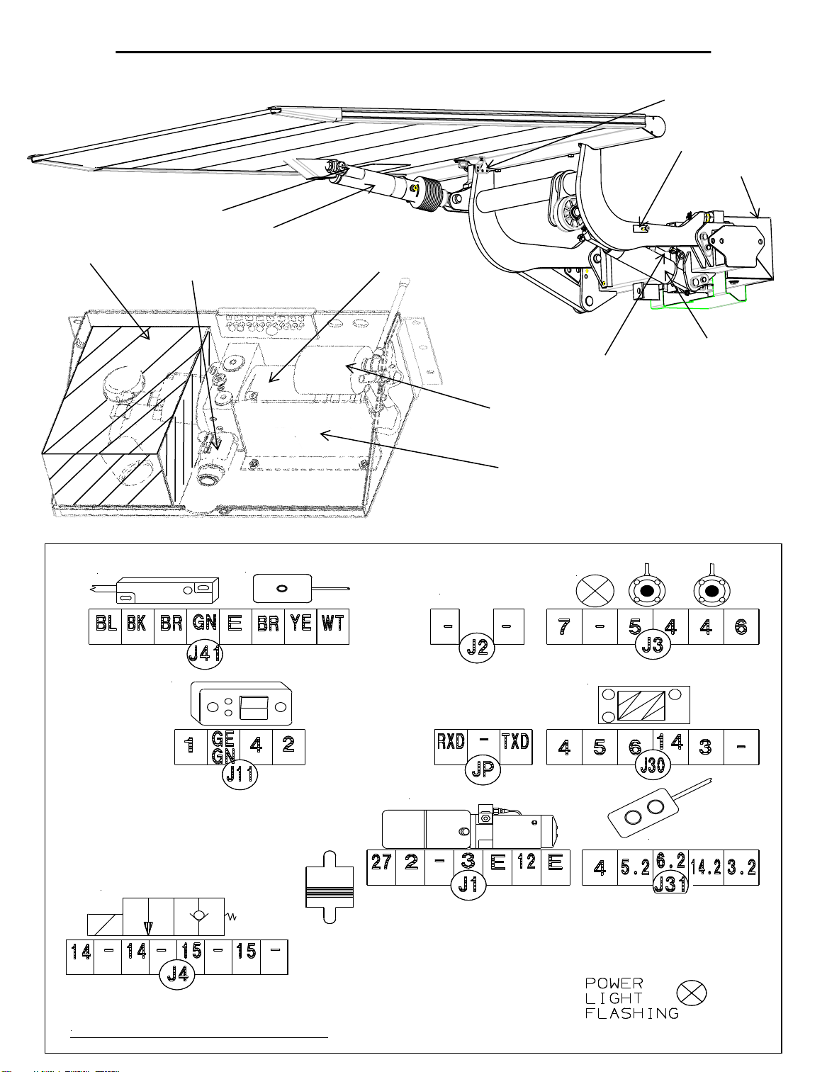
d) Check power on board between J-11 #4 and J-2 (-) with voltmeter by pushing the
up-function knob and hold for 10 sec with gate in stored position (DEADHEAD GATE)
(above 10 Volt is necessary for proper use of liftgate) less than 10 V; Jump #2 to #4
on J-11voltage jumps more than 1volt, call Palfinger for assistance
****DO NOT LEAVE JUMPER ON J-11 –GATE MUST BE SHUT OFF WHEN NOT IN USE****
1.1) Check Battery Power
a) Unplug J-3(foot control), J-41(B-13, B16, jump J-11 #4 to J-41 #GN) and J-31(Hand control)
Keep the 3 connectors unplugged (gate will operate without plugs connected, loose auto tilt)
b) Unplug J-1 (Main power), wait 10 seconds and plug J-1 back to the board (Reset the board)
c) Plug each connector back, one at a time and check functions of gate after plugging in each
1.2) Check for short in optional equipment
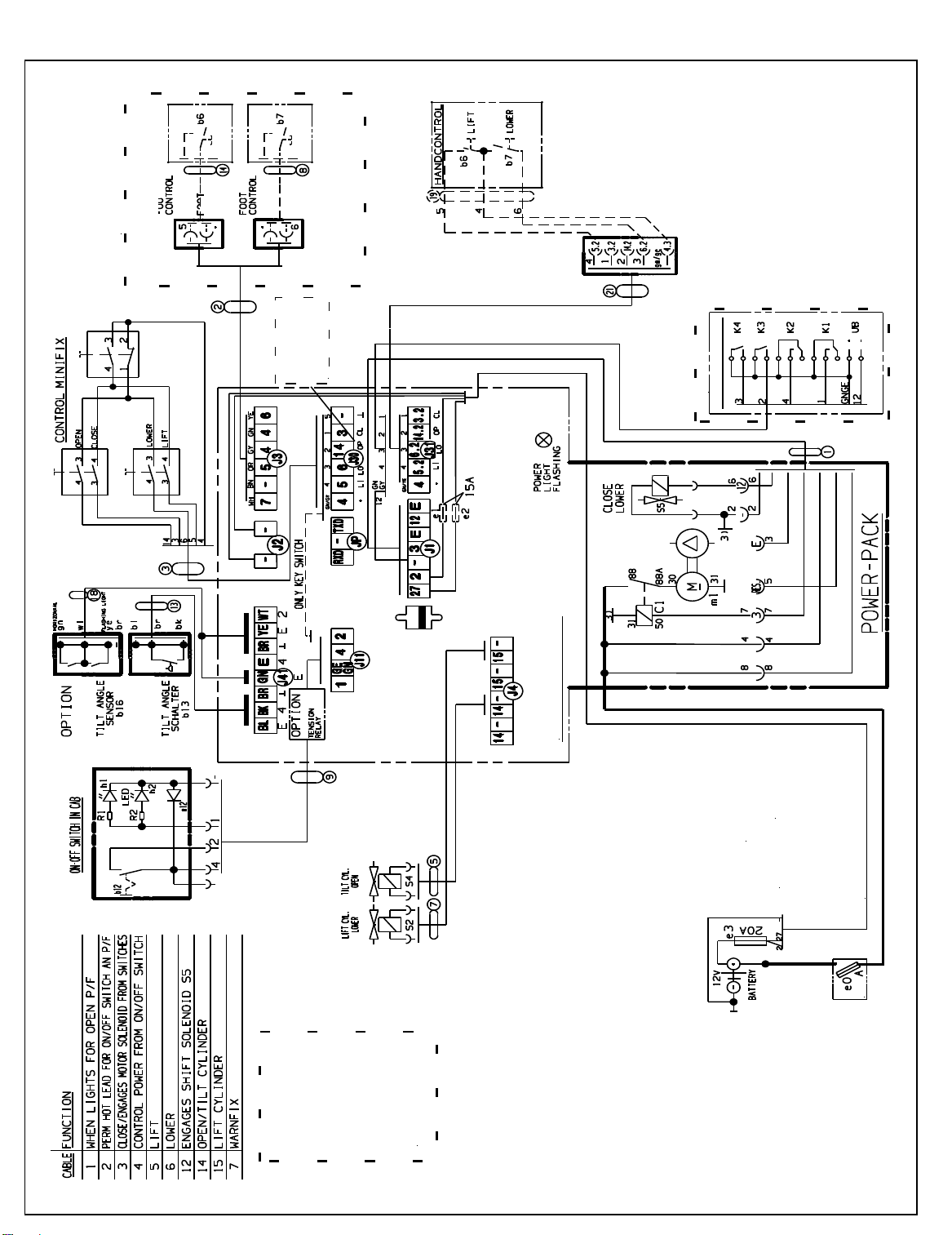
a) Check voltage at J4 #14 and Ground J-2 #(-) while pushing the open knob for opening up the release
valve S2 at the tilt cylinder. No Voltage check for bad knob or loose wire to control panel.
b) Listen for clicking of the release valve at the tilt cylinder (connected to platform)
- If valve is not clicking check wire for damaged spots, loose connections or a bad valve
1.3) Check voltage supply to release valve on tilt cylinder
a) Check voltage at J-1 #3 and Ground J-2 #(-) while pushing knob to engage motor solenoid
No voltage board might be damaged
b) Check voltage at small motor solenoid terminals and Ground J-2 #(-) while pushing knob and
listen for clicking of the motor solenoid –no voltage or clicking check wire to motor solenoid
c) Check for voltage across the small motor solenoid terminals with test light while pushing knob
See a light power is reaching solenoid.
d) Check for main power at the big solenoid studs, one has voltage; if not check connections to battery
e) Check both big solenoid studs for voltage while pushing the opening knob if not solenoid is bad
f) Jump large terminals at motor solenoid
- If motor runs motor solenoid is bad
- If motor does not run Bad motor or bad ground
- Tap on motor motor starts running –bad brushes
1.4) Check motor solenoid power
Minifix +
series