Palstar Commander VHF-1200 User manual

VHF-1200 / VHF-2000
6 M LINEAR AMPLIFIER
Owner’s Manual
PALSTAR, INC.
Command Technologies Division
9676 N. Looney Road
Piqua, Ohio 45356
U.S.A.
Customer Service and Sales Telephone: 00-773-7931
International: 937-773-6255
Fax: 937-773- 003
E-mail: [email protected]

2
Table of Contents
Introduction 3
S ecifications 4
Un acking Instructions 6
Installation Pre aration 6
HV Transformer Installation 7
Safety Warnings and Precautions 8
Connections 9
O erating Procedure 9
Ty ical O erating Conditions 11
Circuit Descri tion and Adjustments 12
Tuned In ut & T/R Relay Schematic 14
Control and Bias Board Schematic 15
Meter Board Schematic 16
High Voltage Power Su ly Schematic 17
VHF-1200 RF Deck Schematic 18
VHF-2000 RF Deck Schematic 19
Warranty, Service, and Returns 20

3
INTRODUCTION
The Commander VHF-1200 and VHF-2000 are Grounded Grid class AB2 linear ower
am lifiers that o erate on the Amateur 6 Meter band.
Over-drive and over-grid current rotection is rovided by an auto-reset circuit that laces
the am lifier in standby if a reset grid current limit is exceeded.
Genuine CPI/Eimac 3CPX800A7 external anode triodes, with forced air cooling and
modern circuitry, insure efficient and conservative o eration. The VHF-1200 uses one
tube, the VHF-2000 uses two.
6:1 Vernier reduction drives on all tuning controls allow smooth and easy tune-u .
A rear anel in ut tuning control allows a higher in ut circuit Q for excellent linearity
and a low in ut VSWR across the 6 Meter band.
An automatic delay circuit, for ro er cathode conditioning before RF drive can be a -
lied, extends tube life. A 50 ohm resistor in the late su ly ositive lead and a 200 ohm
resistor in the negative lead rotect the tube in the event of an arc.
The Commander VHF-1200 and VHF-2000 feature a full com liment of control and me-
tering functions for easy on-the-air o eration.
A dual rimary ower transformer allows 200/234 VAC o eration.

4
Specifications
Commander VHF-1200
6 M Linear Power Amplifier
• Modes: USB, LSB, RTTY, FM, & CW
• Power Requirements: 200/234VAC 50/60 Hz.
• RF Drive Power: 15-25 W Nominal; 35-40 Watts Max. For Full Out ut (1.2 kW PEP on
SSB)
• RF Output: 750 W maximum, FM or RTTY
• Input Impedance: 50 Ohm unbalanced; rear anel adjustable
• Output Impedance: 50 Ohm nominal
• Antenna Load: 2:1 VSWR maximum
• Harmonic Suppression: Better than -60 db down @ rated out ut
• Intermodulation Distortion: Better than -35 db down @ rated out ut
• Weight: 75 lbs (34 kg)
• Cabinet Size: 18” x 16” x 7.75” (45.7 cm x 40.6 cm x 19.7 cm)
• Tube Compliment: One 3CPX800A7 Ceramic Metal Triode
• Cooling: Forced air, ressurized chassis

5
Specifications
Commander VHF-2000
6 M Linear Power Amplifier
• Frequency Range: 50 to 54 MHz
• Modes: USB, LSB, RTTY, FM, & CW
• Power Requirements: 200/234VAC 50/60 Hz.
• RF Drive Power: 15-25 W nominal - 35-50 W Max. for full out ut (1.5 kW PEP on SSB )
• RF Output: 1500 W maximum, FM or RTTY
• Input Impedance: 50 Ohm unbalanced; rear anel adjustable
• Output Impedance: 50 Ohm nominal
• Antenna Load: 2:1 VSWR maximum
• Harmonic Suppression: Better than -60 db down @ rated out ut
• Intermodulation Distortion: Better than -35 db down @ rated out ut
• Weight: 75 lbs (34 kg)
• Cabinet Size: 18” x 16” x 7.75” (45.7 cm x 40.6 cm x 19.7 cm)
• Tube Compliment: Two 3CPX800A7 Ceramic Metal Triodes
• Cooling: Forced air, ressurized chassis

6
UNPACKING
Carefully remove your VHF-1200/VHF-2000 Am lifier from its shi ing carton making
sure there is no damage evident from shi ing. If there is any damage, notify the delivering
shi er immediately, fully describing the damage.
The HV ower transformer was shi ed se arately, as its weight would damage the cabinet
in transit.
The 3CPX800A7 tube(s) are acked inside the cabinet in the area where the transformer
will be installed.
Do not destroy the acking material since it may be reusable later, should you require fac-
tory service or need to trans ort the Am lifier for any other reason.
TRANSFORMER INSTALLATION
See the illustrated rocedure on age 7 to com lete installation.
TUBE INSTALLATION
Carefully remove the 3CPX800A7 tube(s) from the shi ing carton. This carton was located
in the area where the transformer was installed. Place the tubes in the tube socket with the
ro er in alignment. If you have maintained the ro er in alignment, the tubes should go into
their sockets easily. If you have to use undue force to insert the tubes, you may have the wrong
in alignment or one or more of the ins may be bent. If necessary, carefully straighten ins
with needle nose liers and reinstall. Install the anode stra s on the tube ca s as shown and re-
lace the to and bottom covers. The unit is now ready for o eration.
200/234 VAC Operation
The Commander VHF-1200 and VHF 2000 come factory wired for 234 VAC o eration. For
best o eration, you should use a dedicated 234 VAC main ca able of su lying 20 Am s of
eak AC current.
Commander Am lifiers manufactured for ex ort are wired for 234 VAC or 200 VAC de-
ending on the final destination.

7
Gri the transformer by the windings, as shown.
There is not enough room for your hands inside the
cabinet if you hold it by the base.
Carefully lower the transformer into the am lifier. Be
careful not to bum the backs of the meters and be
sure the connector lug is out of the way and will not
be tra ed under the transformer.
Position the transformer over the mounting holes in
the cabinet and insert the rovided carriage bolts in
from the to , through the transformer mounting tabs
and chassis slots. Next, slightly lift the chassis and
lace a flat washer and KEPS nut on the bottom side
of each bolt and tighten.
Plug the connector on the transformer into the one on
the wiring harness. It is keyed so that it cannot be
lugged in backwards. Make sure that the connector
halves are ressed together until the lock tabs sna in
lace.
This is the final osition of the transformer and the
connector lug.

CAUTION:
• DO NOT attem t any ty e of service or re air on this am lifier without first removing the
AC ower and allowing AT LEAST 60 MINUTES FOR THE HIGH VOLTAGE CAPACI-
TORS TO BLEED OFF !
• DO NOT o erate this am lifier with the to or bottom covers removed. DO NOT o erate
this am lifier with the internal RF tube com artment covers removed. Never lace any ob-
jects into the to ventilation holes. CONTACT WITH VOLTAGES IN THE CABINET
CAN BE FATAL ! EXPOSURE TO UNSHIELDED RF AT THESE POWER LEVELS
IS HAZARDOUS TO YOUR HEALTH !
• Never attem t o eration without first connecting an a ro riate antenna (2:1 VSWR Max)
or a 50 ohm dummy load with sufficient rating or SERIOUS DAMAGE TO THE AMPLI-
FIER MAY RESULT.
• Never o erate the am lifier with more drive than required to roduce the rated out ut for
the o erating mode used.
• Do not lace the VHF-1200 OR VHF-2000 in re eater o eration. These am lifiers are not
designed for unattended service.Never o erate any am lifier using an extension cord.
• Never cover the to of the am lifier cabinet with books, a ers or other equi ment as
OVERHEATING MAY RESULT.
FOR ASSISTANCE CONTACT THE MANUFACURER:
Tele hone: 800-773-7931
International: 937-773-6255
E-mail: info@ alstar.com
!! WARNING !!
CONTACT WITH VOLTAGES IN THIS AMPLIFIER CAN BE
!!! FATAL!!!

9
CONNECTING YOUR AMPLIFIER
Locate your Commander VHF-1200/2000 so that no equi ment is directly above it, as air
ex elled from the tube exhaust on to can become quite hot. Allow at least 3 inches clearance
on either side between the unit and other objects or equi ment.
Connect the RF OUTPUT of your transceiver to the RF IN connector on the rear of the
VHF-1200/2000 with 50 ohm coax.
Using RG8 or better coax, connect the RF OUT connector on the VHF-1200/2000 to a good
quality thruline Wattmeter, and connect the Wattmeter Out ut to the antenna, antenna tuner or
dummy load.
Connect the RELAY hono jack on the rear of the VHF-1200/2000 to the Normally O en
(NO) terminal of the RELAY jack on your transceiver. Read the manual that came with your
transceiver to find the ro er external connections. On some transceivers, this is not rovided,
and an alternate circuit will be required. Always use shielded cable for these connections. The
RELAY jack on the VHF-1200/2000 has ositive 12 VDC o en circuit on the center in and
requires the sinking of 55 mA of current when ulled to ground.
Connect the ALC hono jack to the ALC connection on your transceiver using a shielded
cable. Consult your transceiver manual for ro er ALC connection details.
Connect a ground lead (as short as ossible) from a good earth ground to the GROUND
ost on the rear anel.
The 12 VDC jack on the rear anel is an accessory for owering low current 12 VDC de-
vices (less than 100 mA.). Do not connect an external voltage source to the jack.
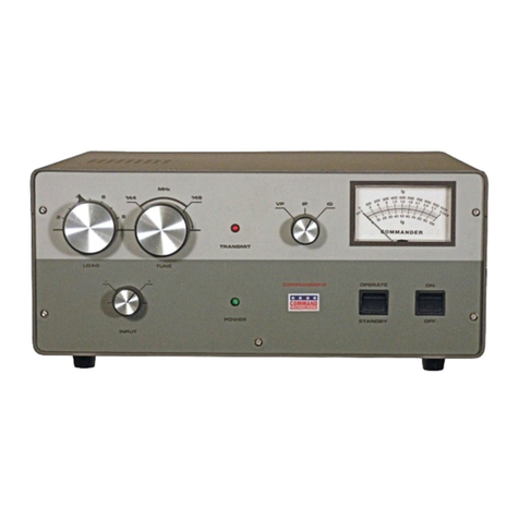
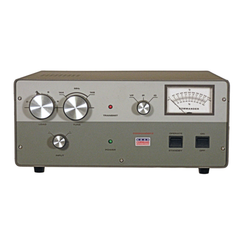
OPERATING PROCEDURE
After reading this manual and com leting the Installation / Pre aration Instructions, osition
the Commander VHF-1200/2000 front controls as follows:
ON / OFF OFF
OPERATE / STANDBY STANDBY
METER SWITCH V (PLATE VOLTAGE)
LOAD 50 - MIDDLE OF RANGE
TUNE MINIMUM CAPACITANCE (POINTER TO LEFT)
After resetting these controls, switch the ON/OFF switch to the ON osition. At this time
you will hear the blower running and see an indication of Plate Voltage on the meter, (a rox-
imately 2650 VDC)
The 3CPX800A7 used in this am lifier require a warm-u eriod before RF drive may be
a lied, to revent damage to the tube. A 2 minute warm-u is rovided by a solid state timer
circuit. At the end of the warm-u eriod, the green POWER LED on the front anel illumi-
nates and the unit is ready for o eration. Switch the meter switch to the I ( late current) osi-
tion.

10
Switch the OPERATE / STANDBY switch to OPERATE and key the exciter with ZERO
RF drive a lied. The red transmit light should come on, along with an indication of late
idling current on the meter (a rox. 100-160 mA VHF-2000; 80-100 mA VHF-1200). A ly a
low level of RF drive (5 W or less) and adjust the LOAD and then the TUNE control for maxi-
mum out ut as indicated on an external Wattmeter. COMPLETE THESE ADJUSTMENTS AS
QUICKLY AS POSSIBLE TO AVOID STRESSING THE TUBE(S).
Again key the exciter and while increasing the RF drive, adjust the LOAD control counter-
clockwise to obtain a eak in out ut ower while kee ing the grid current below 60mA. Read-
just the TUNE control clockwise for maximum out ut. Re eat this rocedure until the desired
out ut is obtained. When increasing ower out ut, the TUNE ca acitance will increase (clock-
wise on the dial) and the LOAD ca acitance will decrease (counterclockwise on the dial) When
ro erly tuned, the grid current will be eaked at the TUNE setting and turning the LOAD
counter-clockwise will decrease grid current and ower out ut. If the grid current rises, kee
turning LOAD counter-clockwise until it decreases. Do not exceed 600 mA (VHF-1200) or
1000 mA (VHF-2000) of late current on key down (see ty ical o erating conditions chart on
next age). If you exceed 70 mA (VHF-1200) or 100 mA (VHF-2000) of grid current the am-
lifier will dro out to Standby. To reset it, you will have to un-key the transmitter and reduce
RF drive.
With the meter switch in the I osition and while monitoring grid current, the Commander
VHF-1200/2000 is ready for on the air o eration. Normal SSB o eration is indicated by late
and grid current meter readings on voice eaks of a roximately 1/3 to 1/2 of the CW key down
value. For FM or other high duty cycle modes, limit out ut to 600 watts (VHF-1200) or 1000
watts (VHF-2000) maximum.
If your lanned o eration is on SSB, you should adjust the load control slightly counter-
clockwise, reducing the out ut slightly by about 30 to 50 watts. This adjustment is necessary to
insure that the am lifier has sufficient headroom to handle the late current eaks caused by the
com lex voice atterns during SSB o eration. Nominal and grid current readings during SSB
o eration will be about 30 to 40% of the key down CW readings.
CAUTION: THE TUNE AND LOAD AIR VARIABLE CAPACITORS
MAY ARC IF MAXIMUM DRIVE IS APPLIED BEFORE THE AMPLIFIER
IS PROPERLY TUNED. ALWAYS FOLLOW THE DESCRIBED TUNE UP
PROCEDURE TO AVOID CAPACITOR ARCING. ARCING MAY ALSO
OCCUR IF YOU ATTEMPT TO TUNE INTO AN ANTENNA WITH A
VSWR GREATER THAN 2:1.
If you should need any further assistance tuning this am lifier, feel free to call us at 1-800-
773-7931 and our staff will be ha y to hel you. If you are outside the United States we are
available at 937-773-6255
11
DRIVE GRID CURRENT PLATE CURRENT POWER OUTPUT
12.5 Watts 20mA 400mA 450 Watts
18.5 Watts 30mA 500mA 650Watts
30 Watts 50mA 600mA 1000Watts
DRIVE GRID CURRENT PLATE CURRENT POWER OUTPUT
25 Watts 30mA 700mA 1000 Watts
40 Watts 45mA 1000mA 1500 Watts
Typical Operating Conditions
VHF-1200
Typical Operating Conditions
VHF-2000

12
Circuit Description and Adjustments
The Commander VHF-1200/2000 uses Genuine Eimac 3CPX800A7 ceramic/metal triodes)
in a class AB2 grounded grid configuration. Nominal drive ower of 35 to 50 Watts will deliver
full rating of clean RF out ut ower.
Metering Functions
The Commander VHF-1200 and VHF-2000 have two illuminated anel meters. The Grid
Current meter rovides a continuous reading of the 3CX8QQ-A7s grid current. The meter scale
is 2 mA er division and the range is 0 to 100 mA. DO NOT EXCEED 60 mA OF GRID CUR-
RENT PER TUBE (60 mA on the VHF-1200; 120 mA on the VHF-2000). OTHERWISE,
DAMAGE TO YOUR TUBES COULD RESULT. Under ty ical o erating conditions the grid
current will be 20-45 mA on the VHF-1200; 40-90 mA on the VHF-2000.
Plate voltage and Plate current are shown on the second meter. A function switch on the
front anel switches the meter from late voltage (V ) to late current (I ). Plate current is
shown on the to scale. Each division is 20 mA, and full scale is 1500 mA. (1000 mA VHF-
1200)
The ty ical late current under nominal rated out ut should range from 900 to 1100 mA.
(500 to 600 mA on VHF-1200) with an absolute maximum of 1200 mA. for SSB. (600 mA
VHF-1200) Plate voltage is indicated on the bottom scale with each division reflecting .06 kV.
The scale has a range from 0-3.0 kV. The nominal no-load late voltage should read a roxi-
mately 2,600 V. Plate voltage under nominal full load should read a roximately 2,300 V.
Control
An adjustable automatic level control (ALC) circuit limits the eak out ut ower. When
ro erly set, this circuit insures that the am lifier can not be over driven. Rear anel access al-
lows for easy manual adjustment . A sam le of the RF in ut derives the ALC voltage. Addition-
ally this am lifier has an RF negative feedback resistance in the cathode circuit to hel cancel
excessive RF drive without reducing the am lifier's gain.
A.L.C. Adjustments
Your transceiver's internal ALC will maintain linearity. The am lifier's ALC will revent
over driving the am lifier. The VHF-1200/2000 ALC circuit was designed for negative going
ALC voltage. Pro er adjustment is as follows:
1. Use an insulated tool when making these adjustments.
2. Tune the am lifier for o eration on the desired frequency for full 1500 W out ut.
(1200 W on the VHF-1200)
3. With your transceiver set for SSB o eration, set the transceiver's micro hone gain
for normal o eration as s ecified in its owners manual.
4. While s eaking louder than normal into the micro hone, adjust the ALC control on
the rear anel through the access hole. Adjust for 1500 W (1200 W on VHF-1200)
maximum out ut as indicated on an external eak reading wattmeter. If an average
reading wattmeter is used, adjust for a roximately 600 W out ut on voice eaks.
(400 W on VHF-1200)

13
Tuned Input Circuits
The tuned in ut circuits utilize an L-C-L or "T" im edance matching circuit with a high Q
design. These circuits em loy RF hase com ensating inductors to reduce intermodulation
roducts. The use of mica trimmer ty e ca acitors allows adjustments to recisely match the
transceiver to the am lifier. The rear anel rovides easy access to these trimmer ca acitors.
Tuned Input Adjustments
Your Commander am lifier has a mica trimmer ca acitor which is easily accessed through
the rear anel. The tuned in ut circuits are factory tuned and should not require any readjust-
ment. You can easily make adjustments for any change in your reference for o erating fre-
quency range. Also, slight adjustments may be necessary because of slight variances in im ed-
ance between your transceiver and the tuned in ut circuitry of the am lifier.
1. Install a SWR meter between the transceiver and the am lifier.
2. Make sure the O erate/Standby switch is in the o erate osition and Your am lifier
should also be ro erly tuned and loaded.
3. A ly drive and observe the SWR, and adjust the trimmer ca acitor for minimum SWR.
Be careful not to overdrive the am lifier.
Output Filter Circuit
The π variable network filter transforms the late load im edance from a roximately 1600
ohms down to 200 ohms, Two air variable ca acitors and an associated inductor accom lish
this transformation. A design Q of 14 allows for good harmonic attenuation all across the band.
The utilization of a s ecial reactance tuned owdered iron core 4 to 1 transmission line trans-
former ste s the nominal 50 ohm antenna im edance u to the 200 ohm out ut of the π circuit.
This also achieves further harmonic attenuation of the out ut in the same manor as an "L" coil
in a π - L network. Additional harmonic attenuation is accom lished with a band ass filter on
the out ut.
High Voltage Supply
The high voltage su ly o erates from a 200/234 VAC 20 am ere line. The rimary of the
high voltage transformer is switched on/off with solid state relays that during ower u only
conduct when the hase angle of the AC ower line is at the 0 to +30 degree crossover oint.
This minimizes line surge and inrush current while the high voltage filter ca acitors charge. The
front anel on/off switch activates the solid state relays with 2 mA AC to turn the unit on. A -
roximately 900 VAC is fed to a full wave voltage doubler rectifier circuit. This su lies
a rox. 2600 VDC to the 3CPX800A7's anodes. Metering of the tubes anode and grid current is
accom lished by shunt resistors located in the negative return of the 3CPX800A7's cathodes.
Plate voltage metering is accom lished by a resistor multi lier network in the B+ line of the
high voltage circuit.

14
Tuned 6 M Input
T/R Relay

15
Control Board

16

17
HV Power Supply

1
RF Deck

19
RF Deck

20
Limited Warranty
Palstar Inc. warrants the VHF-1200 and VHF-2000 to be free from defects in material and
workmanshi under normal use and service to the original buyer for a period of one (1) year
from the date of delivery to that buyer (the “Warranty Period”). Palstar Inc.’s obligation un-
der this warranty is limited to re air or re lacement of the roduct at it’s o tion at the Palstar
factory in Piqua, OH.
This warranty is effective only when the roduct is returned to the factory with all trans or-
tation charges re aid and examination of the roduct discloses the roduct, in Palstar’s judg-
ment, to have been defective during the Warranty Period.
The Warranty Period shall not extend beyond its original term with res ect to interim in-
warranty re airs by Palstar. This Warranty Period shall not a ly to any roduct which has been
re aired or altered by anyone other than Palstar without rior written authorization. Warranty
does not extend to any roducts which have been subject to damage from im ro er installation,
a lication or maintenance in accordance with the o erating s ecifications. Palstar neither as-
sumes nor authorizes any erson to assume for it any obligation or liability other than herein
stated.
Shipping Your Amplifier Back to the Factory
Due to the necessity of shi ing the am lifier with the HV transformer removed, lease
contact the factory for instructions before sending an am lifier back to us. There are circum-
stances in which it may not be necessary to return the HV transformer, thereby saving you shi -
ing charges. When you call, Palstar will inform you if transformer return is necessary. If
transformer return is necessary, remove it from the am lifier cabinet and shi it se arately,
referably in its original acking.
Repair Policy
When sending in a roduct for service, see the section above. If not using the original ack-
ing materials, lease “double” box it carefully with suitable adding and shi it insured for your
rotection. Please include a note clearly describing the roblem, how you wish the item re-
turned and how you wish to ay for the service. Package your unit ro erly. Palstar, Inc. is not
res onsible for merchandise damaged in shi ment. Our service rate is $30 er hour (1/2 hr.
minimum).
Return Policy
All returns must receive rior authorization from Palstar. Returned items must be received in
original—AS SHIPPED—condition including the original box, manuals, accessories, and co y
of sales recei t. Returns must be within 14 days of urchase. Returned items are subject to a
25% restocking fee. Shi ing is not refundable.
This manual suits for next models
3
Other Palstar Amplifier manuals

Palstar
Palstar COMMANDER HF-2500 EXPORT User manual

Palstar
Palstar COMMANDER II 2 METER VHF User manual

Palstar
Palstar COMMANDER II User manual

Palstar
Palstar LA-1K User manual

Palstar
Palstar COMMANDER VHF-144 User manual

Palstar
Palstar COMMANDER HF-2500 EXPORT User manual

Palstar
Palstar LA-1K User manual