Palstar LA-1K User manual

Palstar products are designed by
Hams for Hams carrying on the
Palstar tradition for high-quality
products designed and
manufactured in Ohio, USA.
LA-1K RF SENSING 1000W
DUAL HF LDMOS AMPLIFIER
1000 watts PEP CW ICAS (160 m to 6m)
RF Sensing Auto Band Switching
Color TFT touch screen
Variable speed fans
12.75” x 6.25” x 16.5”
9676 N. Looney Rd,
Piqua, OH 45356 USA
(937) 773-6255
(800) 773-7931
(937) 773-8003 (Fax)
www.palstar.com
LA-1K RF SENSING 1000W
DUAL HF LDMOS AMPLIFIER
Technical Manual
Designed and Manufactured in the USA
Copyright 2017 Palstar, Inc.
PALSTAR
PALSTAR

SSB POWER: 1000 Watts PEP CW ICAS
CW MODE: Power levels up to 850W
FM/RTTY: 500 watts
AM: 275 watts
FREQUENCY RANGE: 1.8 TO 54 MHz
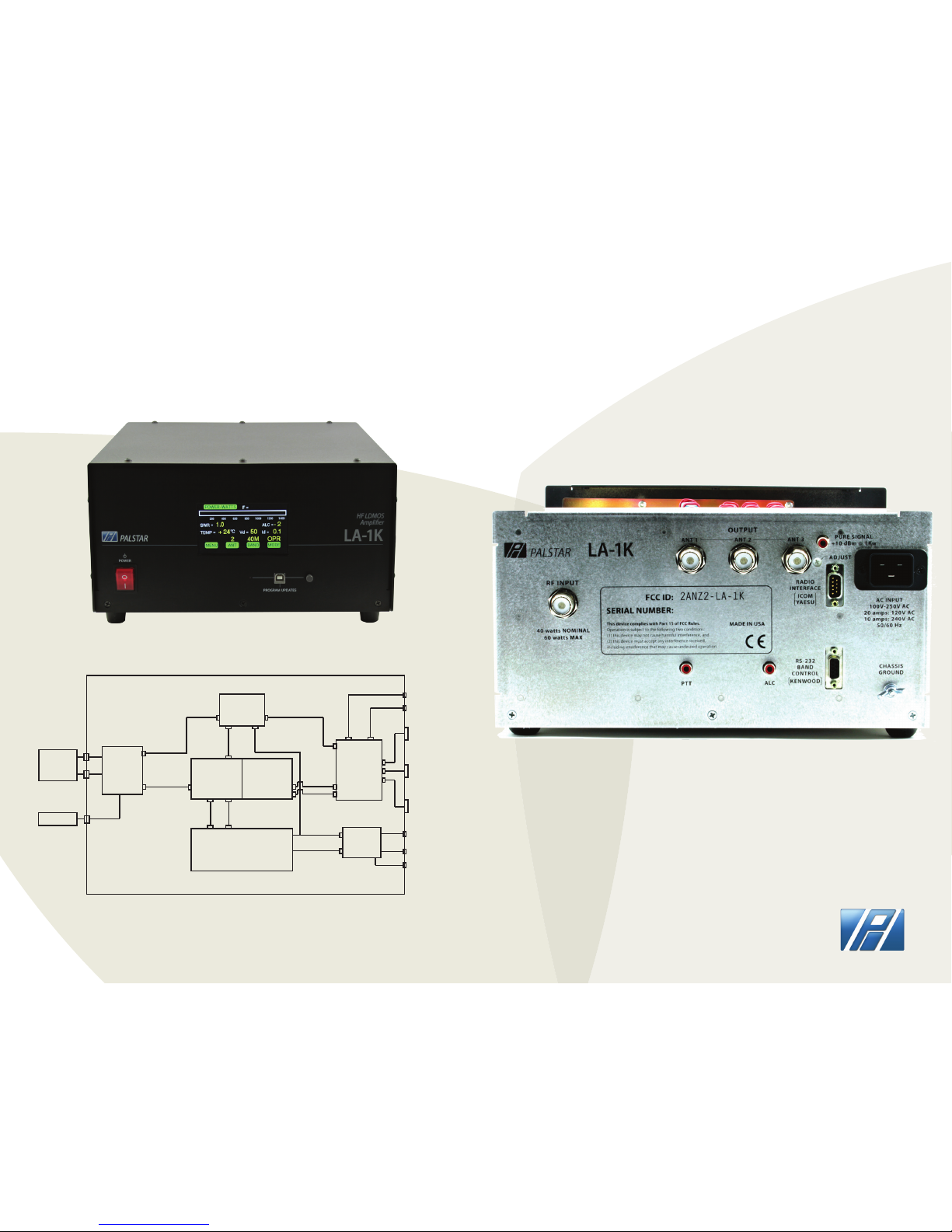
DISPLAY: Color TFT touch screen
INPUT DRIVE LEVEL: 45W - 65W (ALL BANDS)
OUTPUT: 3 x RF SO-239 or Type N
ALC: Exciter power control
DRIVE REQUIRED: 40-55W (All Bands)
GAIN: 13+/-1dB (Nominal)
RF SENSING: Auto band switching
RF OUTPUT: Vacuum RELAY T/R Switching
POWER SUPPLY: Internal Medical grade
DC SUPPLY: 100VAC - 250VAC/50V@42A
POWER DEVICES: 2 x 5600H 600W (LDMOS)
AUTO-PROTECT: SWR/Short Circuit
INTERMOD: Low IMD Distortion >-35dB
PURE SIGNAL: Sample@+10dBm (Rear Panel@1kW ouput)
COOLING: Variable Speed Fans (3 speed)
CHASSIS: .090 ga. aluminium
TOP COVER: .090 ga. aluminium, powder coated
DIMENSIONS: 12.75” W x 6.25“ H x 16.5” D
WEIGHT: 27 LBS, 12.25 Kg
DESIGN CONCEPT: Full compatibility with Palstar
HF-AUTO autotuner
WARRANTY: Two year
LA-1K SPECIFICATIONS
Page 1 PALSTAR
The LA-1K RF Sensing Dual HF LDMOS amplier is a complete
stand-alone amateur RF LINEAR amplier.
It is completely independent of data from an external source to
determine frequency for tracking from Band to Band. As a result of this
feature, the LA-1K will function with any transmitting device without
interconnecting data cable attachments.
The power output of the LA-1K is 1000Watts PEP CW ICAS (Intermittent
Commercial and Amateur Service). Under the ICAS classication, the
use of the LA-1K is designed for transmissions that are of an
intermittent nature.
Intermittent operation of the LA-1K implies that no operating or
“ON” period of 1000W of Continuous Carrier Power will exceed
approximately 1(ONE) minute. On Single Side Band (SSB) voice
duty there is no limit on transmit time at full power of 1000W PEP.
Every “on” period must be followed by an “o” or standby period of at
least the same or longer duration. The LA-1K provides a +10dBm@1kW
RF tap feed at the rear panel to provide provisions for “PURE SIGNAL”
operation provided by compatible transceivers. The level adjustment
is calibrated at the factory. The LA-1K was designed to be fully
compatible with the Palstar HF-AUTO automatic antenna tuner.
Included with the LA-1K:
• Two (2) line cords for 110VAC and 220VAC
• User Manual
• Amplier unit
• Shipping box (please keep box for warranty repair, etc.)
As per FCC 15.21 changes or modications not expressly approved
by Palstar could void the user's authority to operate the
equipment. No tune up procedure exists.
THEORY OF OPERATION

PALSTAR
ON INITIAL POWER-UP
Display will indicate STBY mode (stand-by). To switch
mode press the “MODE” button on the tourchscreen
display to switch into “OPR” mode (operational).
SCREEN DISPLAY ON POWER-UP
Page 2
STAND-BY MODE
OPERATIONAL MODE TRANSMITTING
NOTE: Wattmeter only shows RED power bar graphical
indicator when the LA-1K is transmitting.
OPERATIONAL MODE
OPERATIONAL MODE
OPERATIONAL MODE
To switch into Operational mode “OPR” press the “MODE”
button on the touchscreen display. The touchscreen
menu will display “OPR” mode (operational). The red
power bar graphical indicator will only be visible when
transmitting.
Automatic band selection when user transmits
Automatic antenna selection of last used antenna output when
bands selected
Over temperature protection by fan speed control, and bypass
mode if temperature exceeds 100° C (fault temperature shows on
display)
Unit is locked in Bypass until temperature drops below 70°C
Frequency operation lock-out from 25.99MHz - 28.00MHz
ADDITIONAL FEATURES

PALSTAR
Page 3
OPERATIONAL MODE
BAND SELECT
To switch bands, 160M-80M-40-30M-20-15M-12-10M-6M,
press the “BAND” button on the touchscreen display,
then select desired band. The LA-1K selects the proper
band automatically when transmit is activated.
ANTENNA SELECT
To switch antennas between ANT 1(Coax 1), ANT 2 (Coax
2), and ANT 3 (Coax 3), press the “ANT” button on the
touchscreen display, then select desired antenna ouput.
This setting will automatically select when changing
bands to the last one used on any particular band. The
default value is ANT 1.
OTHER MENU OPTIONS
SELECT BACKLIGHT
To adjust the backlight on the touchscreen display press
MENU.
Press and hold the < or > arrows to adjust BACKLIGHT
LOW (screen intensity when no buttons are pressed) and
select NEXT and then < or > arrows to adjust BACKLIGHT
HIGH (screen intensity when buttons are being pressed).
SELECT BACKLIGHT LOW/HIGH

PALSTAR
LA-1K Front & Rear Panel
Page 4
RF DECK
BIAS
POWER SUPPLY
+12 -12
REAR
PANEL
AC
FILTER
50v@42A POWER SUPPLY
FRONT
PANEL
DISPLAY
PROGRAM
ANT 1
ANT 2
ANT 3
AC (100v-240)
LA-1K BLOCK DIAGRAM
DATA
INPUT
LPF/DF

PALSTAR
USING PTT
Rear Panel RF Deck Front Panel
AC input lter +/-12V (BIAS)
+50V@42A
Power Supply
Dual output
lters
The phono input PTT can be activated by any transceiver.
When PTT is grounded in the LA-1K it is ready to
transmit.
Page 5
OTHER MENU OPTIONS
SELECT ALC BASE VALUE
To adjust ALC base value select menu on the touchscreen
display.
Press and hold the < or > arrows to increase or decrease
ALC BASE VALUE. If using ALC this should be adjusted
carefully to match your transceiver’s requirements
(usually -1.5V approximately).
ALC BASE VALUE

PALSTAR
Page 6
LA-1K FIRMWARE SUMMARY HOW-TO UPDATE FIRMWARE
DOWNLOADING LA-1K FIRMWARE
CREATE a folder on your computer’s hard drive
NAME the folder LA_1KFIRMWARE
DOWNLOAD the Firmware le (Zip format) from the Palstar website,
http://www.palstar.com/en/la-1k/. The download link is near the bottom of
the page. The link to the le is named“LA-1K Firmware x.x”
SAVE the le to the folder you created in Step 1
OPEN the folder by right-clicking on the Zip le and select “Extract All” -
follow the steps in the Extraction wizard
CONNECT one end of the USB cable to a USB port on your computer.
DOUBLE-CLICK “LOAD_LA-1K” within your LA_1KFIRMWARE folder that you
created in Step 2.
Follow the instructions on the opened computer window and use the
"Browse" button to select the rmware version to be loaded.
Depress and hold down the GREY button to the right of the USB port
labeled “PROGRAM UPDATES” during the next two steps.
CONNECT the other end of the USB cable to a USB cable to the LA-1K front
panel.
TURN-ON the LA-1K. A "Found 1 device" message will appear on the right
side of the opened computer window.
Release the GREY button on the LA-1K front panel.
Click on the "Update Firmware" button that is on the opened computer
window. Wait until the green bar in the middle of the computer window
shows that the programming completes by lling from left to right. The
rmware version number on the LA-1K is on the bottom line of the start up
screen.
SEE WEBSITE FOR FIRMWARE SUMMARY:
http://www.palstar.com/en/la1k/
POWER SUPPLY PERFORMANCE
If the LA-1K is used on 120VAC the max current rating is
between 33A to 34A. The power output in some of the
bands may be lower than 1000 watts if a steady RF carrier
is used in CW, for example.
If the current exceeds 34 Amps, the power supply will
shut down and the Vd reading on the TFT display will
read ZERO (operation@120 VAC).
The power supply will immediately come back on in 1 to
2 seconds and the display will read 50V again. Reducing
drive from 5 to 10 watts will prevent this from occuring.
The medical grade power supply will not be damaged as
this feature has been designed into the power unit of
the LA-1K.
For 230-250 VAC operation at full power of 1000W PEP is
available on all bands. It is recommended that 240VAC
be used for all modes.

PALSTAR
EXTERNAL DATA CONNECTORS
Page 7
The LA-1K automatically selects bands and it is normally not necessary
to connect band data cables between your transceiver and the LA-1K
amplier.
RADIO INTERFACE CONNECTOR:
This connector is designed to be
pin for pin compatible with other
ampliers. The required cables are
widely available. They can be used
to connect to ICOM and YAESU
transceivers.
XCVR Interface
[Radio Interface Pin Out]
Pin Function
1 BCD B IN
2 BCD A IN
3 Kenwood RX (data in) [custom cable required]
4 Kenwood TX (data out) [custom cable required]
5 Icom Band Data
6 GND
7 Amp-Key IN
8 BCD D IN
9 BCD C IN
RS232 BAND CONTROL CONNECTOR:
This connector is designed to be used with Kenwood transceivers for
band selection using a null modem adapter. It is also designed to
control the amplier from a computer.
EXTERNAL DATA CONNECTORS
Table of YAESU/ELECRAFT
Band selections and
4 bit BCD codes
Band DCBA
60m 0000
160m 0001
80m 0010
30m 0011
20m 0101
17m 0110
15m 0111
12m 1000
10m 1001
6m 1010
NC 1111
0 = low voltage (0 volts)
1 = high voltage (5 volts)
Table of ICOM Band and
Voltage Level
Pin 5
NC 12 volts
160m 7.0-8.0 volts
80m 6.0-7.0 volts
40m 5.0-6.0 volts
30m 0.0-1.0 volts
20m 4.0-5.0 volts
17/15m 3.0-4.0 volts
12/10m 2.0-3.0 volts
6m 1.0-2.0 volts
Other manuals for LA-1K
1
Table of contents
Other Palstar Amplifier manuals

Palstar
Palstar COMMANDER HF-2500 EXPORT User manual

Palstar
Palstar COMMANDER HF-2500 EXPORT User manual

Palstar
Palstar Commander VHF-1200 User manual

Palstar
Palstar COMMANDER II User manual

Palstar
Palstar COMMANDER VHF-144 User manual

Palstar
Palstar COMMANDER II 2 METER VHF User manual

Palstar
Palstar LA-1K User manual