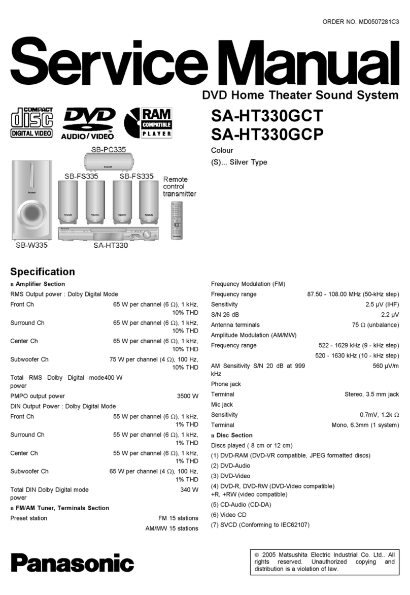
udio output (Disc)
Number of channels 5.1ch (FL, FR, C, SL, SR, SW)
nVideo Section
Video system
Signal system PAL625/50, PAL525/60, NTSC
Composite video output
Output level 1Vp-p(75Ω)
Terminal Pin jack (1 system)
Scart jack (1 system)
S-video output
Y output level 1Vp-p(75Ω)
C output level PAL; 0.3 Vp-p (75 Ω)
NTSC; 0.286 Vp-p (75 Ω)
Terminal S terminal (1 system)
Scart jack (1 system)
Component video output
[NTSC: 525 (480) p/525 (480) i, PAL: 625 (576) p/625 (576) i]
Y output level 1Vp-p(75Ω)
PB output level 0.7 Vp-p (75 Ω)
1 Safety Precautions 4
1.1. GENERAL GUIDELINES 4
2 Caution for AC Mains Lead 5
3 Before Repair and Adjustment 6
4 Protection Circuitry 6
5 Prevention of Electro Static Discharge (ESD) to
Electrostatically Sensitive (ES) Devices 7
6 Handling the Lead-free Solder 7
6.1. About lead free solder (PbF) 7
7 Precaution of Laser Diode 8
8 Handling Precautions for Optical Pickup Unit 9
8.1. Cautions to be taken in handling the Optical Pickup Unit
9
8.2. Cautions to be taken when replacing the Optical Pickup
Unit 9
8.3. Grounding for electrostatic breakdown prevention 9
9 Accessories 11
PR output level 0.7 Vp-p (75 Ω)
Terminal Pin jack (Y: green, PB: blue,
PR: red) (1 system)
RGB video output
R output level 0.7 Vp-p (75 Ω)
G output level 0.7 Vp-p (75 Ω)
B output level 0.7 Vp-p (75 Ω)
Terminal Scart jack (1 system)
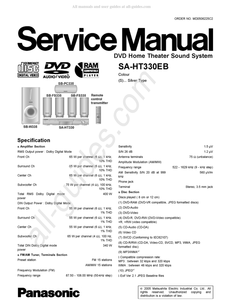
nGeneral
Power supply AC 230 - 240 V, 50 Hz
Power consumption Main unit 80 W
Dimensions (W x H x D) 430 mm x 60 mm x 337 mm
Mass Main unit 3.3 kg
Operating temperature range +5 °C to +35 °C
Operating humidity range 5%to90%RH(no
condensation)
Power consumption in standby
mode
approx 0.5 W
Notes :
1. Specifications are subject to change without notices.
Mass and dimensions are approximate.
2. Total harmonic distortion is measured by the digital spectrum
analyzer.
10 Operation Procedures 12
11 Disc information 13
12 About HighMAT 15
12.1. What 痴HighMAT? 15
12.2. Why take advantage of HighMAT? 15
12.3. Benefits of HighMAT? 16
13 Assembling and Disassembling 19
13.1. Disassembly flow chart 19
13.2. P.C.B. Locations 20
13.3. Disassembly of Top Cabinet 21
13.4. Disassembly of SMPS Module P.C.B. 21
13.5. Disassembly of Rear Panel 21
13.6. Disassembly of AC Inlet P.C.B. 22
13.7. Disassembly of Digital Amplifier (side A & side B) P.C.B.
22
CONTENTS
Page Page
2
SA-HT330EB
