1 Applicable signals 4
2 Safety Precautions 5
2.1. General Guidelines 5
3 Prevention of Electro Static Discharge (ESD) to
Electrostatically Sensitive (ES) Devices 6
4 About lead free solder (PbF) 7
5 Chassis Board Layout 8
6 Disassembly for Servise 9
6.1. Pedestal assエy 9
6.2. Rear cover 9
6.3. VESA metal 9
6.4. AC cord 9
6.5. Tuner cover 10
6.6. Power button bracket 10
6.7. Control panel assエy 10
6.8. G-Board and GS-Board 10
6.9. Side AV bracket 11
6.10. AP-Board 11
6.11. P-Board 11
6.12. DT-Board 11
6.13. A-Board and DT-Board metal 12
6.14. Chassis 12
6.15. LCD MTG (bottom) 12
6.16. Speaker assエy 13
6.17. Squawker speaker 13
6.18. V-Board 13
6.19. LCD panel 14
7 Caution statement 15
7.1. Caution statement. 15
8 Location of Lead Wiring 16
8.1. Lead of Wiring (1) 16
8.2. Lead of Wiring (2) 17
9 EMI Processing 18
9.1. EMI (1) 18
9.2. EMI (2) 19
10 Self-check Function 20
10.1. Check of the IIC bus lines 20
10.2. Power LED Blinking timing chart 21
10.3. No Power 22
11 Serviceman Mode 23
11.1. How to enter into Serviceman Mode 23
11.2. Contents of adjustment mode 23
11.3. SRV-TOOL 24
12 Adjustment 25
12.1. Voltage chart of AP-board 25
12.2. Voltage chart of P-board 25
12.3. Voltage chart of A-board 25
12.4. Picture level adjyustment (RF) 25
13 Hotel mode 26
14 Conductor Views 27
14.1. P-Board 27
14.2. AP-Board 28
14.3. A-Board 30
14.4. DT-Board 33
14.5. G, GS and V-Board 34
15 Schematic and Block Diagram 35
15.1. Schematic Diagram Notes 35
15.2. Block Diagram (1 of 2) 36
15.3. Block Diagram (2 of 2) 37
15.4. Interconnection Schematic Diagram 38
15.5. G, GS, P and V-Board Schematic Diagram 39
15.6. AP-Board (1 of 2) Schematic Diagram 40
15.7. AP-Board (2 of 2) Schematic Diagram 41
15.8. A-Board (1 of 13) Schematic Diagram 42
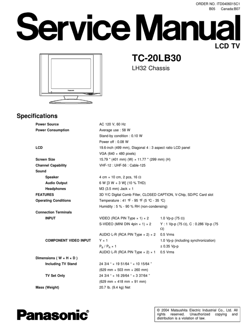
Card slot SD CARD slot × 1
OUTPUT VIDEO: RCA PIN Type × 1 1.0 V [p-p] (75 ohm)
UDIO L-R: RCA PIN Type × 2 0.5 V [rms]
DIGITAL AUDIO OUT PCM/Dolby Digital, Fiber Optic
FEATURES 3D Y/C Digital Comb Filter, CLOSED CAPTION, V-Chip
HDMI (HDAVI Control 2)
Vesa compatible Photo Viewer
Dimensions (W × H × D)
Including TV stand 32.9 ” × 23.3 ” × 9.8 ” (836 mm × 592 mm × 248 mm)
TV Set only 32.9 ” × 21.3 ” × 4.2 ” (836 mm × 540 mm × 106.8 mm)
Weight 40.0 lb. (18.0kg) NET
Note:
Design and Specifications are subject change without notice. Weight and Dimensions shown are approximate.
CONTENTS
Page Page
2
TC-32LX700
