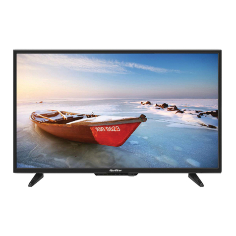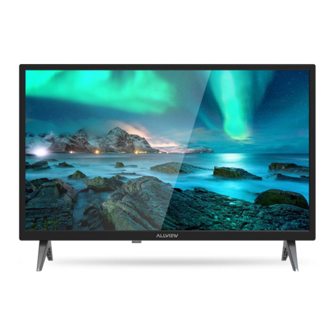
TH-43E410T TH-49E410T
2
TABLE OF CONTENTS
PAGE PAGE
1 Safety Precautions -----------------------------------------------3
1.1. General Guidelines ----------------------------------------3
1.1.1. Leakage Current Cold Check ----------------------3
1.1.2.
Leakage Current Hot Check (See Figure 1.)
-----3
2Warning--------------------------------------------------------------4
2.1. Prevention of Electrostatic Discharge (ESD)
to Electrostatically Sensitive (ES) Devices ----------4
2.2. About lead free solder (PbF) ----------------------------5
3 Service Navigation------------------------------------------------6
3.1. Service Hint--------------------------------------------------6
4 Specifications ------------------------------------------------------7
5 Service Mode -------------------------------------------------------9
5.1. How to enter into Service Mode ------------------------9
5.1.1. Purpose --------------------------------------------------9
5.1.2. Key command ------------------------------------------9
5.1.3. How to exit ----------------------------------------------9
5.1.4. Contents of adjustment mode ----------------------9
5.1.5. Display of SOS History----------------------------- 10
5.1.6. Exit ------------------------------------------------------ 10
5.1.7. Hotel Mode-------------------------------------------- 10
6 Troubleshooting Guide---------------------------------------- 11
6.1. Check of the IIC bus lines------------------------------ 11
6.1.1. How to access---------------------------------------- 11
6.1.2. Self-check indication only ------------------------- 11
6.1.3. Self-check indication and forced to factory
shipment setting ------------------------------------- 11
6.1.4. Exit ------------------------------------------------------ 11
6.1.5. Screen display --------------------------------------- 11
6.2. Power LED Blinking timing chart --------------------- 12
6.3. Method of detecting SOS ------------------------------ 12
6.4. LCD Panel test mode ----------------------------------- 13
6.5. No Power--------------------------------------------------- 13
7 Disassembly and Assembly Instructions --------------- 14
7.1. Speaker Ass’y (TH-43E410T)------------------------- 14
7.2. WIFI & LED Panel Ass’y (TH-43E410T) ----------- 15
7.3. PCB & AV Bracket Ass’y (TH-43E410T) ----------- 16
7.4. Vesa & Bottom Metal Ass’y (TH-43E410T)-------- 17
7.5. Label (TH-43E410T)------------------------------------- 18
7.6. Pop Sticker (TH-43E410T)----------------------------- 19
7.7. Fan Bag Ass’y (TH-43E410T) ------------------------ 20
7.8. Screw Fixing (TH-43E410T)--------------------------- 22
7.9. Pedestal Assembly (TH-43E410T) ------------------ 23
7.10. Bottom Back Cover and Bottom Corner Ass’y
(TH-43E410T)--------------------------------------------- 25
7.11. Bottom & Back Cover Ass’y (TH-43E410T) ------- 26
7.12. Back Cover Ass’y (TH-43E410T) -------------------- 27
7.13. Screw Installation (Panel) (TH-49E410T)---------- 28
7.14. Key Button & LED Assembly (TH-49E410T)------ 29
7.15. Side AV Bracket (TH-49E410T) ---------------------- 30
7.16. Felt Sticking (TH-49E410T)---------------------------- 32
7.17. Vesa Metal & BTM Back Cover (TH-49E410T)--- 33
7.18. Label Installation (TH-49E410T) --------------------- 34
7.19. Pop Sticker Labelling (TH-49E410T)---------------- 35
7.20. Accessories Assy (TH-49E410T) ------------------- 36
7.21. Pedestal Assembly (TH-49E410T) ------------------ 37
7.22. Screw Installation (BC) (TH-49E410T) ------------- 39
8 Measurements and Adjustments -------------------------- 40
8.1. Voltage chart of A-board-------------------------------- 40
8.2. Voltage chart of P-board ------------------------------- 40
9 Block Diagram --------------------------------------------------- 41
9.1. Main Block Diagram------------------------------------- 41
10 Wiring Connection Diagram -------------------------------- 42
10.1. Wire Dressing (TH-43E410T) ------------------------ 42
10.2. Wire Dressing 1 (TH-49E410T) ---------------------- 43
10.3. Wire Dressing 2 (TH-49E410T) ---------------------- 44
11 Schematic Diagram -------------------------------------------- 45
12 Printed Circuit Board------------------------------------------ 61
13 Exploded View and Replacement Parts List----------- 66
