Installation Guide
Note to the installer
LBefore attempting to connect or operate this product, please read the label on the rear of
the main monitor.
L
Please read this guide carefully, and install the product safely and correctly by following the
instructions. Carefully read the information found in the section titled "For your safety" in particular.
LOnly use attachments/accessories specified by the manufacturer.
LThe installation shall be carried out in accordance with all applicable installation rules.
LPanasonic assumes no responsibility for injuries or property damage resulting from
failures arising out of improper installation or operation inconsistent with this guide.
Additionally, any resulting malfunction will not be covered under the warranty.
LPlease confirm the wiring schematic diagram in this Installation Guide when you increase
an optional equipment.
LAfter installation, make sure to leave this guide with the customer.
Model Name Main Monitor Station
Model No. VL-MV26
Included accessories for installation
NFor the main monitor NPower supply unit and related items
Mounting
bracket × 1
Power supply unit
× 1
(Part No. VL-PS240)
Screw × 2
(4 mm × 16 mm) Cable binder × 2 Screw × 2
(4 mm × 40 mm)
1006, Oaza Kadoma, Kadoma-shi, Osaka 571-8501, Japan
http://www.panasonic.com
© Panasonic Corporation 2016
PNQW5093WA C0416HH2037
Main monitor station is described as
"main monitor" in this guide.
Main Monitor Station
VL-MV26
CAUTION
●If the wiring is underground, do not make any connections underground.
●If the wiring is underground, use a protection tube.
●If the wiring is outdoors, use a protection tube or a surge protector.
●Install the product securely adhering to the instructions in this guide to prevent it from
falling off the wall. Avoid installing onto low-strength walls, such as gypsum board, ALC
(autoclaved lightweight concrete), concrete block, or veneer (less than 18 mm thick) walls.
Preventing electric shock
Preventing injury
For your safety
To prevent severe injury and loss of life/property, read this section carefully before using the
product to ensure proper and safe operation of your product.
WARNING
Preventing fire, electric shock and short circuits
●Leave installation work to the dealer.
Installation work requires technique and experiences. Failure to observe this may
cause fire, electric shock, injury, or damage to the product. Consult the dealer.
●Electrical connection work should be performed by certified personnel only. Certification
is required for performing electrical connection work. Consult your dealer.
●Use only the specified power supply unit.
●Do not attempt to disassemble or modify this product. Contact an authorised service centre for repairs.
●Never install wiring during a lightning storm.
●Do not connect non-specified devices.
●Do not connect a power cable to a terminal that is not specified in this guide.
●When opening holes in walls for installation or wiring, or when securing the power cable,
make sure you do not damage existing wiring and ductwork.
●Do not make any wiring connections when the power supply is turned on.
●Do not use the supplied power supply unit for outdoor installations (it is for indoor use only).
●Do not install the main monitor and power supply unit in the following places:
- Places where the main monitor and power supply unit may be splashed with water or chemicals.
- Places where there is a high concentration of dust, or high humidity.
●Do not perform any actions (such as fabricating, twisting, stretching, bundling, forcibly bending,
damaging, altering, exposing to heat sources, or placing heavy objects on the power cable)
that may damage the power cable. Using the product with a damaged power cable may cause
electric shock, short circuits, or fire. Contact an authorised service centre for repairs.
●When existing chime wires are used, it is possible that they contain AC voltage. Contact
an authorised service centre.
Attach directly to a wall
Attach the power supply unit to the wall securely.
AScrews (accessory) × 2
Installing the main monitor
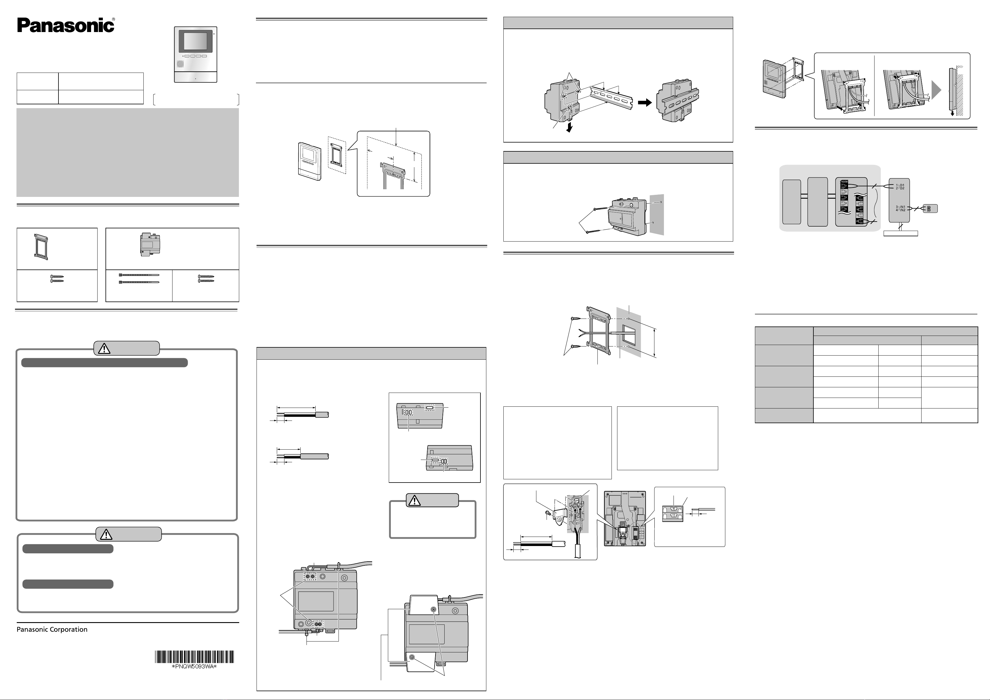
1 Attach the mounting bracket to the wall securely using the screws (4 mm × 16 mm).
●Install the mounting bracket on a vertical flat wall.
●Before drilling, refer to "Before installation" for installation location.
83.5 mm
Screws
Wall
Wire (Not included)
Mounting bracket
2 Connect the DC cable and wires.
●Connect the wires correctly according to "Wiring schematic diagram".
A Remove screw A and then remove the
terminal cover.
BPress the cable release button while
inserting the wires of the DC cable to the
terminal connectors (non-polar).
C Use the cable binder (accessory) to
secure the DC cable (double-coated
area) to the main monitor.
DMake sure to replace the terminal cover.
How to connect the DC cable:
While pressing on the button with a point-
ed object such as a screwdriver, insert
the wire into the terminal connector. (To
disconnect a wire, while pressing on the
button, pull out the wire.)
Important:
Do not connect the power cable.
(Damage may occur.)
How to make wiring connections:
Terminal cover
Screw A
Cable release button
50 mm or more
12 mm
9 mm
Button
Terminal
Attach to the DIN rail
Attach in the order described below so that hook (b) is positioned at the bottom.
1 Hang hook (a) on the DIN rail (A), and then pull and hold the lever down (B).
2 Secure hook (b) to the DIN rail (C).
Hook (a)
A
B
C
Hook (b)
Before installation
To avoid malfunction or communication disturbances, do not install the main monitor in the
following locations:
−Places where vibration or any other kind of impact occurs.
−Places where echoing is frequent.
−
Places near a high concentration of dust, hydrogen sulphide, ammonia, sulphur, or noxious fumes.
−Within 2 m of a TV, microwave, personal computer, air conditioner or any other electrical device.
Standard installation position of the main monitor
Place the main monitor in a location that your eyes are the same height as the centre of the display.
If a position of installation for the main monitor is specified
Install the mounting bracket to one of the following positions.
Position of installation for the main monitor
70 mm
64.5 mm
Note:
L
In areas surrounded by a high electrical field, disturbances may occur in the main monitor’s image or sound.
L
Do not place any objects within 20 cm of the main monitor. This may cause communication errors or malfunction.
LDo not install the main monitor inside a wall.
L
Do not install the main monitor in places where it will be affected by extremely high-frequency radio waves
(near broadcasting antennas etc.). This may cause the display to flicker or an interrupting noise to occur.
Installing the power supply unit
NAbout the installation location
●The device must be installed inside an electrical panel or cabinet.
●A readily accessible disconnect device shall be incorporated external to the equipment.
−External disconnect device must be certified and have a creepage and clearance distance of 3 mm or more.
NPrecautions for wiring
●Make sure you turn off the power at the breaker before performing any wiring work.
●Always connect AC or DC cables to the appropriate connection terminals. Incorrectly
connecting the AC or DC cables may damage the power supply unit.
●To prevent the power cables from disconnecting and to prevent electric shock, secure the
power cables using the cable binders (accessory) and attach the cable covers.
How to connect the power cable (AC/DC)
1 Strip the AC/DC cables as follows:
7 mm
45 mm
<AC cable>
<DC cable>
25 mm
7 mm
2 Remove the screws (B) and then remove
the cable covers (A).
3 Connect the AC/DC cable to the AC IN
terminal/DC OUT terminal on the top and
bottom of the power supply unit, and then
secure the wires by tightening the screws.
●Recommended torque:
−AC terminal: 0.5 N·m {5.1 kgf·cm}
−DC terminal: 0.45 N·m {4.6 kgf·cm}
<Front view>
AC cable
*1
DC cable
Screws
*1
Cable binders (accessory)
4 Use the cable binders (accessory) to
secure the AC/DC cables (double-coated
area) to the power supply unit.
5 Make sure to replace the cable covers (A).
Connect the power supply unit (accessory) and AC/DC cables (locally procured).
CAUTION
Insert the cables firmly all the way
into the terminals.
If the cables are not inserted all
the way, heat may be generated.
*1 Do not connect the AC cable and DC
cable inversely. That would be a cause
of malfunctions.
Make sure that there are no bare wires
exposed outside the product.
Screws (B)
Cable covers (A)
DC OUT terminal
AC cable
binder hole
AC IN terminal
<Top view>
<Bottom view>
DC cable
binder hole
Power supply unit (with cable covers
removed)
3 Mount the main monitor to the mounting bracket.
3-1 Line up the tab on the bottom of the bracket with the groove on the main monitor (A).
3-2 Line up the tab on the top of the bracket with the groove on the main monitor, and
push the main monitor down until it is secure (B).
Wall
Wiring schematic diagram
Set up correctly according to the following wiring schematic diagram and "Wire type and
length".
Lobby
Station
Control
Box
Distribution Box
Main Monitor
(up to 20 per Distribution box)
Door Bell
or
Emergency
Call Button
POWER SUPPLY UNIT
NP: Non-polarised
Connecting an optional lobby station for apartment complexes
Be sure to perform the following to ensure proper operation:
●Connect terminal D1/D2 on the main monitor with terminal D1/D2 on the distribution box.
Connecting a door bell
●Connect terminal IN1/IN2 on the main monitor with a door bell.
Note:
LThe door bell wiring schematic diagram is only an example. Refer to the wiring instructions
provided with your door bell.
Wire type and length
Wiring run
Wire type*1
Diameter Length (Max.)
Distribution box –
Main monitor
0.65 mm 22 AWG approx. 100 m
1.2 mm 17 AWG approx. 200 m
Main monitor –
Power supply unit
0.65 mm 22 AWG approx. 10 m
2 mm 12 AWG approx. 20 m
Power supply unit –
AC power source
1.2 mm 17 AWG
No requirement
2 mm 12 AWG
Main monitor –
Door bell*2
0.5 mm - 1.2 mm
(24 AWG - 17 AWG)
According to specification of
connected device.
*1 Note the following when selecting wiring
●Use 2-conductor (solid copper) wiring with a PE (polyethylene)-insulated PVC jacket.
Mid-capacitance, non-shielded cable is recommended.
●A certified power supply wiring has to be used with this equipment. The relevant national
installation and/or equipment regulations shall be considered. A certified power supply
wiring not lighter than ordinary polyvinyl chloride flexible wiring according to IEC 60227
shall be used.
*2 When using a door bell, select a device that meets the following guidelines:
●Connection device for option input (A contact) terminal (IN1/IN2):
−Input method: No-voltage contact
−Open-circuit voltage between terminals: DC 5 V or less
−Detection definite time: 0.1 second or more
−Short-circuit between terminals: 5 mA or less
−Resistance value: make: 500 Ωor less, break: 15 KΩor more


