manuals.online logo
Brands
  1. Home
  2. •
  3. Brands
  4. •
  5. Panasonic
  6. •
  7. Monitor
  8. •
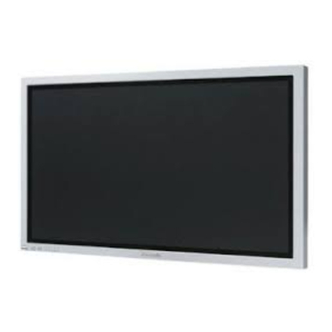
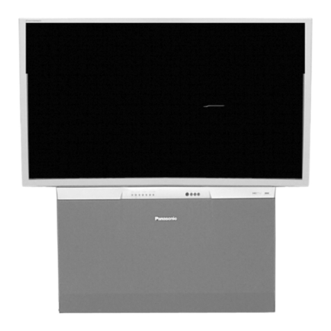
  9. Panasonic TH-42PW5 User manual

Panasonic TH-42PW5 User manual

Other manuals for TH-42PW5

3

This manual suits for next models

3

Other Panasonic Monitor manuals

Panasonic BT-LH1710 - Professional - LCD Production... User manual

Panasonic

Panasonic BT-LH1710 - Professional - LCD Production... User manual

Panasonic TH-65PF20W User manual

Panasonic

Panasonic TH-65PF20W User manual

Panasonic PT-56LCX70 - 56" Rear Projection TV User manual

Panasonic

Panasonic PT-56LCX70 - 56" Rear Projection TV User manual

Panasonic TH-103PF10UK - 103" Plasma Panel User manual

Panasonic

Panasonic TH-103PF10UK - 103" Plasma Panel User manual

Panasonic TH152UX1 - 152" PLASMA TV User manual

Panasonic

Panasonic TH152UX1 - 152" PLASMA TV User manual

Panasonic TH-42PHW5BX User manual

Panasonic

Panasonic TH-42PHW5BX User manual

Panasonic TH-75BQE1 User manual

Panasonic

Panasonic TH-75BQE1 User manual

Panasonic TH-50PF30U User manual

Panasonic

Panasonic TH-50PF30U User manual

Panasonic TY-SP65P7W-K User manual

Panasonic

Panasonic TY-SP65P7W-K User manual

Panasonic Viera TH-42PHD5 User manual

Panasonic

Panasonic Viera TH-42PHD5 User manual

Panasonic TH-80SF2HU User manual

Panasonic

Panasonic TH-80SF2HU User manual

Panasonic WV-LC1700 User manual

Panasonic

Panasonic WV-LC1700 User manual

Panasonic TH-37PG9W User manual

Panasonic

Panasonic TH-37PG9W User manual

Panasonic TH-47LF30ER User manual

Panasonic

Panasonic TH-47LF30ER User manual

Panasonic TH-65PF12EK User manual

Panasonic

Panasonic TH-65PF12EK User manual

Panasonic TH-55LFV5U User manual

Panasonic

Panasonic TH-55LFV5U User manual

Panasonic TH-50PM50U User manual

Panasonic

Panasonic TH-50PM50U User manual

Panasonic TH-42LF8U User manual

Panasonic

Panasonic TH-42LF8U User manual

Panasonic TH-55LFV50U User manual

Panasonic

Panasonic TH-55LFV50U User manual

Panasonic TH-47LFT30W User manual

Panasonic

Panasonic TH-47LFT30W User manual

Panasonic BTLH1800 - LCD HD MONITOR User manual

Panasonic

Panasonic BTLH1800 - LCD HD MONITOR User manual

Panasonic WV-CM1480 User manual

Panasonic

Panasonic WV-CM1480 User manual

Panasonic PT-40LC12 User manual

Panasonic

Panasonic PT-40LC12 User manual

Panasonic TH-47LF6W User manual

Panasonic

Panasonic TH-47LF6W User manual

Popular Monitor manuals by other brands

Samsung ME32C user manual

Samsung

Samsung ME32C user manual

ViewSonic VA926-LED user guide

ViewSonic

ViewSonic VA926-LED user guide

Furuno Mu 120c Operator's manual

Furuno

Furuno Mu 120c Operator's manual

Asus VB171D - 17" LCD Monitor Service manual

Asus

Asus VB171D - 17" LCD Monitor Service manual

AOC 9GLR Technical specifications

AOC

AOC 9GLR Technical specifications

DMG RAFFAELLO manual

DMG

DMG RAFFAELLO manual

AOC LM720 - 17" Technical specifications

AOC

AOC LM720 - 17" Technical specifications

Sony Trinitron GDM-F500 Service manual

Sony

Sony Trinitron GDM-F500 Service manual

Memorex MT1701 user guide

Memorex

Memorex MT1701 user guide

ViewSonic VE510s-4 Service manual

ViewSonic

ViewSonic VE510s-4 Service manual

Farenheit T-1503CM instruction manual

Farenheit

Farenheit T-1503CM instruction manual

Ditel DINOS DN129/AT Quick installation guide

Ditel

Ditel DINOS DN129/AT Quick installation guide

Sony SDM-S51 Specifications

Sony

Sony SDM-S51 Specifications

Kenwood DMX1025BT quick start guide

Kenwood

Kenwood DMX1025BT quick start guide

Dell S2409WFP user guide

Dell

Dell S2409WFP user guide

EverFocus EN-7517E instruction manual

EverFocus

EverFocus EN-7517E instruction manual

Dell P3222QE user guide

Dell

Dell P3222QE user guide

LG 50PM1M -  - 50" Plasma Panel Service manual

LG

LG 50PM1M - - 50" Plasma Panel Service manual

manuals.online logo
manuals.online logoBrands
  • About & Mission
  • Contact us
  • Privacy Policy
  • Terms and Conditions

Copyright 2025 Manuals.Online. All Rights Reserved.

ORDERNO. ITD0207019C0
D10 Canada:B07
WidePlasmaDisplay
TH-42PW5/ TH-42PWD5 / TH-37PW5/ TH-37PWD5
GP5DChassis
SPECIFICATIONS
Specifications
PowerSource: AC120V50/60Hz(UY/UZversion)
AC220-240V50/60Hz
(ExceptUY/UZversion model)
PowerConsumption: 225 W (37 inch), 295 W (42 inch)
2.4W (stand-bycondition)
(UY/UZversion)
2.8W (stand-bycondition)
(ExceptUY/UZversion model)
0.9W (Poweroff condition)
(UY/UZversion model)
1.5W (Poweroff condition)
(ExceptUY/UZversion model)
Plasma Displaypanel:Drivemethod ACtype
16:9aspectratio
ContrastRatio 3000:1
Screen size: 818 mm (W)×461 mm (H)
939 mm (diagonal)(37 inch)
920 mm (W)×518 mm (H)
1,056 mm (diagonal)(42 inch)
No. ofpixels
408,960 (852 (W)×480 (H))
[2,556 ×480 dots]
Operating condition:
Temperature 34 °F -104 °F (0°C-40 °C)
1
Humidity 20 %-80 %
Horizontal scanning frequency15.6-
110kHz
Vertical scanning frequency48 -120Hz
Connection terminals:
AV
Video in 1.0Vp-p (75-ohm)
S-VIDEOIN/ (MINI DIN
4PIN) Y:1Vp-p (75-ohm), C:0.286 Vp-p
(75-ohm)
AUDIOIN/ (RCAPIN
JACK ×2) 0.5Vrms (high impedance)
COMPONENT/RGB
Y/G 1.0Vp-p/composite(75-ohm)
0.7Vp-p/non-composite(75-ohm)
PB/B 0.7Vp-p (75-ohm)
PR/R 0.7Vp-p (75-ohm)
HD 1.0-5.0Vp-p (high impedance)
VD 1.0-5.0Vp-p (high impedance)
AUDIOIN
(RCAPINJACK×2) 0.5Vrms (high impedance)
PC
(HIGH-DENSITY
D-SUB15PIN) R,G,B/0.7Vp-p (75-ohm)
HD, VD/1.0-5.0Vp-p (high
impedance)
AUDIOIN(M3JACK) 0.5Vrms (high impedance)
SERIAL
EXTERNAL CONTROL
TERMINAL (D-SUB9PIN) RS-232CCOMPATIBLE
SPEAKERS(External
speakers)(6 ) 16W [8W+8W](10%THD)
Dimensions(W×H×D):920 mm ×550 mm 89 mm)(37 inch)
1,020 mm ×610 mm 89 mm)(42 inch)
Weight(Mass) approx. 24.0kg net(main unitonly)(37
inch)
approx. 28.2kg net(with speakers)(37
inch)
approx. 28.0kg net(main unitonly)(42
inch)
approx. 32.2kg net(with speakers)
(42inch)
2002 Matsushita ElectricIndustrial Co., Ltd. All rights reserved.
Unauthorizedcopying and distribution isaviolation oflaw.
2
1. Applicablesignals
2. SafetyPrecautions
2.1. General Guidelines
1. Whenservicing, observetheoriginal leaddress. Ifashortcircuit
isfound, replace all parts whichhavebeenoverheatedor
damagedbytheshortcircuit.
2. Afterservicing, see toitthat all theprotectivedevices suchas
insulation barriers, insulation papersshieldsareproperlyinstalled.
3. Afterservicing, make thefollowing leakagecurrentchecks to
preventthecustomerfrombeing exposedtoshock hazards.
2.1.1. LeakageCurrentColdCheck
1. Unplug theACcordand connect ajumperbetweenthetwoprongs
on theplug.
2. Measuretheresistance value, withanohmmeter, betweenthe
3
jumperedACplug and eachexposedmetalliccabinet parton the
equipmentsuchas screwheads, connectors, control shafts, etc.
Whentheexposedmetallicparthas areturnpathtothechassis,
thereading shouldbebetween1M and 5.2M . / Whenthe
exposedmetal does nothaveareturnpathtothechassis, the
reading must be . Figure1
2.1.2. LeakageCurrentHotCheck (See Figure 1 .)
1. Plug theACcorddirectlyintotheACoutlet. Donotuse an
isolation transformerforthischeck.
2. Connect a1.5k , 10 watts resistor, inparallel witha0.15 F
capacitors, betweeneachexposedmetallicparton theset and a
good earthground suchas awaterpipe, as shownin Figure1.
3. Use anACvoltmeter, with1000 ohms/voltormoresensitivity, to
measurethepotential across theresistor.
4. Check eachexposedmetallicpart, and measurethevoltageat
eachpoint.
5. Reverse theACplug intheACoutlet and repeat eachoftheabove
measurements.
6. Thepotential at anypointshouldnotexceed0.75 volts RMS. A
leakagecurrenttester(Simpson Model 229 orequivalent) maybe
usedtomake thehotchecks, leakagecurrentmust notexceed1/2
milliamp. Incase ameasurementisoutsideofthelimits specified,
thereisapossibilityofashock hazard, and theequipmentshould
berepairedand recheckedbeforeitisreturnedtothecustomer.
3. Prevention of ElectroStaticDischarge (ESD) to
ElectrostaticallySensitive(ES) Devices
Somesemiconductor (solidstate)devices canbedamagedeasilybystaticelectricity. Such
4
componentscommonlyarecalledElectrostaticallySensitive (ES)Devices. Examples oftypical
ES devices areintegratedcircuitsand somefield-effecttransistorsand semiconductor "chip"
components. Thefollowing techniques shouldbeusedtohelpreduce theincidence of
componentdamagecausedbyelectro staticdischarge(ESD).
1. Immediatelybeforehandling anysemiconductorcomponentor
semiconductor-equippedassembly, drainoff anyESDon your
bodybytouching aknownearthground. Alternatively, obtainand
wearacommerciallyavailabledischarging ESDwrist strap,
whichshouldberemovedforpotential shock reasonspriorto
applying powertotheunitundertest.
2. Afterremoving anelectrical assemblyequippedwithES devices,
place theassemblyon aconductivesurface suchas alminumfoil,
topreventelectrostaticchargebuildup orexposureofthe
assembly.
3. Use onlyagrounded-tipsoldering iron tosolderorunsolderES
devices.
4. Use onlyananti-staticsolderremoval device. Somesolder
removal devices notclassifiedas "anti-static(ESDprotected)"can
generate electrical chargesufficienttodamageES devices.
5. Donotuse freon-propelledchemicals. These cangenerate
electrical charges sufficienttodamageES devices.
6. DonotremoveareplacementES device fromits protective
packageuntil immediatelybeforeyou arereadytoinstall it. (Most
replacementES devices arepackagedwithleadselectrically
shortedtogetherbyconductivefoam, alminumfoil or
comparableconductivematerial).
7. Immediatelybeforeremoving theprotectivematerial fromthe
leadsofareplacementES device, touchtheprotectivematerial to
thechassisorcircuitassemblyintowhichthedevice will be
installed.
Caution
Besureno powerisappliedtothechassisorcircuit, and observe
all othersafetyprecautions.
8. Minimizebodilymotionswhenhandling unpackagedreplacement
ES devices. (Otherwise hamless motion suchas thebrushing
5
togetherofyourclothes fabricorthelifting ofyourfootfroma
carpetedfloorcangenerate staticelectricity(ESD)sufficient
todamageanES device).
4. About lead free solder(PbF)
Note:Leadislistedas (Pb)intheperiodictableofelements.
Intheinformation below, Pbwill refertoLeadsolder, and PbF will refertoLeadFree Solder.
TheLeadFree Solderusedinour manufacturing process and discussedbelowis(Sn+Ag+Cu).
ThatisTin(Sn), Silver(Ag)and (Cu)although othertypes areavailable.
Thismodel uses PbFree solderinit’smanufactureduetoenvironmental conservation issues.
For service and repairwork, we’dsuggesttheuse ofPbfree solderas well, although Pbsolder
may beused.
PCBsmanufacturedusing leadfree solderwill have thePbF withinaleafSymbol
stampedon theback ofPCB.
Caution
-Pbfree solderhas ahighermelting pointthanstandardsolder.
Typicallythemelting pointis50 ~70 °F(30~40 °C)higher. Please
use ahigh temperaturesoldering iron and set itto700 ±20 °F(370
±10 °C).
-Pbfree solderwill tend tosplashwhenheatedtoo high (about1100
°For600 °C).
Ifyou must use Pbsolder, please completelyremoveall ofthePb
free solderon thepinsorsolderarea beforeapplying Pbsolder. If
thisisnotpractical, besuretoheat thePbfree solderuntil itmelts,
beforeapplying Pbsolder.
-Afterapplying PbF soldertodoublelayeredboards, please check
thecomponentsideforexcess solderwhichmayflow ontothe
opposite side. (see figurebelow)
6
SuggestedPbfree solder
Thereareseveral kindsofPbfree solderavailablefor purchase. Thisproductuses Sn+Ag+Cu
(tin, silver, copper)solder. However, Sn+Cu(tin, copper), Sn+Zn+Bi (tin, zinc, bismuth)soldercan
alsobeused.
5. PCB Structuresheet of GP5Dchassis
7
Board Name Function Remarks
D1 FormatConverter 1
D2 PlasmaAISub-FieldProcessor 1
ZAudioout
SS SustainOut 1
SC Scanout 1
SU Sustainconnection (Upper) 1
SD Sustainconnection (Lower) 1
C1 DataDrive (LowerRight)
C2 DataDrive (LowerLeft)
H3 Speakerterminal
S1 Powerswitch
SS2 Sustainconnection (Upper)
SS3 Sustainconnection (Lower)
V1 FrontSW. &Remotereceiver
FLinefilter
PPowersupply 1
HX PC_type_Inputterminal
HY BNC_type_Inputterminal 2
HZ RCAtype_Inputterminal 3
Remarks
1. Recommend PCB'sforinitial service forGP5Dchassis.
2. ForSystemmodel exceptBX, EX version
3. ForConsumermodel exceptBX, EX version
6. Service Hint
8
7. Location of Lead Wiring
9
8. Adjustment Procedure
8.1. +B Set-up
8.1.1. Item/ Preparation
1. InputaGreyscalesignal.
10