2-4
PANASONICREMOTEEVRADJUSTMENTSYSTEM(C)MCICo.CCTVPRODUCT:CF224EEPROM:0
✽ ✽ ✽ ✽ ✽ ✽ ✽ ✽ ✽ ✽ ✽ ✽ ✽ ✽ ✽ ✽ ✽ ✽ ✽ ✽ ✽ ✽ ✽ MENU ✽ ✽ ✽ ✽ ✽ ✽ ✽ ✽ ✽ ✽ ✽ ✽ ✽ Page(1/1)✽ ✽ ✽ ✽ ✽ NTSC
1.FSCADJUSTMENT
3.ALCLEVEL
4.AGCOFFGAIN
5.1.OBLEVEL
5.2.VIDEOOUTGAIN
5.3.OBCONFIRM
6.BURSTLEVEL
7.1.3200KRGAIN
7.2.3200KBGAIN
7.3.3200KPHASE
7.5.COLORCENTERPOINTADJUSTMENT
8.1.ATWCONFIRM
8.2.HILIGHTCHROMACLIP
<CONTENTS> IC5-3PIN[CCD]28.63636MHz+-40Hz
<INSTRUCTION>PLEASECHOOSEMENUDATABYARROW-KEY
LOAD(F1) QUIT(F3) SAVE(F5)
Table 4-1
8Press the SAVE (F5) key of the Computer, then the
Computer will ask you for the file name.
8Type xxxxxxxx.EVR. Give an appropriate file name for
xxxxxxxx within 8 letters, but do not use CF224P.
8Press the ENTER key.
8This saving procedure is recommended to keep the cur-
rent adjustment status of the Camera.
8Press the LOAD (F1) key and type CF224P.EVR and
press the ENTER key for presetting adjustment of the
Camera.
8Press the ENTER key to start adjustment.
4.2. Adjustment Procedure-2
(E.V.R. Adjustment)
8Insert new disk containing the E.V.R. Adjustment pro-
gram into IBM PC/AT and turn on the Power Switch of
IBM PC/AT.
8When starting an adjustment, at the prompt, type
LADJ CF224P and press the ENTER key, an initial menu
will be displayed in Table 4-1.
4. Adjustment Procedure
8Refer to the Wiring Diagram on page 3-1.
4.1. Adjustment Procedure-1
(1). Line Lock VCO Adjustment
Test Point: TP1 (LL VCO) Main Board
Adjust: L301 (LL VCO) Sensor Board
8Set the Synchronization Mode Selector (on the SW Board
SW1) to LL position.
8Connect the Digital Voltmeter to TP1.
8Adjust L301 so that the voltage becomes 1.65 V ± 0.35 V.
8Return the Synchronization Mode Selector (on the SW
Board) SW1 to INT position.
(2). Flange-back Adjustment
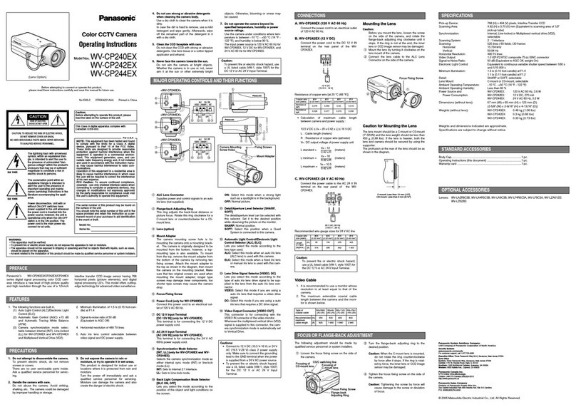
Test Point: Video Output Connector
Adjust: Flange-back Adjusting Cam
8Referring to Fig. 4-1, loosen the Zoom Lock Screw at the
tip of the Zoom Lever.
8Move the Zoom Lever to TELE side fully.
8Loosen the Focus Lock Screw at the tip of the Focus
Lever.
8Move the Focus Lever to FAR side fully.
8Set the Radiation Chart.
8Aim the Camera at the Radiation Chart 10m away.
8Loosen the Flange-back Lock Screw that secures the
Flange-back Adjusting Cam.
8Adjust the Flange-back Adjusting Cam to obtain best
focal point.
Focus Lever
(Focus Lock Screw)
Zoom Lever
(Zoom Lock Screw)
Flange-back
Adjusting Cam
Flange-back
Lock Screw
Fig. 4-1
8Move the Zoom Lever to WIDE side fully.
8Confirm that the focal point can be obtained by moving
the Focus Lever.
8Tighten the Flange-back Lock Screw that secures the
Flange-back Adjusting Cam carefully.
8Tighten the Zoom Lock Screw at the tip of the Zoom
Lever carefully.
8Tighten the Focus Lock Screw at the tip of the Focus
Lever carefully.
NEAR
WIDE
FAR
TELE

