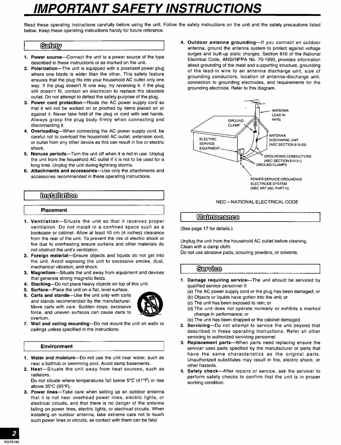
Panasonic SAHE70 - RECEIVER User manual
Other Panasonic Stereo Receiver manuals

Panasonic
Panasonic HDMI SA-XR70E User manual

Panasonic
Panasonic RF-SW150 User manual

Panasonic
Panasonic SA-XR15E User manual

Panasonic
Panasonic VIERA SA-BX500EB User manual

Panasonic
Panasonic SA-DT300E User manual

Panasonic
Panasonic SAHT280 - RECEIVER User manual

Panasonic
Panasonic SA-XR55E User manual

Panasonic
Panasonic SAHE200 - RECEIVER User manual

Panasonic
Panasonic SADA15 - RECEIVER User manual

Panasonic
Panasonic SAHT270 - RECEIVER User manual

Panasonic
Panasonic SA-XR10E User manual

Panasonic
Panasonic CQ-LA1923L Building instructions

Panasonic
Panasonic SAHT210 - RECEIVER User manual

Panasonic
Panasonic SAHT220 - RECEIVER User manual

Panasonic
Panasonic SA-DT300E User manual

Panasonic
Panasonic SA-XR55E User manual

Panasonic
Panasonic Technics SA-800 User manual

Panasonic
Panasonic SA-DT310E User manual

Panasonic
Panasonic RF-U700 User manual

Panasonic
Panasonic SAHE200 - RECEIVER User manual


Popular Stereo Receiver manuals by other brands


Pioneer
Pioneer SX-1000TA operating instructions

Yamaha
Yamaha MusicCast TSR-5B3D owner's manual

Sony
Sony STR-DE335 - Fm Stereo/fm-am Receiver operating instructions

Sony
Sony STR-DG500 - Multi Channel Av Receiver Service manual

Pioneer
Pioneer SX-838 Service manual

Sherwood
Sherwood S-2660CP operation instruction