manuals.online logo
Brands
  1. Home
  2. •
  3. Brands
  4. •
  5. Panasonic
  6. •
  7. Stereo System
  8. •
  9. Panasonic DoubleFeature PV-D4753S User manual

Panasonic DoubleFeature PV-D4753S User manual

UaLt EATURE Panasonic"
(3k'ni-/vIBl(]n
DVD/VCR DECK
Operating Instructions
Model No. PV-D4753S
Connections and Initial Setup Procedures are on pages 12 to 17. I
DtGl_
nn[:_# pq-tIp
DIGITAL 5UKROUND
_lUllO_Ipmo
MULTI FORMAT PLAYBACK
_¢Ability t_ #_Y back may depend on recording condilJons
As an ENERGY STAFf _Partner, Matsushita Electric Corporation
of America has determined that this product or product model
meets the ENERGY STAR @guidelines for energy efficiency,
Please read these instructions carefully before attempting to connect, operate or adjust thi
product. Ptease save this manuat.
Spanish Quick Use Guide is included+
(Gu(a para T_pida consutta en espa6o[ est6 incluida+) LSQT067
Important Safeguards and Precautions
FrFORYOURSAFETY'READANDRETAINALLSAFETY I OUTDOOR ANTENNA INSTALLATION
AND OPERATING INSTRUCTIONS. HEED ALL 1 SAFEANTENNA AND CABLE CONNECTION
ARNINGS IN THE MANUAL AND ONTHE UNIT ff an outside antenna or cable system is connected to the
I INSTALLATION I
1 POWER SOURCECAUTION
Operate only from a power source indicated on the
unit or in this manual, ff necessary, have y,our
Electric Utility Service Company or Video Products
Dealer verity the power source in your home.
g POLARIZEDOR GROUNDING PLUG
As a safety feature, this product comes with either
a polarized power cord p_ug (one blade is wider
than the other), or a three-wire grounding type plug.
POLARIZED PLUG CAUTION:
This plug wil_only f_ into an ou_etone way. _tyou cannot
fully insert the plug, try reversing it. If it st_llwill not fit,
have a_ electrician instal_the proper wal_OLdJebDO not
defeat the safety feature by tampering with the p_ug.
GROUNDING PLUG CAUTION:
This plug wil_ only fit into a three-hole grounding
out_et. _Inecessary, have an electrician instal_ the
proper outlet. DO not defeat the safety feature by
tampering with the plug.
3 POWER CORD
Make sure power cords are routed so that they
are not _ikely to have anything rest on them, roll
over them, or be in the way of walking tragic.
If an extension cord is used, make sure it also
has either a polarized or grounded plug and that
the cords can be securelvconnected.
Frayed cords, damaged plugs, and damaged or
cracked wire insulation are hazardous and should
be replaced by a qualified service technician.
Overloaded outlets and extension cords are fire
hazards and should be avoided.
4 DO NOT BLOCK VENTILATION HOLES
Ventitation openings in the cabinet release heat
generated during operation. _fthey are blocked,
heat build-up inside the unit can cause failures that
may result in a fire hazard or heat damage to
casseftes or discs.
For protection, foitow these ru_es:
a. Never cover ventilation slots or the unit while in
use, or operate the unit when placed on a bed,
sofa, rug, or other soft sudace.
b. Avoid built-in instaitation, such as a book case
or rack, unless proper ventilation is provided.
BPLACEMENT: AVOtD EXTREMELY HOT LOCATIONS
ORSUDDEN TEMPERATURE CHANGES
Do not place the unit over or near heater or
radiator, in direct sunlight, inside cthsed vehicles,
in high temperature [over t04°F (40°C)], or in over
75% humidity. If the unit is suddenly moved from
acold place to a warm one, moisture may
condense in the unit and on the tape causing
damage. Never subject the unit to vibration,
impact, or place it so that the sud_ce is fitted as
internal parts may be seriously damaged.
6 TO AVOID PERSONAL INJURY
•Do not place unsecured equipment on _ sloping
Surface.
• DO not place this unit on _ny support that is not
firm, level, and adequately strong A
The unit could fal_ causing seriou
injury to a child or adult and
damage to the unit.
• An appliance and cart
combination should be moved
with care. Quick stops,
excessive force, and uneven
sudaces may cause the appliance _nd cart
combination to overturn.
• Carefuity follow ait operating instructions and
use the manufacturer's recommended
accessories when operating this unit or
connecting it to any other equipment.
2
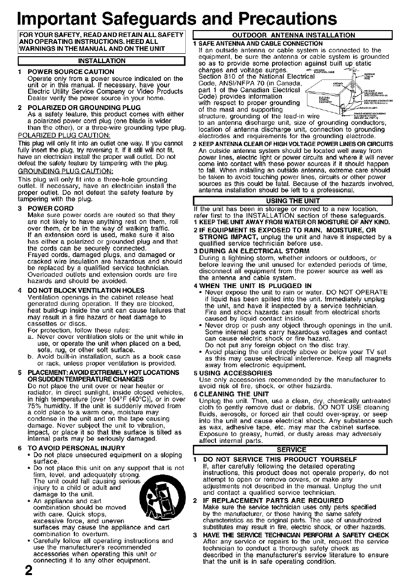
equipment, be sure the antenna or cable system is grounded
so as to provide some protection against built up static
charges and voltage surges. _. _,_ -
Section 810 of the National Electrical _,,_
Code, ANSI/NFPA 70 (in Canada, ca
part I of the Canadian Electrical _ _._,.,_%_,
Cede provides information _ /_f-_ ............
with respect to proper grounding _ _-_.j_,'_=.'="
of the mast and supporting .,=_ ......
structure, grounding of the lead-in wire _#_
to an _ntenna discharge unit, size of grounding conductors,
location of antenna discharge unit, connection to grounding
electrodes and requirements for the grounding electrode.
2 KEEPANTENNACLEAROF HIGHVOLTAGEPOWERLINESORCIRCUITS
An outside antenna system should be located welt away from
power lines, electric light or power circuits and where it will never
come into contact with these power sources if it should happen
to fall. When installing an outside antenna, extreme care should
be taken to avoid touching power lines, circuits or other power
sources as this could be fatal. Because of the hazards involved,
antenna installation should be left to a professional.
I USING THE UNIT I
If the unit has been in storage or moved to a new location,
refer first to the INSTALLATION section of these safeguards.
tKEEPTHE UNITAWAY FROM WATEROR MOISTUREOF ANY KIND,
2IF EQUIPMENT tS EXPOSED TO RAIN, MOISTURE, OR
STRONG IMPACT, unplug the unit and have it inspected by a
qualified service technician before use.
3 DURING AN ELECTRICAL STORM
During a lightning storm, whether indoors or outdoors, or
before leaving the unit unused for extended periods of time,
disconnect all equipment from the power source as well as
the antenna and cable system.
4 WHEN THE UNIT IS PLUGGED IN
•Never expose the unit to r_in or water. DO NOT OPERATE
if liquid has been spiited into the unit. _mmediately unplug
the unit, and have it inspected by a service technician.
Fire and shock hazards can result from electrical shorts
caused by liquid contact inside.
• Never drop or push any object through openings in the unit.
Some internal parts carry hazardous voltages and contact
can cause electric shock or fire hazard.
DO not put any foreign object on the disc tray.
• Avoid placing the unit directly above or below your TV set
as this may cause electrical interference. Keep _ll magnets
away from electronic equipment.
5 USING ACCESSORIES
Use only accessories recommended by the manufacturer to
avoid risk of fire, shock, or other hazards.
6 CLEANING THE UNIT
Unplug the unit. Then, use a clean, dry, chemicaity untreated
cloth to gently remove dust or debris. DO NOT USE cleaning
fluids, aerosols, or forced air that could over-spray, or seep
into the unit and cause electrical shock. Any substance such
as wax, adhesive t_pe, etc. may mar the cabinet surface.
Exposure to greasy, humid, or dusty areas may adversely
affect internal parts.
I SERVICE I
1 DO NOT SERVICE THIS PRODUCT YOURSELF
If, after carefully following the detaited operating
instructions, this product does not operate properly, do not
attempt to open or remove covers, or make any
adjustments not described in the manual. Unplug the unit
and contact a qualified service technician.
2IF REPLACEMENT PARTS ARE REQUIRED
Make sure the service technician uses only parts specified
by the manufacturer, or those havthg the same safety
characteristics as the edgina{ paris. The use of unauthorized
substitutes may result in fire, electric shock, or other hazards.
3 HAVE THE SERVICE TECHNICIAN PERFORM A SAFETY CHECK
After any service or repairs to the unit, request the service
technician to conduct a thorough s_fety check as
described in the manufacturer's service literature to ensure
that the unit is in s_fe operating condition.
Safety Precautions/Mesures de sdcuritd
WARNING: To prevent fire or shock hazard, do not expose this
equipment to rain or moisture.
CAUTION: To prevent electric shock, match wide blade of plug to
wide slot, fully insert.
Avertissement: Afin de pr_venir tout risque d'incendie ou de chocs
dlectriques, ne pas exposer cet appareil &la pluie ou
une humiditd excessive.
Attention: Pour _viter les chocs _lectriques, introduire la lame la
plus large de la fiche darts la borne correspondante de la
prise et pousser jusqu'au fond.
CAUTION: TOHEDUCE THE HISK OF ELECTR C SHOC}
£Q NOT RF_tOVE COVSR (OR BACK)
NO US_R-SERVLC_LE PA£TS _NS_I)E
£EFER SERViCInG TO QUALIFIED 9ERVICE PERSONN_
This symbol warns the user that uninsulated voltage
within the unit may have sufficient magnitude to cause
electric shock.
Therefore, it is dangerous to make any kind of contact
with any inside part of this unit.
This symbol alerts the user that important literature
concerning the operation and maintenance of this unit
has been included. Therefore, it should be read
carefully in order to avoid any problems.
CAUTION:
UNIT IS A CLASS I LASER PRODUCT.
HOWEVER THIS UNIT USES A VISIBLE LASER BEAM WHICH COULD
CAUSE HAZARDOUS RADIATION EXPOSURE IF DIRECTED.
BE SURE TO OPERATE THE UNIT CORRECTLY AS INSTRUCTED.
WHEN THIS UNIT IS PLUGGED TO THE WALL OUTLET, DO NOT PLACE
YOUR EYES CLOSE TO THE OPENING OF THE DISC TRAY AND OTHER
OPENINGS TO LOOK INTO THE INSIDE OF THIS UNIT.
USE OF CONTROLS OR ADJUSTMENTS OR PERFORMANCE OF
PROCEDURES OTHER THAN THOSE SPECIFIED HEREIN MAY RESULT IN
HAZARDOUS RADIATION EXPOSURE.
DO NOT OPEN COVERS AND DO NOT ATTEMPT TO REPAIR YOURSELF.
REFER SERVICING TO QUALIFIED PERSONNEL.
'CAUTION:
LASER RADIATION
WHEN OPEN DO NOT
STARE INTO BEAM.
ATTENTION:
I RAYONNEMENT
|LASER EN CAS
|D'OUVERTURE.
| NE PAS REGARDER
DANS LE FAISCEAU.
(Inside of product)
FCC NOTE:
This equipment has been tested and found to comply with part 15 of the FCC Rules. These limits are
designed to provide reasonable protection against harmful interference when operated in a residential
environment. If this equipment does cause interference to radio or television reception, which can be
determined by turning the equipment off and on, use the equipment in another location and/or utilize
an electrical outlet different from that used by the receiver.
If necessary, consult the dealer or an experienced radio/TV technician for help. The user may find the
booklet, "Something About Interference" available from FCC local regional offices helpfuh
FCC Caution:
To assure continued compliance, (example- use only shielded interface cables when connecting to
other devices.) Any changes or modifications not expressly approved by the party responsible for
compliance could void the user's authority to operate this equipment.
FCOWaming: Any unauthorized changes or modifications to this equipment would void the user's
authority to operate.
Region Management Information:
This DECK is designed and manufactured to respond to the
Region Management Information that is recorded on a DVD
disc. If the Region number described on the DVD disc does
not correspond to the Region number of this DECK, this
DECK cannot play this disc.
OThe Region number for this DECK is "1".
OThe Player will play DVD-Video marked with labels
containing "1" or "ALL".
IExample:
3
Congratulations
on your purchase of one of the most
sophisticated and reliable products on the
market today, Used properly, it will bring you
years of enjoyment. Please fill in the
information below. The serial number is on the
tag located on the back of your DECK.
• Date of Purchase
• Dealer Purchased From
• Dealer Address
• Dealer Phone No.
• Model No, PV-D4753S
• Serial No.
[] Remote Control
LSSQ0377 [] Batteries 2 "AA"
[] RF Coaxial Cable
LSJA0372
.le]Ft [LmI JIGT ]
To order accessories, call toll free
t-800-332-5368.
Disc formats supported by this DECK
DECK can play back discs bearing any of the followin
marks: [Discs Played 8cm (3") or 12cm (5"
Logo Disc type
_. _ DVD (DVD-Video)
DVD-R (DVD-Video formatted
discs [finalized])
.._=,o DVD-Audio
V,deoCO
CD (CD-DA)
[_"_ CD-R/CD-RW (CD-DA,Video CD
=,_,m formatted discs [finalized])
WMA, MP3, JPEG
Discs which cannot be played
• DVD with Region No. other than "1" or "ALL'
• PAL discs (the audio on DVD-Audio can be played),
DVD-RAM, DVD-ROM, DVD-RW, DVD+RW, CD-ROM,
CDV, CD-G, CVD, SVCD, SACD, Divx Video Disc and
Photo-CD
O
• Do not use irregularly shaped discs (e.g. heart-
shaped), as these can damage the unit.
• It may not be possible to play CO*R, CD-RW and
DVD*R in all cases due to the type of disc or
condition of the recording.
Handling precautions
• Sticking a label on the disc may impair DVD-R playback.
• Do not attach sticker to discs. (Do not use discs with
exposed adhesive from tape or left over peeled-off
stickers.)
• Only hold disc by edges as shown below. Fingerprints,
dirt and scratches can cause skipping and distortion.
• Do not write on label side of disc.
• Never use record cleaning sprays, benzine, thinner,
static electricity prevention liquids, or any other solvent.
1)_ Open cover.
2) nsert
batteries as
marked.
3) Close cover.
[] Battery replacement caution
•DO not mix old and new batteries.
• Do not mix alkaline with manganese
batteries.
• Do not try to close disc tray when
disc is not properly placed. _"
To clean disc surface /%
With a soft, damp (water only) cloth, gently O
wipe from the center hole to the outer edge_
as shown below. (Wiping in a circular
pattern will scratch the surface.) X
If disc is brought from a cold to a
warm environment, moisture may _ _._ _)
form on the disc
Wipe away moisture with a soft, dry, lint-free cloth
before using disc. (See above.)
Improper disc storage
Discs could be damaged if stored or left in areas:
• exposed to direct sunlight.
• that are humid or dusty.
• near heat (i.e. heater, radiator, etc.).
4
Important Safeguards and Precautions ............................ 2, 3
Before Using ............................................................................ 4
DECK & Cassette Information ........................................... 6,7
Location of Controls ....................................................... 8 ~ 10
Displays (On Screen Displays and Multi Function Display) .................... 1 1
Connections .................................................................. 12 ~15
Initial Setup for Basic Connections (Ready to Ptay) .......... t 6, t 7
Reset Language, Channels, Clock, VCR's Output Channel ... 18, 19
Playback/Record on a Tape ........................................... 20, 21
Basic DVD Operation ...................................................... 22, 23
Timer Recording .............................................................. 24, 25
MTS Broadcast/VHS Hi-Fi Stereo System .................... 26, 27
Multi-Brand Control Feature ........................................... 28, 29
Tape Operation (Search System) ....................................... 30 ~32
Special VCR Features ..................................................... 33, 34
Copying Your Tapes (Dubbing) ......................................................... 35
Disc Operation ............................................................... 36 ~41
DVD Operation using On-Screen Displays ................. 42 ~44
MP3/WMA/JPEG Playback Operation .......................... 45 ~47
DVD Lock Feature ................................................................. 48
Settings for DVD Operation .......................................... 49 ~53
Language Code List .............................................................. 54
Warning and Instruction Displays ........................................ 55
Before Requesting Service ............................................. 56, 57
Limited Warranty ............................................................. 58, 59
Customer Services Directory ............................................... 59
Spanish (Espa_ol) Quick Use Guide ............................. 60~ 65
Index ................................................................................. 66, 67
Playing older or damaged tapes may eventually
cause video heads to become clogged.
Video Head Clog Sensor
During playback, this
screen appears if WDEOHEADSMAY
clogging is detected. .EESCL£Ar_ING
_LEAS£ _NSER_ HEAD
To remove screen, CLEANINGCASSENE
OR REFER _O MANUAL
press PLAY on the
remote or DECK. E_ :_¥
• Use "dry" type heed cleaning cassette
only. (Part NO.NV-TCL30PT is recommended.)
• FolJow cleaning tape instructions carefully.
Excessive use of tape can shorten head life.
•If head clog symptoms persist, contact your
nearest servicenter by visiting our Web Site
(see p. 59).
Break off the tab to
prevent recording.
Record Tab
Screw driver j
To record again
Cover the hole
with cellophane tape.
Only use tapes with the _ mark in this DECK.
Tape Speed Type of Video Cassette
Setting T6O T120 T160
SP 2 Hours
Standard Play) fHour 2 Hours 40 Minutes
LP 2Hours 4 Hours 5Hours
(Long Play) 20 Minutes
SLP 3 Hours 6 Hours 8 Hours
(Super LongPlay)
Use a soft cloth or dusting attachment of a vacuum cleaner to remove dust from the ventilation holes
on the back sides and bottom of the cabinet. Plastic surfaces are easily scratched and can be
marred by alcohol and various solvents. Avoid excessive use of oil-based furniture polishes since
the materials used in the cabinet will accumulate more dust. We recommend using a non-abrasive,
antistatic cleaner and polisher.
Digital Auto Picture
Automatically controls the video output signal for less noise depending on the tape condition.
Digital Auto Tracking
Continuously analyzes the signal and adjusts for optimum picture quality.
Manual Tracking Control
(to reduce picture noise)
Use during Playback and Slow Motion mode to reduce picture noise.
Press CR (TRACKING) _ on the remote control or on DECK until the picture clears up.
To return to Auto Tracking, press POWER off, then on again a few seconds later.
V-Lock Control Lto reduce picture iitter'_
In Still mode, CH(TRACKIN(_) _ operate as a V-Lock control.
6
Power Source:
Power Consumption:
Video Signal:
Video Recording System:
Audio Track:
Tuner:
Broadcast Channels:
CABLE Channels:
Input/Output Terminal:
Input Terminal:
Output Terminal:
Operating Temperature:
_vPeerating Humidity:
ight:
Dimensions:
Discs Played
(t) DVD-Video Disc
DVD-Audio Disc
(2) Compact Disc
(CD-DA,VideoCD)
120 V AC, 60 Hz
Power On: Approx. 32 watts, Power Off: Approx. 4 watts
EIA Standard NTSC color
4 rotary heads helical scanning system
1 track (Normal), 2 channel (Hi-Fi Audio Sound)
VHF 2 - 13, UHF 14 ~ 69
Midband A through I (14 - 22), Superband J through W (23 - 36)
Hyperband AA ~ EEE 37 ~ 64), Lowband A-5 ~ A-1 95 - 99
Speca CABLE channe 5A 01 ,Utraband 65 - 94. 100 ~ 125
AudiolVideo Line Input/Output, RF Input/Output
Audio/Video Line Input (Front)
S-Video Output (DVD only), Component Video Output (DVD only)
Audio Output 2 (L), (R)
5 °C - 40 °C (4t °F ~104 °F)
10%-75%
4.9 kg (10.8 Ibs).
430 (W) x 95.5 (H) x 344 (D) mm
16-15/16" (W) x 3-12/16" (H) x 13-9/16" (D) inch
5" (12 cm) single-sided single-layer
5" (12 cm) single-sided double-layer
5" (12 cm) double-sided double-layer (one layer per side)
3" (8 cm) single-sided single-layer
3" (8 cm) single-sided double-layer
3" (8 cm double-sided double-layer one layer per side)
5" (12 crn dsc
3" (8 cm) disc
(CD-R/CD_RW,MP3,WMA,JPEG)
Digital Audio Output: Digital Optical Connector
Pickup: Wavelength: 655 nm (DVD), 790 nm (Video CD/CD)
Laser power: CLASS II
Note: • Designs and specifications are subject to change without notice.
II- Ol • •[_
Angle: Some DVD discs feature scenes simultaneously shot from different angles.
The ANGLE button can be used to view the scene from different angles.
(ANGLE Indicator lights on DECK when a scene recorded at different
angles is detected.)
Chapter Number:Titles are subdivided into numbered sections. You can quickly search for
a favorite scene using these numbers.
DVD: A high-density optical disc on which high-quality pictures and sound have
been digitally recorded. DVD incorporates new video compression
technology (MPEG II) and high-density recording technology which allow
entire movies to be recorded with incredible playback quality.
Playback Control:With Video CD (version 2.0), scenes or information may be selected for
viewing or listening from an interactive menu that appears on the TV screen.
Subtitles: Written dialogue which appears at the bottom of the screen.
Time Number: The elapsed play time from the start of a disc or title. Use to quickly find
scenes. (May net work with some discs.)
Title Numben For DVD discs with two or more tit_es,the title is numbered as fitte f, title 2, etc.
Track Number: Numbers assigned to tracks on Video CDs and CDs to allow specific tracks
to be quickly located.
Video CD: CD containing picture and sound with same quality level as video tape.
This DECK also supports Video CDs with playback control (version 2.0).
Apparatus Claims of U.S. Patent Nos. 4,631,603, 4,577,216 4819098 and 4,907,093,
censed for mited viewing uses only.
This product incorporates copyright protection technology that is protected by method claims of
certain U.S. Patents and other intellectual property rights owned by Macrovision Corporation and
other rights owners. Use of this copyright protection technology must be authorized by Macrovision
Corporation, and is intended for home and other limited viewing uses only unless otherwise
authorized by Macrovision Corporation. Reverse engineering or disassembly is prohibited. 7
[_ei_";J._ILeJl LeJl L_eJIL_eJlL_J
EJECT /
OPEN /CLOSE
pp. 20, 22
POWER
VCR mode
p. 28
DSS /CABLE mode
p. 28
PLA Y
pp. 20, 22
REWIND
SLOW-
pp. 20, 23
VCR/TV
p. 21
NUMBER keys
RETURN/SEARCH _
pp. 22,30
ACTION
pp. 18, 49
SKIPI4NI
p,_
p, 38
Bold: VCR Function
Italic: DVD Function
Bold Italic: VCR and DVD Functions
Normal: Others DISPLAY
p. 11, 42
JTV mode
p, 28
DVD mode
p. 28
INPUT
p. 35
FAST FORWARD /
SEARCH/SLOW+
pp. 20, 23
_PAUSE / STILL
pp. 20, 23
STOP
pp. 20 22
ADD/DELETE /CLEAR
pp. 19, 39, 48
\Virtual Surround Sound (V.S.S.) /
ENTER
pp. 23, 28
PROGRAM
p. 24
SELECT
AV< I_
MENU
p, 38
SET
ANGLE
p, 37
A UDIO
pp. 27,
SUB TITLE
p. 36
ZOOM
p, 37
_COMMERCIAL SKIP /
ZERO SEARCH
pp. 31, 32
VOLUME 4.- /
p. 28
COU
RESET
p. 32
SPEED / PAGE
p. 21, 41
CHANNEL •/•
TRACKING /V-LOCK
pp. 6, 21
--TAPE POSITION /
VOLUME ADJUST
p. 34, 40
EJECT button: When this button is pressed in VCR mode, the tape is ejected.
This button is inoperative if pressed during recording.
If pressed in DVD mode, the disc tray opens or closes.
RECORD
p. 21
8
m i _H illfJ[_v_vlo)m I]=[@J[_
Bold: VCR Function
Italic: DVD Function
Bold Italic: VCR and DVD Functions
Normal: Others
STOP/EJECT
p. 20
FAST FORWARD/SEARCH
p. 20
PLAY
p. 20
REWIND/SEARCH
p. 20
Remote
Input Connector 2
(LINE 2) p. 35
CHANNEL _IJV
TRACKING/V-LOCK
pp. 6, 21
REC
p. 21
If the disc cannot be removed...
First, unplug DECK. Then, prepare a rigid
wire (e.g. an extended paper clip) and,
applying moderate force, insert it straight
into the hole at the base of the tray.
The tray will eject a little. Now, pull the tray
all the way out and remove the disc.
Over 2 inches
Cassette Disc Tray p. 22
Multi Function
Display
p. ll
;IVE
p. 10
PAUSE
p. 23
SKIPII_I
SKIP p. 23
PLA Y
p. 22
STOP
p. 22
Use when moving DECK to new location, or if a mistake was made in the initial
Setup section (return to Factory Setting).
• Make sure a tape is not inserted in the DECK.
i i
11! '1 r 1
2
] Turn DECK Power on.
O Press and hold both VCR PLAY
<i and CHANNEL • on the DECK for
more than 5 seconds.
• The power shuts off.
Do "initial Setup (Ready to Play)"
on page 16. 9
_'. " i • I I']_=I
AC Power Plug
•While plugged into an AC outlet,
this DECK consumes 4 W of
electrical power in off mode. p. 12
Component Video Output
Connector (Y, P_, PR) (DVD Only) --7\ Video Output Video Input
Connector Connector
p. 13 \p. 35
Bold: VCR Function Italic: DVD Function
Bold ltalic: VCR and DVD Functions
VHF/UHF Antenna Output Terminal
p.t2
VHF/UHF Antenna Input Terminal
_,\p. 12\
5.1oh Analog Audio Output
Connector (CENTER, SUB WOOFER,
SURROUND L/R, FRONT L/R)--\
(OVD Only) p. 15 \\
\
Optical Digital Audio S-Video Out Audio Output2 Audio Input
Output Connector Connector Connector (L/R) Connector (L/R)
(DVD Only) (OVD Only) p. 13 p. 35
p. 15 pp. tO, 13 Audio Output 1
Connector (L/R)
p. 12
The following table shows the status of the output jacks when in VCR or DVD mode.
_Video Output Component S-VIDEO OUT
_Audio Out 1 Video Output
-__ Audio Out 2
VCR YES N/A N/A
DVD YES YES
_1 o PROG functions on the remote are not available when using Component "Video O_put
and S-VIDEO OUT. Please set TV to either RF INPUT or VIDEO INPUT, and then press
PROG.
•To enjoy PROGRESSIVE SCAN video
(1). Connect Component Video Output to the component video input terminals o_ atelevision.
(See p, 13.)
(2). When the PROGRESSIVE button is pressed, the ON lamp lights up (see p. 9) and the
PROGRESSIVE SCAN signal is output from the Component Video Output Connector.
Notes
•The PROGRESSIVE button can be operated when the DECK is in DVD function mode.
°The screen may ehi_ off-center when using p_ogreseive output. Please adjust the screen
position if this occurs. (Refer to your TV manual.)
• The DECK outputs video signals (not PROGRESSIVE SCAN) from the "VIDEO OUT" and
"S-VIDEO OUT" terminals whe_ the ON lamp is lit.
10
Function & Channel Displays
CH08 When a function button
is pressed, e.g. PLAY,
or you change
channels, a 5-second
display appears.
Blank Tape/No Video Signal
indications
Whenever a blank section of atape
comes up in Play mode, or when the
selected channel has no broadcast
signal with Weak Signa{ Display
Feature (p. 33) set to OFF, the TV
screen will turn solid blue.
VCR Status & Clock Displays FunctionStatus
TO display or remove \\\\
overlay st right, Rec Time
"_ press DISPLAY. (OTR mode only,
see p. 21.)
Broadcast
Being Received
(See p. 26.)
Current Time Channel
/
OHC/2
=0:12:34 SP,
iMs_o
Tape Speed
(See p. 6.)
VCR mode Indicator
Lights up when
DECK is VCR mode.
Timer Indicator_
Lights up when \
DECK is set for \
Timer Recording,
or when One
Touch Recording
(OTR) is used.
Flashes when
Timer Recording is
set, but a tape has
not been inserted
into DECK and
when a power
interruption occurs
during Timer
Programming.
DTS Indicator
Lights up when DTS
formatted DVD is played.
(DVD only)
Dolby Digital
Indicator
Lights up when "Dolby Digital"
formatted DVD is played.
(DVD only)
Tape Indicator
Lights up when atape Lights up when a
is inserted, disc is inserted.
iTVCRsRECulnndg cat°r
\//re°ording /
/[][]DIGITAL B _ F II PM
/
Hi-Fi Indicator AM/PM
Lights up when Indicator
Hi-Fi audio is
monitored in Play
mode.
DISC Indicator -- DVD mode Indicator
Lights up when
DECK is DVD mode.
CD/MP3/WMA
Indicator
CD : Lightswhen a
Video or Audio
CD is inserted
or JPEG file is
played.
MP3/WMA :
Lights when an
MP3 or WMA
file is played.
ANGLE Indicator
Lights up when a
scene recorded at
different angles is
detected.
(See p. 37.)
(DVD only).
Clock/Status/Channel/Speed Display
Displays the current time. Briefly displays DECK
status when a function button is pressed. Briefly
displays the channel number, or "LI" or "L2"
when a channel or line input is selected. Briefly
displays the recording speed when SPEED is
pressed. 11
•If your"IV has AUDIO and VIDEO IN terminals, connect them to DECK for higher
quality picture and sound.
• You can enjoy stereo sound even if your TV is not stereo by connecting a stereo
amplifier to DECK.
•Connect DECK and TV with an RF Coaxial Cable _ (supplied) or an AV Cable @
(net supplied) as shown in the figure below.
II DSSReceiver_DECK_TV II DECKdI, TV III Cable Box d_DECK_I, TV
D1/D/VCRDECK
Disconnect antenna or oab{e _'rom TV
and connect to DECK.
2Connect DECK to "PCwith P,F Coaxial Cable.
RFCOAXIALCABLE
\\
\_l AV CABLE(notsuppLied)
WARNING j
When using "Nut type" RF coaxial cables, tighten with ]
fingers only. Overtightening may damage terminals. J
Note to CABLE system installer , ]
This reminder is provided to call the CABLE system installer sattention to Article 820-40 of the
NEC in USA (and to the Canadian Electrical Code in Canada) that provides guidelines for proper
grounding and, in particular, specifies that the cable ground shall be connected to the grounding
system of the bai{ding, as c(oss to the point of cabte entry as practical
•With a Cable Box (DECK_Cable Box-I_TV) • viewany
(including
D _D/_C_ DECK TV scrambled)
channel
• Connect With Two Cable Boxes
DVD/VCR DECK
_Nv"l
ICable Box
OO VIDEO
TV
•use Remote
Control to select
channels without
using Multbbrand
ContFoI f_ture.
• record and view
both scrambled
and unscrambled
channels if
additional
equipment is
added.
This connection
requires: two
converter boxes,
an A/B switch,
and a 2-way
splitter.
record
scrambled
channels.
• view achannel
other than the
one selected
for any type of
recording.
• do a Timer
recording of a
channel unless
you select it on
the Cable Box.
_)Connect AUDIO OUT2 (L, R) to the AUDIO IN (L, R) of the TV. (audio input for COMPONENT
or S-VIDEO mode).
@)If your TV has COMPONENT VIDEO INPUT, connect to COMPONENT VIDEO OUT.
If your TV does not have COMPONENT VIDEO INPUT but has S-VIDEO INPUT, connect to
S-VIDEO OUT.
_3_When in DVD mode, set your TV to either COMPONENT VIDEO IN or S-VIDEO IN.
_• You can watch DVDs through the S-VIDEO or COMPONENT VIDEO, VHF/UNF OUT TO TV,
and VIDEO OUT connections to your TV. The VCR and TUNER pictures are available only
from the VIDEO OUT and VRF/UNF OUT TO TV connections to your TV.
•PROG functions on the remote are not available when using S-VIDEO OUT and COMPONENT
Video Output. Please set TV to either RF INPUT or VIDEO INPUT, and then press PROG.
• TV must have capability to accept and display a progressive scan signal to use
PROGRESSIVE mode. Consult your TV operating instructions.
DVD/VCR DECK From DECK's
TV A/V OUTPUT
13
1_ Ready Checklist
[] Turn down the volume, then turn DECK, as well as other equipment to be connected,
off before proceeding with connection.
[] Do not block ventilation holes of any of the equipment and arrange them so that air can
circulate freely.
[] Read through the instructions before connecting other equipment.
[] Ensure that you observe the color coding when connecting audio and video cables.
• Connecting Amplifier (2ch stereo system)
DVD/VCRDECK Speaker Amplifier
AUDIO tN
R L
A_eaker
Enjoying digital audio output from the digital audio output connector
Notes on audio output from the optical digital audio output connector
Disc Sound recording format Optical digital audio output from connector
DVD Dolby Digital Dolby Digital bitstream (1-5.1 ch)
or PCM (48 kHz sampling/16 bit only) *_
Linear PCM Linear PCM (2 ch)
(48/96/192/44.1/88.2/ (48 kHz sampling/16 bit or 44.1 kHz sampling/
176.4 kHz 16/20/24bit) 16 bit) .2
DTS Bitstream or PCM (48 kHz sampling/16 bit only)*
VideoCD MPEG 1 PCM (44.1 kHz sampling)
CD Linear PCM Linear PCM (44.1 kHz sampling)
MP3 MP3 Linear PCM (It depends on the MP3 file)
WMA WMA Linear PCM (It depends on the WMA file)
"1 The type of audio output from the connector can be selected by the Settings for DVD
Operation. (See p. 50.)
*2 Sound having 96/192 kHz sampling is converted into 48 kHz sampling (or 88.2/176.4 kHz
sampling is converted into 44.1 kHz sampling) when it is output from the DECK's optical digital
audio output connector.
For your reference:
• Dolby Digital is a digital sound compression technique developed by the Dolby Laboratories
Licensing Corporation. Supporting 6.1-channel surround sound, as well as stereo (2-channel)
sound, this technique enables a large quantity o1sound data to be efficiently recorded on a disc.
• Linear PCM is a signal recording format used in CDs. While CDs are recorded in 44.1 kHz/16 bit,
DVDs are recorded in 44.1 kHz/16 bit - 192 kHz/24 bit.
Manufactured under license from Digital Theater Systems, Inc. US Pat. No. 6,451,942, 5,956,674,
5,974,380, 5,978,762 and other world-wide patents issued and pending. "DTS" and "DTS Digital
Surround" are registered trademarks of Digital Theater Systems, Inc. Copyright 1996, 2000
Digital Theater Systems, Inc. All rights reserved.
Manufactured under license from Dolby Laboratories.
"Dolby" and the double-D symbol are trademarks of Dolby Laboratories.
14
•Connecting Amplifier (5.1 ch Surround system)
Enjoy the powerful movie theater and hall-like sound available with multiple
channel audio found on DVDs by connecting an amplifier and speakers.
There are two types of connection, digital and analog.
A. Digital connection (DECK OPTICAL Digital Audio Output Connector)
When DVDs recorded in Dolby Digital or DTS are played, Dolby Digital bitstream or DTS
bitstream is output from the DECK OPTICAL Digital Audio Output Connector. When DECK
is connected to a Dolby Digital decoder or DTS decoder, you can enjoy theater-quality
audio in your home. [An optical digital audio cable (optional) is required when an optional
Dolby Digital decoder or DTS decoder is used.]
B.Analog connection (5.1 ch Analog Audio Output Connector)
Connect an amplifier with multi-channel audio input terminals. This DECK can decode
Dolby Digital and DTS. There are no limitations on sampling frequency with this kind of
connection.
Notes on connecting an optical
digital audio cable (optional)
•Firmlyconnectthe cable to the
connector.
Surround Surround
Speaker Speaker
[5.1 ch
b_ont Front
Speaker Speaker
DVD/VCR DECK (Rear)
connection
To multi-channel audio
input terminals Subwoq_er
Decoder with Dolby Digital
/DTSprocessiag
A. Digital connection
Opti¢_I Digital Audio
Cable (optional) To Optical Digital Audio
Input Connector
Caution for optical digital audio output connector:
•When connecting an amplifier (with an Optical Digital Input Connector) which does not
contain the Dolby Digital or DTS decoder, be sure to select "PCM" at "Dolby Digital"
and "PCM" at "dts" of the Settings for DVD Operation "Audio Output" (see p. 50).
Otherwise, any attempt to play DVDs may cause such a high level of noise that it may
be harmful to your ears and damage your speakers.
•When a Dolby Digital/DTS decoder is connected, please select "Bitstream" at "dts" or
"Dolby Digital" of the Settings for DVD Operation "Audio Output".
If "PCM" is selected, there will be stereo sound. (See p. 50.)
•Video CDs and CDs can be played as usual.
Note:
• Some DTS decoders which do not support DVD-DTS interface may not work properly with
DECK. 15
3
Turn TV on.
See connections (_ RF Coaxial Cable Connection and @ AV Cable Connection on page 12.
<RF Coaxial Cable Connection>
Set TV to channel 3.
<AV Cable Connection>
Set TV to VIDEO.
[DECK "_ TV]
•Go to "Initial Setup (Ready to Play)." (See below.)
[Cable Box ÷DECK ->-TV], [DSS ->-DECK ÷TV]
•Turn on Cable Box and set it to your Public Broadcasting Station (PBS) channel
in your time zone.
•If you use a DSS Receiver, it must be turned off.
Press VCR on remote for VCR mode.
Plug DECK Power Cord into AC wall outlet. DECK comes on and auto channel
and clock set starts.
•If screen below does not appear, check DECK - TV connection and, if TV is tuned to
channel 3, try switching it to channel 4.
• To change VCR's output channel, please refer to "VCR's Output Channel" on page 19.
Plugging the AC Power Plug into
an AC outlet.
\ / Jj
CH AL_O SET PROCEEDING_
j
CANCEL: STO_'
AL_O CLOCK SET
pROCEEDING
CANCEL:STOP
•Function buttons are inoperative during Initial Setup.
• To remove a cassette during Auto Set, press EJECT on
the remote or STOP/EJECT twice on the DECK.
In this case, settings must be made manually. (See p. l&)
• Depending on conditions, Auto Clock Set may take longer
than 30 minutes. If so, press STOP to stop setup and
perform settings manually. (See p. l&)
Continued on next page...
16
(3_ Q_ (3D
EJECT
VCR
ACTION
_V<ELECT
SET
Settings are made automatically.
When setup is done, this screen appears.
6/8/2003SUN2:20PM
DST:ON
SE_ING :CH IO
ALFFO CLOCK SET
CO_.IPLETED
If "AUTO CLOCK SET IS INCOMPLETE"
appears, manually set clock. See below.
AUTO CLOCK SET IS
I NCOMPLETE
PLEASE SET CLOCK £Y
PRESSING ACTION KEY
If Auto Clock Set was incomplete.
Press ACTION* on remote to display
CLOCK screen.
STOP
,11 II 2Press AV to select the month and SET to
set. In the same manner, select and set the
date, year, time, and DST (Daylight Saving
Time).
Press ACTION to start clock and exit.
17
1MENU
SET CLOCK
SET UP CHANNEL
ID_OMNLANGUE : ENGLESN
VCR'S OUTPUT CH:3
_ELECT : • • SET:SET
EXET : ACTEON
Press ACTION*
to display MENU.
•PROGRAM functions are net available
when using COMPONENT Video Output
and S-VIDEO OUT. Please set TV to
either RF INPUT or VIDEO INPUT, and
then press PROGRAM.
•Language
1) Press AT to sele0t
language item.
MENU
SET UP VOR
SET CLOCK
VCR_S OUTPUT CH_3
_ELECT_• • SET,SET
_×_T _ACT_ON
2) Press SET repeatedly to
change language item as
shown below.
MENU /
I_I_EPARAR VCA
FMAR RELOj
FUAR CANAL
CANAL DE SALIDA : 3
ELEGIR :• • FIJAR :SET
For Spanish _
M_NU
REGLAGE MA_NETOSCOPE
REGLAGE NOF1LOGE
CA SORTIE : 3
SEL : • • REGLEI_:SET
For French _
MENU
SET UgVP2,_
SET CLOCK
m VCR,$ OUTPUT CH:3
_ELECT:A • _ET:SET
For English
3) Press ACTION to exit,
• Channels
1) Press AV to select
"SET UP CHANNEL,"
and press SET.
gET UP VCR
SET CLOGK
"rl_l
EI)IOM/JLAN GU E : ENGLISH
VCR'S OUTPUT CH:3
SELECT : • • NET : N_T
_ EXiT : ACTION
2) Press ,AV to select
"ANTENNA," then
press SET to set your
antenna system
("TV" or "CABLE."
/ S_T UP CHANNEL
AUTO SET
WEAK SIGNAL DIS#LAY :OFF
S_LEC_ :& • SET : S_T
_XIT :ACTION
3) Press AV to select
"AUTO SET," then
press SET.
• If you use a Cable Box,
set it to the PBS channel
in your time zone.
•After Channel Auto Set
is finished, Auto Clock
Set will be performed.
• Clock
1) Press AI,_!'to select
"SET CLOCK," end
press SET.
I M_NU
SET _P VCR
l SET U_ CHANNEL
_DIOMAILANGUE :ENGLISH
VCR'9 OUTPUT CN:3
S_LECT :• • SET :SET
EXiT ; ACTION
2) Press AV to select
"MANUAL," and press SET.
(For Auto Clock Set, select
"AUTO CLOCK SET.")
SET CLOCK
("TIME ZONE ADJUST"
appears only when auto
clock is set.)
SELECT :• •
SET : SET [_ACK : •
3) Press AV and "4 to
select, then set the date,
time, and DST (Daylight
Saving Time),
4) Press ACTION to start
Clock and exit this
mode.
*Important:Itaremotecontrotbuttondoesr_otwork
whenpressed, press the VCR button
on the remote and try the button again.
•Time Zone Adjust •VCR's Output
(Only when Auto Clock is set.) Channel
1) Press AY to select _)Press AV to select
"SET CLOCK," and "VCR'S OUTPUT CH.,"
press SET, and press SET,
_NkJ MENU
SET UP VCR SET UP VC,_
SET CLOCK
SE_ LIp CHANNEL _ L_p _NN_L
ID_ MNI_NQLJE : ENGUSH IDI_M_LANGUE : ENGLISH
SELECT:&, SET :S_ ___L_CT _¢_, SET:SET
EXIT : ACTbON GN
2) Press AV to se)ect
"TIME ZONE ADJUST/'
£ET CLOCK
AUTO CLOCK SET
MANUAL /
SELECT:& 'r _ET: SET !
EXiT :ACT_ (N_ ÷ J
and press SET to
subtract or add hour(s)
as necessary.
3) Press ACTION twice.
• "TIME ZONE ADJUST"
returns to "0" if clock is
set manually.
2) Press SET.
iF YOU pRESS ACTION
KEy, _' S QIJTPb_ CH
$WbTCHESTO CH 4
3) Press ACTION.
1After 3 seconds
{ii_MA4.
MENtJ
SET UP VOR
SF=3'CL_3CK
SET LIP CHANNEL
ANGU_ :_NGL_N
/ 8EL_CT :• • _ET :SET
EXIT : ACT_QN
• To Make Corrections,
repeat steps 1) ~ 3).
/POWER
l -- VCR
9 _£._ 'tSt9
_'_ __ NUMBER
_ _ -- ACTION
-- ADD/DLT
t'_ _| _ -SELECT
=--='_--_'_-_ -- CH&/V
To add channel:
Select channel with NUMBER keys
and press ADD/DLT,
ICHANt_L 08 AOt)Eb
To delete channel:
Select channel with CH _ or
NUMBER keys and press ADD/DLT
CHANNEL 08 D_L_'[_D
DECK auto adjusts clock for DST,
(p. 17,)
Spring (First Sunday in April)
DST:ON -_ Sets clock ahead one hocr.
Autumn (Last Sunday in October)
DST:ON "*" Turns clock back one hour.
_tyour area does not observe
Daylight Saving Time, select
DST:OFF.
Keep these time changes in mind
when programming DECK for
timer recordings.
I_1' Ready Checklist
All connections are made. (pp. 12 - 15)
[_ TV and DECK are plugged in.
[_ TV is on and tuned to CH 3, 4, or VIDEO.
Remote is in VCR mode. (Press VCR.)
1Insert a tape.
• DECK power comes on. IfAuto VCR/TV (see
p. 32) is set to "OFF," press VCR/TV on the
remote to be VCR mode.
Press PLAY* to play a tape.
If tape has no rec. tab (p, 6), auto playbegins.
Special Features During Play
•Forward/Reverse Scene Search
._ Press FF/S LOW+ or RL=W/SLOW'..
-_ Press PLAY to release.
After search has begun, each additional press of
FF or REW changes speed as shown below.
[SLP_:Approx. 2t X* *Approx.9X
[LP] : Approx. 9X _ *Approx. 7X
[SP] : Approx. 7X* * Approx. 3X
if at 21X, gX, or 7X speed the picture is
interrupted, change speed to 9X, 7X, or 3X.
• Pictureinterruptionmay occur withsome]'Vs.
• FF and REW search speed may vary
dependir,,goncurrent tapepeek.ion.
•Still (Freeze) Picture
-_ Press PAUSE/STILL
÷Press PLAY to release.
•Frame by Frame Picture
-_ Press PAUSE/STILL in Still mode.
-_ Press PLAY to release.
•Slow Motion Picture
-_ Press FF/SLOW÷ (increase speed) o_
REW/SLOW- (decrease speed) in Still
mode,
"1" Press PLAY to release.
Press STOP to stop a tape.
•Press REW/SLOW- or FF/SLOW+ in Stop
mode to rewind or fast forward a tape.
• Press EJECT on remote, or STOP/EJECT
on DECK to eject a tape.
EJECT_
VCR--
REW/SLOW-
VCR/TV
STOP--
OD
DVD
PLA Y
FFiSLOW+
PAUSE/
STILL
CH&JV
REC
SPEED
• These features work best in SP or SLP mode
• The sound will be muted
• To reduce picture noise see "Manua! Tracking
Control" on page 6.
• After DECK is in Still or Slow mode for 3 minutes,
it wiltswitch to Stop mode aotomatica_ly to
protectthe tape and the video head.
f- Playback using DECK buttons
2Press PLAY. 1 Insert a tape.
•Press STOP/EJECT to stop
and/or eject a tape.
20 '=...............111'7 ..............""''" ..........."......... ..............

Other Panasonic Stereo System manuals

Panasonic SC-AKX18 User manual

Panasonic

Panasonic SC-AKX18 User manual

Panasonic SAAK27 - MINI HES W/CD-P User manual

Panasonic

Panasonic SAAK27 - MINI HES W/CD-P User manual

Panasonic SC-MAX770 User manual

Panasonic

Panasonic SC-MAX770 User manual

Panasonic SA-AK450P User manual

Panasonic

Panasonic SA-AK450P User manual

Panasonic SC-VK650 User manual

Panasonic

Panasonic SC-VK650 User manual

Panasonic SAAK18 - MINI HES W/CD-PLAYER User manual

Panasonic

Panasonic SAAK18 - MINI HES W/CD-PLAYER User manual

Panasonic SCEN5 - DESKTOP CD AUDIO SYS User manual

Panasonic

Panasonic SCEN5 - DESKTOP CD AUDIO SYS User manual

Panasonic SA-PM38DBEB User manual

Panasonic

Panasonic SA-PM38DBEB User manual

Panasonic SAAK22 - MINI HES W/CD-PLAYER User manual

Panasonic

Panasonic SAAK22 - MINI HES W/CD-PLAYER User manual

Panasonic SC-HC35 User manual

Panasonic

Panasonic SC-HC35 User manual

Panasonic SC-AP01 User manual

Panasonic

Panasonic SC-AP01 User manual

Panasonic SA-AKX73P User manual

Panasonic

Panasonic SA-AKX73P User manual

Panasonic SAPM71 - MINI HES W/CD PLAYER Instruction Manual

Panasonic

Panasonic SAPM71 - MINI HES W/CD PLAYER Instruction Manual

Panasonic RX-D17 User manual

Panasonic

Panasonic RX-D17 User manual

Panasonic SC SC-PM38 User manual

Panasonic

Panasonic SC SC-PM38 User manual

Panasonic SC-DT300 User manual

Panasonic

Panasonic SC-DT300 User manual

Panasonic SC-HC40DB User manual

Panasonic

Panasonic SC-HC40DB User manual

Panasonic SC-EN27 User manual

Panasonic

Panasonic SC-EN27 User manual

Panasonic SH-FX80 User manual

Panasonic

Panasonic SH-FX80 User manual

Panasonic SC-AK50 User manual

Panasonic

Panasonic SC-AK50 User manual

Panasonic RXD11 - RADIO CASSETTE W/CD User manual

Panasonic

Panasonic RXD11 - RADIO CASSETTE W/CD User manual

Panasonic RX-D50EE User manual

Panasonic

Panasonic RX-D50EE User manual

Panasonic SC-AK58 User manual

Panasonic

Panasonic SC-AK58 User manual

Panasonic SC-AK600 User manual

Panasonic

Panasonic SC-AK600 User manual

Popular Stereo System manuals by other brands

JVC UX-P550 instructions

JVC

JVC UX-P550 instructions

JVC CA-C220 instructions

JVC

JVC CA-C220 instructions

Sony HCD-GN800 Service manual

Sony

Sony HCD-GN800 Service manual

JVC UX-F2BEN Service manual

JVC

JVC UX-F2BEN Service manual

König Electronic HAV-MCS30 manual

König Electronic

König Electronic HAV-MCS30 manual

Philips FW P880 user manual

Philips

Philips FW P880 user manual

Hitachi AX-M82D s Instruction manuals

Hitachi

Hitachi AX-M82D s Instruction manuals

Alecto PAS-212A user manual

Alecto

Alecto PAS-212A user manual

Stardom DT8 Series user manual

Stardom

Stardom DT8 Series user manual

Sony SRS-X55 Startup guide

Sony

Sony SRS-X55 Startup guide

Philips AZ 8320 operating instructions

Philips

Philips AZ 8320 operating instructions

Sony ZS-D50 Operating Instructions  (primary... Service manual

Sony

Sony ZS-D50 Operating Instructions (primary... Service manual

Aiwa XR-EM30 Service manual

Aiwa

Aiwa XR-EM30 Service manual

Philips MCM330 user manual

Philips

Philips MCM330 user manual

Philips STREAMIUM WAC7500 user manual

Philips

Philips STREAMIUM WAC7500 user manual

Netstreams Musica MU5066 Installation and user guide

Netstreams

Netstreams Musica MU5066 Installation and user guide

Lightspeed 955Access user manual

Lightspeed

Lightspeed 955Access user manual

Sony CMT-CPZ1 operating instructions

Sony

Sony CMT-CPZ1 operating instructions

manuals.online logo
manuals.online logoBrands
  • About & Mission
  • Contact us
  • Privacy Policy
  • Terms and Conditions

Copyright 2025 Manuals.Online. All Rights Reserved.