manuals.online logo
Brands
  1. Home
  2. •
  3. Brands
  4. •
  5. Panasonic
  6. •
  7. Stereo System
  8. •
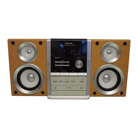
  9. Panasonic SA-PM29E User manual

Panasonic SA-PM29E User manual

This manual suits for next models

2

Other Panasonic Stereo System manuals

Panasonic SA-AK640PL User manual

Panasonic

Panasonic SA-AK640PL User manual

Panasonic SCPM11 - CD STEREO SYSTEM User manual

Panasonic

Panasonic SCPM11 - CD STEREO SYSTEM User manual

Panasonic SCPM29 - MINI HES W/CD PLAYER User manual

Panasonic

Panasonic SCPM29 - MINI HES W/CD PLAYER User manual

Panasonic RXDS5 - RADIO CASSETTE W/CD User manual

Panasonic

Panasonic RXDS5 - RADIO CASSETTE W/CD User manual

Panasonic SCPM88 - CD STEREO SYSTEM User manual

Panasonic

Panasonic SCPM88 - CD STEREO SYSTEM User manual

Panasonic SA-PMX3GN User manual

Panasonic

Panasonic SA-PMX3GN User manual

Panasonic SCPM15 - CD STEREO SYSTEM User manual

Panasonic

Panasonic SCPM15 - CD STEREO SYSTEM User manual

Panasonic RQTV0080-1P User manual

Panasonic

Panasonic RQTV0080-1P User manual

Panasonic SCPM321 - MINI HES W/CD PLAYER User manual

Panasonic

Panasonic SCPM321 - MINI HES W/CD PLAYER User manual

Panasonic SC-PM46 User manual

Panasonic

Panasonic SC-PM46 User manual

Panasonic SA-AK180PN User manual

Panasonic

Panasonic SA-AK180PN User manual

Panasonic SC-VK470 - 5 DISC CHANGER MINI COMPONENT SYSTEM. MULTI FORMAT... User manual

Panasonic

Panasonic SC-VK470 - 5 DISC CHANGER MINI COMPONENT SYSTEM. MULTI FORMAT... User manual

Panasonic SC-VK680 User manual

Panasonic

Panasonic SC-VK680 User manual

Panasonic SC-HT290 User manual

Panasonic

Panasonic SC-HT290 User manual

Panasonic SC-PMX70B User manual

Panasonic

Panasonic SC-PMX70B User manual

Panasonic SC-CH60 User manual

Panasonic

Panasonic SC-CH60 User manual

Panasonic SCAK450 - CD STEREO SYSTEM User manual

Panasonic

Panasonic SCAK450 - CD STEREO SYSTEM User manual

Panasonic RX-ES27 User manual

Panasonic

Panasonic RX-ES27 User manual

Panasonic SC-PMX7 User manual

Panasonic

Panasonic SC-PMX7 User manual

Panasonic SC-DK20 User manual

Panasonic

Panasonic SC-DK20 User manual

Panasonic SC-PM270 User manual

Panasonic

Panasonic SC-PM270 User manual

Panasonic SC-PM07 User manual

Panasonic

Panasonic SC-PM07 User manual

Panasonic SC-HC15 User manual

Panasonic

Panasonic SC-HC15 User manual

Panasonic CRS1 User manual

Panasonic

Panasonic CRS1 User manual

Popular Stereo System manuals by other brands

Sony HCD-VX88 Service manual

Sony

Sony HCD-VX88 Service manual

Philips MCM398D/12 user manual

Philips

Philips MCM398D/12 user manual

Sony CMT-SPZ90DB operating instructions

Sony

Sony CMT-SPZ90DB operating instructions

LG OM4560 owner's manual

LG

LG OM4560 owner's manual

JVC UX-G3 instructions

JVC

JVC UX-G3 instructions

Odys ODYS - LOOP instruction manual

Odys

Odys ODYS - LOOP instruction manual

Aiwa NSX-AJ700 Service manual

Aiwa

Aiwa NSX-AJ700 Service manual

Sharp CD-G10000V Operation manual

Sharp

Sharp CD-G10000V Operation manual

Bogen NEARSCAPES 4.1 manual

Bogen

Bogen NEARSCAPES 4.1 manual

Meyer LD-3 operating instructions

Meyer

Meyer LD-3 operating instructions

THOMSON MIC302U manual

THOMSON

THOMSON MIC302U manual

Philips MCM530 Service manual

Philips

Philips MCM530 Service manual

Sony SS-CEP50 Service manual

Sony

Sony SS-CEP50 Service manual

Cetacea Sound CVS-II user guide

Cetacea Sound

Cetacea Sound CVS-II user guide

Sony MHC-V21D Service manual

Sony

Sony MHC-V21D Service manual

Denon UCD-250 Service manual

Denon

Denon UCD-250 Service manual

Exibel BDX600-UK user manual

Exibel

Exibel BDX600-UK user manual

Sanyo DC-F320 Service manual

Sanyo

Sanyo DC-F320 Service manual

manuals.online logo
manuals.online logoBrands
  • About & Mission
  • Contact us
  • Privacy Policy
  • Terms and Conditions

Copyright 2025 Manuals.Online. All Rights Reserved.

nAmplifier Section
RMS Power output
10%, Total harmonic distortion
1 kHz, both channels driven
(Low channel) 35 W per channel (6 Ω)
8 kHz, both channels driven
(High channel) 35 W per channel (6 Ω)
Total Bi-Amp power 70 W per channel
Output Impedance
Headphone 16 - 32 Ω
nFM Tuner Section
Frequency range 87.5 - 108.0 MHz
Sensitivity 1.5 µV (IHF)
S/N 26 dB 1.5 µV
A
ntenna terminal(s) 75 Ω(unbalanced)
nAM Tuner Section
Frequency range
522 - 1629 kHz (9 kHz steps)
520 - 1630 kHz (10 kHz steps)
Sensitivity
S/N 20 dB (at 999 Hz) 560 µV/m
nCassette Deck Section
Track system 4 track, 2 channel
Heads
Record/playback Solid permalloy head
Erasure Double gap ferrite head
©2004 Panasonic AVC Networks Singapore Pte.
Ltd. All rights reserved. Unauthorized copying and
distribution is a violation of law.
SA-PM29E
SA-PM29EB
SA-PM29EG
Colour
(S)... Silver Type
Motor DC servo motor
Recording system AC bias 100 kHz
Erasing system AC erase 100 kHz
Tape speed 4.8 cm/s
Overall frequency response (+3 dB, -6 dB) at DECK OUT)
NORMAL (TYPE I) 35 Hz - 14 kHz
S/N 45 dB (A weighted)
Wow and flutter 0.16% (WRMS)
Fast forward and rewind time Approx. 120 seconds with C-60
cassette tape
nCD Section
Disc played
CD-DA/MP3/WMA, HighMat 8cm / 12cm, CD / CD-R / CD-RW
Sampling frequency
CD-DA 44.1 kHz
MP3/WMA 32 kHz, 44.1 kHz, 48 kHz
Bit rate
MP3 32 - 320 kbps
Decoding 16 bit linear
Pickup
Beam source / wavelength Semiconductor laser / 780nm
Number of channels Stereo
Frequency response 20Hz - 20 kHz (+1, -2 dB)
Wow and flutter Below measurable limit
Digital filter 8fs
CD Stereo System
Specification
ORDER NO. MD0403095C2
D/A converter MASH (1 bit DAC)
nGeneral
Power supply
For continental Europe AC 230 V, 50 Hz
For United Kingdom, Australia and
N.Z. AC 230-240 V, 50 Hz
Power consumption 130 W
Dimensions (W x H x D) 179 x 250 x 383 mm
Mass 5.6 kg
Power consumption in standby
mode Approx 0.9 W
1 Caution for AC Mains Lead 4
2 Before Repair and Adjustment 5
3 Protection Circuitry 5
4 Handling the Lead-free Solder 6
4.1. About lead free solder (PbF) 6
5 Precaution of Laser Diode 7
6 Handling Precautions For Traverse Deck 9
7 Accessories 10
8 Operation Procedures 11
9 Information on MP3 & WMA 12
10 About HighMAT 14
10.1. What is HighMAT? 14
10.2. Why use HighMAT? 14
10.3. The advantages of using HighMAT 14
10.4. Outline of the HighMAT standard 15
11 Assembling and Disassembling 18
11.1. Disassembly flow chart 18
11.2. Disassembly of Side Panel L & R 19
11.3. Disassembly of Top Cabinet 19
11.4. Disassembly of Deck Mechanism P.C.B and Tape Eject
P.C.B 19
11.5. Disassembly of Front Panel 20
11.6. Disassembly of Panel P.C.B, Headphone P.C.B, Switch
P.C.B and Tact switch P.C.B 20
11.7. Disassembly of Rear Panel 21
11.8. Disassembly of Main P.C.B 22
11.9. Disassembly of Transformer P.C.B 22
11.10. Disassembly of Speaker Terminal P.C.B 23
11.11. Disassembly of Power P.C.B 23
11.12. Replacement of the Power Amplifier IC 24
11.13. Procedure for Replacing Cassette Holder 24
11.14. Procedure for Replacing Pinch Roller and Head Block
(Cassette Mechanism Unit) 25
Notes :
1. Specifications are subject to change without notices. Mass and
dimensions are approximate.
2. Total harmonic distortion is measured by the digital spectrum
analyzer.
3.The labels “HIGH (HF)” and “Low (LF)” on the rear of the speakers
refer to High frequency and Low frequency.
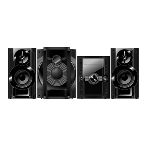
nSystem : SC-PM29E-S Music center: SA-PM9E-S
Speaker: SB-PM29P-K
nSystem : SC-PM29EB-S Music center: SA-PM29EB-S
Speaker: SB-PM29P-K
nSystem : SC-PM29EG-S Music center: SA-PM29EG-S
Speaker: SB-PM29EG-K
11.15. Procedure for Replacing Motor, Capstan Belt A, Capstan
Belt B, and Winding Belt (Cassette Mechanism Unit) 26
11.16. Procedure for Replacing Parts on Mechanism PCB 27
11.17. Disassembly of CR16 Mechanism 28
11.18. Replacement of optical pickup unit (CD mechanism) 29
11.19. Replacement of a traverse gear A and a traverse gear B
31
11.20. Procedure for removing CD loading mechanism 32
11.21. CR16 mechanism disassembly procedure 32
11.22. CR16 MECHANISM ASSEMBLY PROCEDURE 38
11.23. Disassembly of traverse mechanism 51
11.24. Handling of cassette tape jam 52
12 Service Positions 53
12.1. Checking procedure 53
12.2. Checking the major P.C.B 53
13 Self-Diagnostic Display Function 54
13.1. Preparations 54
13.2. Setting of the Self-Diagnostic Mode 54
13.3. Restoring Normal Display 54
13.4. Clearing Self-Diagnostic Memory 54
13.5. Displaying Self-Diagnostic Results 54
14 Procedure for Checking Operation of Individual Parts for
Cassette Mechanism Unit 57
14.1. Operation Check with Cassette Tape 57
14.2. Operation Check without Cassette Tape 57
15 Measurement And Adjustments 59
15.1. Cassette Deck Section 59
16 Block Diagram 61
16.1. CD Servo Block 61
16.2. Main Block 63
17 Notes of Schematic Diagram 69
18 Schematic Diagram 70
18.1. CD Servo Circuit 70
CONTENTS
Page Page
2
SA-PM29E / SA-PM29EB / SA-PM29EG
18.2. Main Circuit 72
18.3. Panel Circuit, Tact Switch Circuit, Headphone Circuit and
Switch Circuit 76
18.4. Deck Circuit, Deck Mechanism Circuit and Tape Eject
Circuit 79
18.5. Power Circuit 81
18.6. Transformer Circuit and Speaker Terminal Circuit 84
18.7. CD Loading Circuit 85
19 Printed Circuit Board 86
19.1. CD Servo P.C.B. (Side A and Side B) 86
19.2. Main P.C.B. 88
19.3. Panel P.C.B. and Tact Switch P.C.B. 90
19.4. Switch P.C.B., Headphone P.C.B. and Speaker Terminal
P.C.B. 91
19.5. Deck P.C.B. and Tape Eject P.C.B. 92
19.6. Deck Mechanism P.C.B and CD Loadind P.C.B. 93
19.7. Power P.C.B. 94
19.8. Transformer P.C.B. 95
20 Wiring Connection Diagram 96
21 Illustration of IC 痴, Transistors and Diodes 98
22 Terminal Function of ICエs 99
22.1. IC701 (AN22004A-NF) IC HEAD AMP 99
22.2. IC702 (MN6627931BL) IC LSI 99
22.3. IC703 (BA5948FPE2) IC 4CH DRIVE 100
22.4. IC302 (C2CBJG000409) MICRO PROCESSOR 100
23 Troubleshooting Flowchart (CD Section Circuit) 102
24 Parts Location and Replacement Parts List 104
24.1. Deck Mechanism 105
24.2. CD Loading Mechanism 107
24.3. Cabinet Part List 112
24.4. Electrical Part List 116
24.5. Packaging Materials & Accessories Parts List 124
24.6. Packaging 124
3
SA-PM29E / SA-PM29EB / SA-PM29EG
2 Before Repair and Adjustment
Disconnect AC power, discharge Power Supply Capacitors C506, C507, C508, C584, C587, C588 & C311 through a 10Ω,5W
resistor to ground.
DO NOT SHORT-CIRCUIT DIRECTLY (with a screwdriver blade, for instance), as this may destroy solid state devices.
After repairs are completed, restore power gradually using a variac, to avoid overcurrent.
·
For E, EG Current consumption at AC 230V, 50 Hz in NO SIGNAL mode should be ~300 mA.
·
For EB Current consumption at AC 230V - 240V, 50 Hz in NO SIGNAL mode should be ~300 mA.
3 Protection Circuitry
The protection circuitry may have operated if either of the following conditions are noticed:
·
No sound is heard when the power is turned on.
·
Sound stops during a performance.
The function of this circuitry is to prevent circuitry damage if, for example, the positive and negative speaker connection wires are
"shorted", or if speaker systems with an impedance less than the indicated rated impedance of the amplifier areused.
If this occurs, follow the procedure outlines below:
1.Turn off the power.
2.Determine the cause of the problem and correct it.
3.Turn on the power once again after one minute.
Note:
When the protection circuitry functions, the unit will not operate unless the power is first turned off and then on again.
5
SA-PM29E / SA-PM29EB / SA-PM29EG
12 Service Positions
12.1. Checking procedure
Note : For the disassembling procedure, see the section 11.
12.2. Checking the major P.C.B
1. Disassembly of Side Panel L & R
2. Disassembly of Top Cabinet
3. Disassembly of Deck Mechanism P.C.B and Tape Eject P.C.B
4. Disassembly of Front Panel
5. Disassembly of Panel P.C.B Headphone P.C.B, Switch P.C.B and Tact switch P.C.B
6. Disassembly of Rear Panel
7. Disassembly of Main P.C.B
8. Disassembly of Transformer P.C.B
9. Disassembly of Speaker Terminal P.C.B
10. Disassembly of Power P.C.B
11. Disassembly of CR16 Mechanism.
53
SA-PM29E / SA-PM29EB / SA-PM29EG
13 Self-Diagnostic Display Function
This unit is equipped with a self-diagnostic display function, which will be useful during servicing and maintenance.
·
Refer to the next page for display symbols, symptoms, etc.
13.1. Preparations
1.A Cr02-positioned blank cassette tape with an erase prevention niche on either Side A or B.
2.A normal-positioned music tape with erase prevention niches on both Sides A and B. Both tapes are halfway forwarded in
advance.
3.The remote controller that comes with this unit.
13.2. Setting of the Self-Diagnostic Mode
No. Operation Procedure Operation and Processing of Microcomputer
1Switch the SELECTOR to CD. There should be NO disc
loaded.
2Press the [STOPn] key for 2 sec and press [CD PLAY] for
another 2 sec, it shall enter into the diagnostic mode. [T ] shall be displayed in the FL.
13.3. Restoring Normal Display
·
From the F76 display, the normal display does not appear till an error is recovered.
·
For displays other than F76, press “POWER” button to turn off the power, and then turn on the power.
13.4. Clearing Self-Diagnostic Memory
<CD Section> (F15, F17, F22, F26, F27, F28, F29)
1. Enter a self-diagnostic mode.
2.Press "STOPn/-DEMO" button. A symbol of self-diagnostic is indicated on the display if an error is found. If several errors are
found, a respective indication is displayed when "STOPn/-DEMO" button is pressingrepeatedly. (e.g. H01 →CD F15 →F01)
If no error is found, only "T " indication is displayed and remains unchange even if "STOPn/-DEMO" button is pressed.
13.5. Displaying Self-Diagnostic Results
<Cassette Deck Section> (H01, H02, H03, F01, F02)
1.Enter the self-diagnostic mode, following the instructions described in [13.2. Setting of the Self-Diagnostic Mode].
2.Insert a normal-positioned music tape with erase prevention niches on both Sides A and B. Press [TAPE ] button to activate
the TPS operation so that the tape automatically stopsat an interval between music selections.
3.Press [STOPn/-DEMO] and [TAPE ] buttons together on the remote controller. (Recording does not start.)
4.Then, insert a Cr02-positioned blank cassette tape with an erase prevention niche of Side A or B set to the left side.
5.Press [ /FF/ ] button on the remote control. The tape will be forwarded and automatically stopafter two seconds.
6.Remove the cassette tape, and set the other side.
7.Press [ /REW/ ] button on the remote control. The tape will be rewound and automatically stopsafter two seconds.
8.Press [STOPn/-DEMO] button on the unit.
If an error is found, a self-diagnostic key appears on the display.
If several errors are found, the display shows these keys when [STOPn/-DEMO] button is pressed repeatedly. (Ex.: H01 - H02
- F01 - H01)
If no error is found, only the message, “CD TEST” appears on the display.
54
SA-PM29E / SA-PM29EB / SA-PM29EG
(*1) TPS operation (music search) detects the blank sections between music selections. Therefore, do not use tapes with the
following conditions:
·
A blank section that lasts only 4 seconds or less.
·
No blank sections (recording through microphones, etc.).
·
Music selections that have extremely low pitches or prolonged silent sections (such as classical music).
·
and/or Music recorded with fade in/out effect.
13.5.1. Error detection for CD Block
Error Code Abnormal Items Possible Cause
F15 CD REST SW abnormal CD traverse position intial setting operation failsafe counter (1000 ms) waiting for REST SW to
turn on. Error No. shall be clear by force or during coldstart.
H15 The CD tray closes CD disc tray detect switch NG. (Check and replace)
F26 CD servo LSI command
signal abnormal CD function DTMS command, after system setting, If SENSE = ‘L’ cannot be detected.
Memory shall contain F26 code. After Power on, CD function shall continue, error shall occur
“NODISC”.
Error No. shall be clear by force or coldstart.
F28 DISC LOAD abnormal While going to play position, if failsafe counter is finished and switch o change or switch
target condition was not achieve, this error shall be memorized. Next time mechanism
operates, it shall do coldstart.
ErrorNo. shall be clear by force or coldstart.
F29 DISC unload abnormal While going to play position, if failsafe counter is finished and switch no change or switch
target condition was not achieve, this error shall be memorized. Next time mechanism
operates, it shall do coldstart.
ErrorNo. shall be clear by force or coldstart.
F27 Slide operation abnormal During vertical operation, if failsafe timer is finished and switch no change or switch target
condition was not achieve, this error shall be memorized. Next time mechanism operates, it
shall do coldstart.ErrorNo. shall be clear by force or coldstart.
F17 Down SW abnormal During vertical operation going to the bottom position, if failsafe timer is finished and switch
no change or switch target condition was not achieve, this error shall be memorized. The
Next time mechanism operates,it shall do mechanism initialization.Error No. shall be clear by
force or coldstart.
F22 Loading Mode / Mecha
abnormal During mecha initialization, Loading mode mechanism abnormal, normal operation cannot be
achieve. The next time mechanism operates, it shall do mechanism initialization.Error No.
shall be clear by force or coldstart.
Abnormal item Error Display Method of detection
F75 CD power abnormal Under normal operation (self-diagnostic mode inclusive), check if CDRST is H for SELECTOR
at CD. If it is not H after 1 sec, it shall be memorised as an error.
13.5.2. Error detection code for Cassette Mechanism Block
Error Code Abnormal Items Possible Cause
H01 MODE SW abnormal Normal operation during mecha transition, MODE SW abnormal is memorised. The content
of abnormality can be confirmed in the abnormal detection mode explained in the later
section.
H02 REC INH SW abnormal The content of abnormality can be confirmed in the abnormal detection mode explained in
the later section.
H03 HALF SW abnormal
F01 Reel pulse abnormal
F02 TPS abnormal
13.5.3. Doctor Mode set up
a) At any more (CD, TAPE, TUNER).
b) To enter Doctor Mode, press Doctor Mode key [C2DF] of special remote control or input 4 then 7 from the remote control while
pressing STOP nkey of the main set.
13.5.4. Cold start setting
55
SA-PM29E / SA-PM29EB / SA-PM29EG
(Note) In the case that you unplug from AC outlet after this mode was set, then plug to AC again, a cold start shall begin.
And “- - - - - - - - -” is displayed in the FL for 2 seconds.
56
SA-PM29E / SA-PM29EB / SA-PM29EG
14 Procedure for Checking Operation of Individual Parts for
Cassette Mechanism Unit
14.1. Operation Check with Cassette Tape
1.Pull up the EJECT lever using a rubber band. (Cf. Fig. 6)
2.Supply DC5V to MOTOR. (→MOTOR rotates.) (Cf. Fig. 5)
3.Insert a cassette tape to the unit.
4.Supply DC9V to the plunger, and turn the power ON and OFF. (→Power +PL, -PL) (Cf. Fig. 5)
a.FWD PLAY: Supply the plunger power in a flash. (ON: approx. 5msec)
b.FWD FF: Supply the plunger power in a flash at PLAY mode. (ON: approx. 5msec)
c.STOP: Supply the plunger power in a flash at FWD FF mode. (ON: approx. 5msec)
d.REV PLAY: Supply the plunger power in a normal timing at STOP mode. (ON: approx. 200msec)
e.REV REW: Supply the plunger power in a flash at REV PLAY mode. (ON: approx. 50msec)
f.STOP: Supply the plunger power in a flash at FF mode. (ON: approx. 50msec)
Repeat the operation (→FWD PLAY)
(Note) Other operation may start if a timing of supplying the plunger power is missed.
14.1.1. Connection Status between Mechanism and Power Supply (Motor, Plunger)
14.1.2. Operative Parts of Mechanism Unit (EJECT lever fitted with rubber band,
Plunger/Rib operation)
14.2. Operation Check without Cassette Tape
1.Pull up the EJECT lever using a rubber band. (Cf. Fig. 6)
2.Supply DC5V to MOTOR. (→MOTOR rotates.)
3.Lift up the mechanism unit’s plunger/rib with the tip of a negative screwdriver, and operate the unit in the same timing as
supplying the power. (Cf. Fig. 7)
57
SA-PM29E / SA-PM29EB / SA-PM29EG
58
SA-PM29E / SA-PM29EB / SA-PM29EG