2
TABLE OF CONTENTS
PAGE
1 Safety Precautions -----------------------------------------------3
1.1. General Guidelines ----------------------------------------3
1.2. Touch-Current Check--------------------------------------3
2Warning--------------------------------------------------------------4
2.1. Prevention of Electrostatic Discharge (ESD)
to Electrostatically Sensitive (ES) Devices ----------4
2.2. About lead free solder (PbF) ----------------------------5
3 Service Navigation------------------------------------------------6
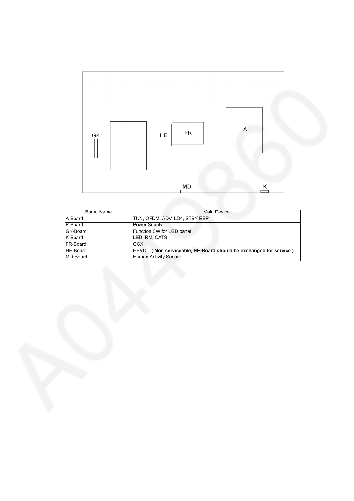
3.1. PCB Layout --------------------------------------------------6
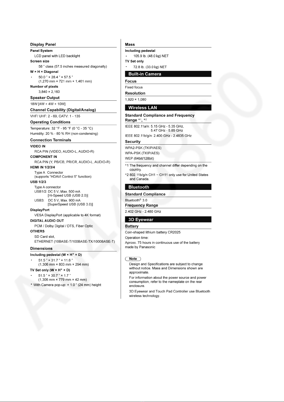
4 Specifications ------------------------------------------------------7
5 Technical Descriptions------------------------------------------8
5.1. Specification of KEY for DTCP-IP, WMDRM
and Widevine------------------------------------------------8
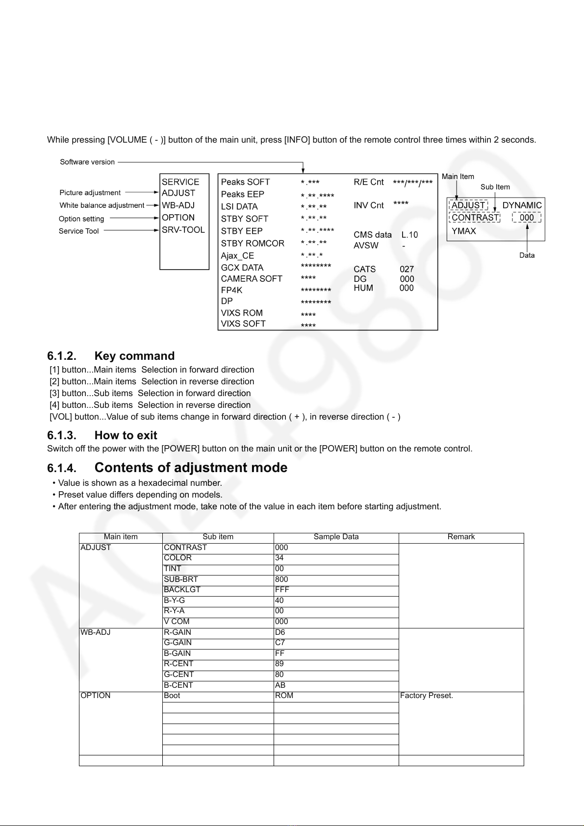
6 Service Mode -------------------------------------------------------9
6.1. How to enter into Service Mode ------------------------9
6.2. SRV-TOOL------------------------------------------------- 10
6.3. Hotel mode------------------------------------------------- 11
6.4. Data Copy by USB Memory --------------------------- 12
7 Troubleshooting Guide---------------------------------------- 15
7.1. Check of the IIC bus lines------------------------------ 15
7.2. Power LED Blinking timing chart --------------------- 16
7.3. LCD Panel test mode / FR test mode--------------- 16
8 Disassembly and Assembly Instructions --------------- 17
8.1. Disassembly Flow Chart for the Unit ---------------- 17
8.2. Disassembly Procedure for the Unit----------------- 17
9 Measurements and Adjustments -------------------------- 36
9.1. Voltage chart of A-Board ------------------------------ 36
9.2. Voltage chart of P-Board ------------------------------- 36
9.3. Voltage chart of HE-Board ----------------------------- 36
9.4. Voltage chart of FR-Board ----------------------------- 36
10 Block Diagram --------------------------------------------------- 37
10.1. Main Block Diagram ------------------------------------- 37
10.2. Block (1/3) Diagram ------------------------------------- 38
10.3. Block (2/3) Diagram ------------------------------------- 39
10.4. Block (3/3) Diagram ------------------------------------- 40
11 Wiring Connection Diagram --------------------------------- 41
11.1. Caution statement.--------------------------------------- 41
11.2. Wiring (1) --------------------------------------------------- 41
11.3. Wiring (2) --------------------------------------------------- 42
11.4. Wiring (3) --------------------------------------------------- 43
11.5. Wiring (4) --------------------------------------------------- 44
11.6. Wiring (5) --------------------------------------------------- 44
12 Schematic Diagram--------------------------------------------- 45
13 Printed Circuit Board ------------------------------------------ 45
14 Exploded View and Replacement Parts List ----------- 45
14.1. Exploded View -------------------------------------------- 45
14.2. Electrical Replacement Parts List-------------------- 45