manuals.online logo
Brands
  1. Home
  2. •
  3. Brands
  4. •
  5. Panasonic
  6. •
  7. VCR System
  8. •
  9. Panasonic NV-FJ617EE User manual

Panasonic NV-FJ617EE User manual

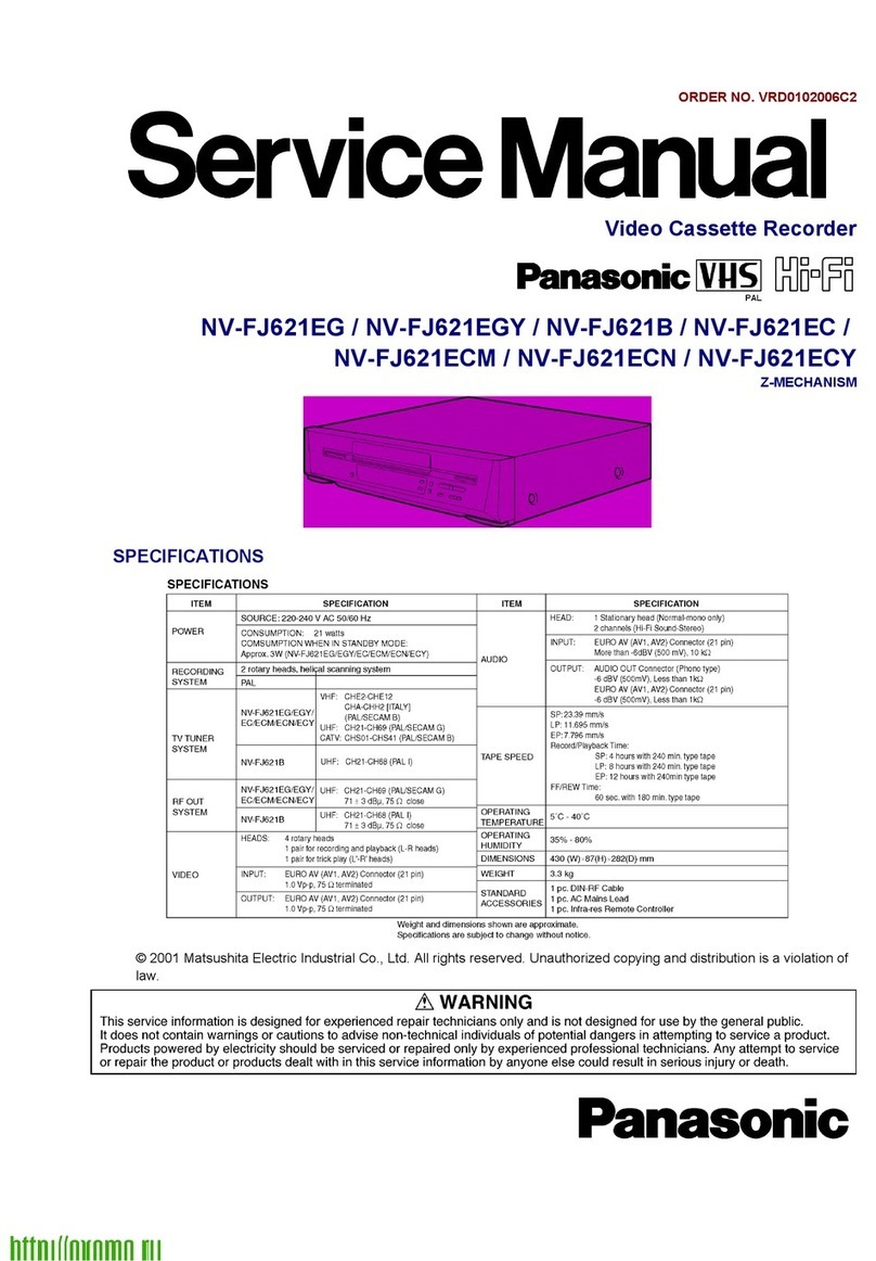
ORDERNO. VRD0005018C2
Video Cassette Recorder
NV-FJ617EE / NV-FJ712EE / NV-FJ762EE
Z-MECHANISM
SPECIFICATIONS
1
2000 Matsushita ElectricIndustrial Co., Ltd. All rights reserved.
Unauthorized copying and distribution isaviolation of law.
1. INTRODUCTION
This service manual contains technical information whichwill allowservice personnel to
understand and service this model.
If the circuit is changedormodified, this information will be followedbysupplementaryservice
manual tobe filedwithoriginal service manual.
Note:
1. Adjustment procedures, DisassemblyProcedures and Assembly
Procedures for Mechanism Chassisare separate volume from this
service manual. / Please refer to the service manual for Z-
Mechanism Chassis. (Order No. VRD9802005C2)
2. The Model No. isindicated on the SchematicDiagram and Circuit
Board Diagrams as follows.
Model No. Indication Mark
NV-FJ617EE (617)
NV-FJ712EE (712)
NV-FJ762EE (762)
2. GENERAL DESCRIPTIONS
2.1. SERVICECAUTION-1 / (NV-FJ712EE, FJ762EE ONLY)
REPLACING IC7701, IC7703 and/orB7701
Whenthe OSD-MicroprocessorIC7701, S-RAM IC7703 and/orBack-up batteryB7701 are
replaced, the Tape Librarydata will not be available.Therefore, back up the Tape Librarydata
first, thenperform necessaryservicing.
NOTE:
*The Tape Librarysystemis achievedusing not onlythe data of whichis recordedon the tape
but alsothe data is storedinS-RAM IC7703.
*The storeddata inS-RAM IC7703 is backedup byusing the powersource of: / *AC Connected:
2
AC Powersouse / *AC Disconnected:Back-up Battery(B7701).
NOTE:
Evenif the OSD PACK CBA(VEP07A12A/B/D/E) is disconnectedfromthe VCR, the poweris still
suppliedfromBack-up battery.
2.1.1. REPLACING PROCEDURE
2.1.1.1. PREPARATION
NOTE:
It is necessarythat the Tape LibrarySystemhas tooperate properly.
STEP1.BACK UP THE TAPE LIBRARY DATA
1. Connect aTV and aRFAerial lead to the VCR and receive one of
TV station.
2. Record the TV programme for at least 15 minuets inthe SP mode
(25 minuets inthe EP mode) on aCassette Tape.
2.1.1.2. REPLACEMENT
STEP2.REPLACE THE IC7701, IC7703 AND/OR B7701
1. Remove the C.B.A. with Mechanism unitbyreferring the
Disassemblyprocedure.
2. Disconnect the AC plug and replace the IC7701, IC7703 and/or
B7701.
STEP3.RESTORE THE TAPE LIBRARY DATA
1. Using the Remote controller:
A. Press the MENU button and then the Cursor buttons to select
"Tape Library".
B. Select "Restore data" and Press the OKbutton.
2. Insert the Backed-up cassette tape into the VCR. / The restoration
of Librarydata starts automatically. / (Ittakes some time to be
completed.)
3
3. Store the Tape Librarydata accordingly.
2.2. SERVICECAUTION-2
REPLACING IC7801
Whenthe EEPROM IC7801 is replaced, propermodel code, option code and electrical
adjustment data will not be available.Therefore, enterthe necessarydata afterreplacing IC7801.
2.2.1. REPLACING PROCEDURE
STEP1.REPLACEMENT
1. Disconnect the AC plug and replace the IC7801.
STEP2.INPUTTHE MODEL& OPTION CODE
1. Set up the model code and option code byordering the following
table.
PROCEDURES FIP Display
Turnon the Service Mode
1."Turnthe Jog dial tofullyFF"*
1and press the EJECTkey
simultaneouslyformore than3
seconds.
Activate the Service Mode 2
2."Turnthe Jog dial tofullyFF"*
1and press the EJECTkeyin
twice.
Activate the Entering Mode.
3.Press the EJECTkeyinmore
than3 seconds.
Set the Mode 2.
4.Press the CH UP keyintwice.
Displaythe Setting Code.
5.Press the POWER Button.
(POWER ON)
(Colon starts
flashing)
4
PROCEDURES FIP Display
Enterthe Model and Option Code .
6.Set the Model and Option code byusing REW,
PLAY, STOP and FF keys on the Remote
Controller. (See Fig.S1 & S2)
Exit fromService Mode.
7.Press the POWER Button.
(POWER OFF)
8. "Turnthe Jog dial tofullyFF"
*1 and press the EJECTkey
simultaneouslyin6 times.
(Normal
Indication)
*1:NV-FJ762EE only. As forNV-FJ712EE and NV-FJ617EE, press the FF keyinsteadof "turning
the Jog dial."
Fig.S1 Service Screen(sample)
Model No. Model
/
Code
Option
/
Code
1
Option
/
Code
2
Option
/
Code
3
NV-FJ617EE 120 08 65 180
NV-FJ712EE 152 08 117 119
NV-FJ762EE 153 08 117 119
Fig. S2 Model Code & Option Code
NOTE:
Since all electrical adjustments data is still not available, perform the Electrical Adjustment
continuously.
2.3. SERVICEINFORMATION
2.3.1. CYLINDER UNITREPLACEMENT
5
1. CYLINDERUNITREPLACEMENT
A. Remove the mechanism unitfrom MAINC.B.A./Chassisby
referring “SECTION2. DisassemblyProcedure”.
B. Remove the 3screws(A)of the CYLINDERUNITwith ascrew
driver.
C. Unlock the 4locking tabs (B)and disconnect the Cylinder
flexiblecard from the FPCHolder.
D. Remove the CYLINDERUNIT.
CAUTION:
Handlethe Cylinder flexiblecard with care. When itdamaged, you
shouldreplace wholeCylinder unit.
Fig. S3
2. UPPERCYLINDERDISASSEMBLY
A. Remove 2screws(A).
B. Remove the Cylinder Stator Unit.
C. Remove 2screws(B).
D. Remove the Cylinder Rotor Unit.
E. Loose Hex screw (C)(1.5mm) and remove the CYLINDER
RETAINER.
F. Remove the Upper Cylinder. Fig. S4
6
3. UPPERCYLINDERASSEMBLY
When reassembling, perform the steps inthe reverse order.
Notes:
1. Install the Cylinder Retainer so that the 2holes on top of the
Cylinder Retainer are at right angles with the P3502 Connection.
2. Tighten the Hex screw (C)(1.5mm) whilepressing downon top of
the Cylinder Retainer. Fig. S5
7
3. Install the Cylinder Rotor Unitso that the inner holeof the
Cylinder Rotor Unitfits to the small projection (D)on top of the
Upper Cylinder.
4. Tighten 2screws(B). Fig. S6
5. install the Cylinder Stator Unit.
6. Tighten 2screws(A). Fig. S7
7. Confirm the PG SHIFTERADJUSTMENTwith the alignment tape
8
(PAL: VFJ8125H3F) and adjust itifnecessary.
2.3.2. CHECKING OFMAIN C.B.A.
Whenservicing the MAIN C.B.A., take out the MAIN C.B.A. and mechanismfromthe frame and
turnover.
And thenconnect the Extension Cable (VFK2744) betweenthe POWER C.B.A. connector(P1103)
and the MAIN C.B.A. connector(P1001) as shownin Fig. S8.
Fig. S8
2.3.3. FLATCARD CABLE INSTALLATION
Wheninstalling the Flat CardCable on the connector, install the Flat CardCable withthe cable
contacts facing the connectorcontacts.
Fig. S9
2.4. REMOVALOFCASSETTE TAPE
There are 2 ways toremove a cassette tape.
1. Service Information DisplayOperation
A. Turn on the Service Mode by:/ (NV-FJ762EE) / Rotating the Jog
dial to fullyFF side and press the EJECTkeysimultaneouslyfor
3seconds. / (NV-FJ617EE and NV-FJ712EE) / Pressing the FF
and the EJECTkeysimultaneouslyfor 3seconds. / Then select
9
the Service Mode 7byrepeating above operation in7times.
B. Press STOPkeyinorder to rotate the Loading Motor for
unloading operation. (Payan attention of tape slack)
2. Manual Operation
A. Disconnect the AC Mains Lead and remove the Top Panel.
B. Rotate the MainCam Gear clockwise until the Loading Posts
move to fullyunloaded position as shownin Fig. S10. (Tape is
remaining) Fig. S10
C. Rotate the Capstan Motor clockwise from the bottom side to
take up the tape. Fig. S11
D. Rotate the MainCam Gear clockwise until the cassette tape is
ejected.
2.5. INTRODUCTIONOFVIDEO HEAD CLEANING CASSETTE /
(POLISHING TYPE)
1. We are pleased to introduce PanasonicVideo Head Cleaning
Cassette, VFK0923FT [for service purposes] and VFK0923FSE [
for end users] for all VHS/SVHSVCPand VCR.
2. These cleaning cassettes are exclusive removing the hard and
stickyclogging on video heads.
10
3. These improve the efficiencyof video head cleaning service and
shortening cleaning time for end users.
VFK0923FT
(ForService usage)
Type of Cassette Full VHS Cassette
Cleaning Time 10 Seconds/Time
Tape Length 20 m
Usabilityina Path 180 Times
VFK0823FSE
(Forend users)
Type of Cassette Full VHS Cassette
Cleaning Time 10 Seconds/Time
Tape Length 3.34 m
Usabilityina Path 30 Times
11
VFK0823FSE
(Forend users)
Note:
The tape material itselfisthe same inboth types.
2.6. HOWTO REPLACETHELITHIUMBATTERY(NV-FJ712EE,
FJ762EE)
(PROCEDURE)
1. Remove the Top Panel. (Refer to DisassemblyProcedures)
2. Unsolder the Lithium battery“CR2354-1GUF” and then replace
the new one. (See Fig. B1)
Fig. B1
NOTE:
The lithiumbatteryis a critical component (Type No.: CR2354-1GUFManufacturedby
Panasonic.)
It must neverbe subjectedtoexcessive heat ordischarge.
It must therefore onlybe fittedinequipment designedspecificallyforits use.
12
Replacement batteries must be of the same type and manufacture.
Theymust be fittedinthe same mannerand location as the original battery, withthe correct
polaritycontacts observed.
Donot attempt tore-charge the oldbatteryorre-use it foranyotherpurpose.
It shouldbe disposedof inwaste products destinedforburial ratherthanincineration.
3. ADJUSTMENT PROCEDURES
3.1. DISASSEMBLY METHOD
3.1.1. DISASSEMBLY FLOW CHART
This flowchart indicates disassemblysteps of the cabinet parts and the circuit boards inorder
tofind the necessaryitems forservicing.
Whenreassembling, perform the steps inthe reverse order.
Fig. D1
13
3.1.2. DETAILOFDISASSEMBLY METHOD
1. REMOVALOFTHETOPPANEL
Remove 4 Screws (A)
Fig.D2
2. REMOVALOFTHEFRONTPANEL UNIT
14
Pull out JOG & SHUTTLE Ring /
(NV-FJ762EE)
Unlock 7 Tabs (B)
Fig. D3
3. REMOVALOFTHEPOWERC.B.A.
Disconnect Bridge Connector(C)
Unlock 6 Tabs (D)
Fig. D4
COUTIONS:
Please payan attention to disconnect the connector (P1001-
P1103) which connected between MainC.B.A. and Power supply
unitas shownbelow. Fig. D5
15
Asabove drawing, disconnect the connector bySCREW DRIVER
from the direction (A). / Donot disconnect from direction (B)
because itispossibilityto damage the parts located bythe
connector.
4. REMOVALOFTHEAVFRONTC.B.A. &JOG SHUTTLE C.B.A.
REMOVALOFTHE AV FRONTC.B.A.
Unlock 2 Tabs (E)
REMOVELOFTHE JOG/SHUTTLE C.B.A. / (NV-
FJ762EE)
Unlock 2 Tabs (F)
Disconnect Bridge Connector(G)
Fig. D6
5. REMOVALOFTHEMECHANISM UNIT
Remove 3 Screws (H)
Remove 2 Screws (I)
Remove Screw(J)
Note:
1. Keep pressing 2stoppers on Cassette Holder Plate and Press
Cassette Holder Plate to the rear.
16
2. Remove the Mechanism Unitafter bend the Cylinder Shieldinthe
direction of the arrow.
Fig. D7
6. REMOVALOFTHEMAINC.B.A.
Disconnect Bridge Connector(C)
Remove Screw(K)
Unlock 7 Tabs (L)
Fig. D8
17
7. SERVICING POSITION Fig. D9
3.2. MECHANICALADJUSTMENTPROCEDURES
Refertothe Service Manual forZ-MechanismChassis. / (OrderNo. VRD9802005C2)
3.3. ELECTRICALADJUSTMENTPROCEDURES
3.3.1. TESTEQUIPMENT
The following equipments are requiredforElectrical Adjustments.
1. Dual-Trace Oscilloscope
-Voltage Range: 0.005-5V/div
-FrequencyRange: DC-35MHz
-Probes: 10:1 / 1:1
2. FrequencyCounter
-FrequencyRange: 0-10MHz
-Probes: 1:1
3. Universal Counter
4. Digital VoltMeter (D.V.M.)
5. Video Sweep Generator
6. Sinewave Generator
7. Video Pattern Generator
8. Monitor TV
9. DC Power Supply
10. VHSBlank Tape
11. VHSAlignment Tape
18
-Parts No.:VFJ8125H3F(PAL)
3.3.2. VCR SETTING
Whenno indication inthe procedure, set eachselectoras follows.
1. TAPE SPEED:SP
2. CHANNEL: AV1/AV2/AV3
(Set to signal input terminal number)
3.3.3. ADJUSTMENTS
ITEM TP ADJ. MODE INPUT TAPE M. EQ.
PG SHIFTER /
ADJUSTMENT --- --- PLABACK --- ALIGNMENT
TAPE / (PAL) ---
AI FUNCTION /
ADJUSTMENT --- --- PLAYBACK /
(SELF-REC) PAL/
COLOUR /
BAR
BLANK / TAPE ---
VIDEO /
FREQUENCY /
RESPONSE /
ADJUSTMENT
VIDEO
OUT --- SP/LP /
PLAYBACK /
(SELF-REC)
VIDEO /
SWEEP /
(See Fig.
E1)
BLANK TAPE OSCILLO /
SCOPE/ /
VIDEO
SWEEP
GENERATOR
VXO / FREE-RUN
FREQUENCY
ADJUSTMENT
(NV-FJ712EE,
FJ762EE)
TL7711 VC7701 STOP ... NO FREQ.
COUNTER
19
Fig. E1
CONDITION: BURSTSIGNAL
OFF / 75 ohmTERMINATED
Fig. E2
3.3.4. PG SHIFTER ADJUSTMENT/ (AUTOMATIC)
Fig. E3
PROCEDURES FIP Display
"Turnthe Jog dial tofullyFF"*1
and press the EJECTkey
simultaneouslyfor3 seconds.
"Turnthe Jog dial tofullyFF"*1
and press the EJECTkey
simultaneouslytwice.
Press the EJECTkeyfor3
seconds.
Press the CH UP keyonce.
Insert the Alignment Tape.
(PAL: VFJ81215H3F)
This adjustment is
automaticallystarted. / (During
the adjustment, the picture will
be appearedon the monitor.)
Whenthis Adjustment is terminated, the following
operation will be activated.
-Adjustmentcompleted:Thetapewill beejected.
-Adjustmentincompleted:"F2*" isindicated on theFIP.Check theServo/
System Control circuitand Cylinder Unit.
To release Service Mode, "Turnthe Jog dial to
fullyFF"*1 and press the EJECTkey
simultaneously6 times until the normal indication
on the FIP.
NOTE:
20

This manual suits for next models

2

Other Panasonic VCR System manuals

Panasonic NV-FJ720 Series User manual

Panasonic

Panasonic NV-FJ720 Series User manual

Panasonic Omnivision VHS PV-4415S User manual

Panasonic

Panasonic Omnivision VHS PV-4415S User manual

Panasonic PV-V4022-A User manual

Panasonic

Panasonic PV-V4022-A User manual

Panasonic NV-FJ610PMP User manual

Panasonic

Panasonic NV-FJ610PMP User manual

Panasonic NV-SD420 Series User manual

Panasonic

Panasonic NV-SD420 Series User manual

Panasonic NV-SJ4130PN User manual

Panasonic

Panasonic NV-SJ4130PN User manual

Panasonic NV-G15EM User manual

Panasonic

Panasonic NV-G15EM User manual

Panasonic Omnivision VHS PV-4465S User manual

Panasonic

Panasonic Omnivision VHS PV-4465S User manual

Panasonic NV-P01M2AM User manual

Panasonic

Panasonic NV-P01M2AM User manual

Panasonic NV-HD70EA User manual

Panasonic

Panasonic NV-HD70EA User manual

Panasonic NV-SJ400A User manual

Panasonic

Panasonic NV-SJ400A User manual

Panasonic NV-L20A User manual

Panasonic

Panasonic NV-L20A User manual

Panasonic NV-HS1000EC User manual

Panasonic

Panasonic NV-HS1000EC User manual

Panasonic PV-V453-K User manual

Panasonic

Panasonic PV-V453-K User manual

Panasonic AJ-D455 User manual

Panasonic

Panasonic AJ-D455 User manual

Panasonic Omnivision PV-V4540 User manual

Panasonic

Panasonic Omnivision PV-V4540 User manual

Panasonic NV-MV21EB User manual

Panasonic

Panasonic NV-MV21EB User manual

Panasonic NV-HD90 User manual

Panasonic

Panasonic NV-HD90 User manual

Panasonic NV-HD630 series User manual

Panasonic

Panasonic NV-HD630 series User manual

Panasonic NV-F55EA User manual

Panasonic

Panasonic NV-F55EA User manual

Panasonic Omnivision PV-V4601 User manual

Panasonic

Panasonic Omnivision PV-V4601 User manual

Panasonic Omnivision PV-V4523S User manual

Panasonic

Panasonic Omnivision PV-V4523S User manual

Panasonic NV-FJ600 Series User manual

Panasonic

Panasonic NV-FJ600 Series User manual

Panasonic Omnivision PV-4655S User manual
Panasonic

Panasonic Omnivision PV-4655S User manual

Popular VCR System manuals by other brands

Sony SLV-777HF - Video Cassette Recorder Service manual

Sony

Sony SLV-777HF - Video Cassette Recorder Service manual

Sony SL-C6E Service manual

Sony

Sony SL-C6E Service manual

Philips VR 948 operating manual

Philips

Philips VR 948 operating manual

JVC HR-DVS2EU instructions

JVC

JVC HR-DVS2EU instructions

THOMSON M9950 user manual

THOMSON

THOMSON M9950 user manual

Toshiba MV9DL2 Service manual

Toshiba

Toshiba MV9DL2 Service manual

Zenith VRB210 operating guide

Zenith

Zenith VRB210 operating guide

Sharp VC-FH70GM Operation manual

Sharp

Sharp VC-FH70GM Operation manual

RCA VR538 user guide

RCA

RCA VR538 user guide

American Dynamics ADV096HD datasheet

American Dynamics

American Dynamics ADV096HD datasheet

JVC HR-S9911U - S-VHS Hi-Fi Stereo VCR instructions

JVC

JVC HR-S9911U - S-VHS Hi-Fi Stereo VCR instructions

Emerson EWV601A owner's manual

Emerson

Emerson EWV601A owner's manual

Philips VR340/55 Service manual

Philips

Philips VR340/55 Service manual

Symphonic 5900 owner's manual

Symphonic

Symphonic 5900 owner's manual

Philips VR 475 operating instructions

Philips

Philips VR 475 operating instructions

RCA VR355/VR545 user guide

RCA

RCA VR355/VR545 user guide

Sanyo VHR-M262EV Service manual

Sanyo

Sanyo VHR-M262EV Service manual

Grundig GV 7400 EURO Service manual

Grundig

Grundig GV 7400 EURO Service manual

manuals.online logo
manuals.online logoBrands
  • About & Mission
  • Contact us
  • Privacy Policy
  • Terms and Conditions

Copyright 2025 Manuals.Online. All Rights Reserved.