manuals.online logo
Brands
  1. Home
  2. •
  3. Brands
  4. •
  5. Panasonic
  6. •
  7. VCR System
  8. •
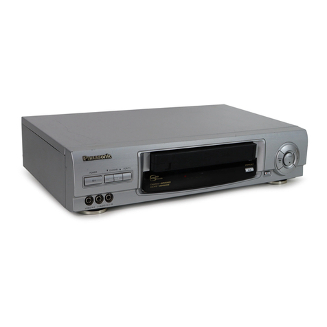
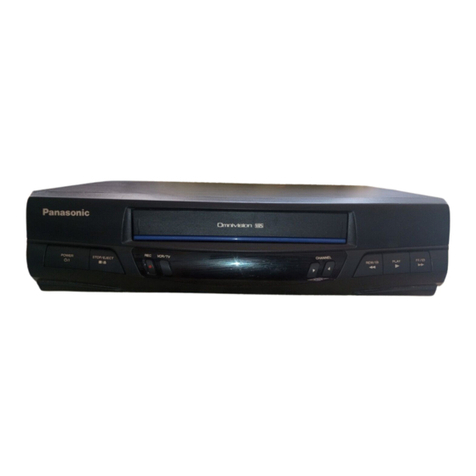
  9. Panasonic NV-FJ623EC User manual

Panasonic NV-FJ623EC User manual

This manual suits for next models

1

Other Panasonic VCR System manuals

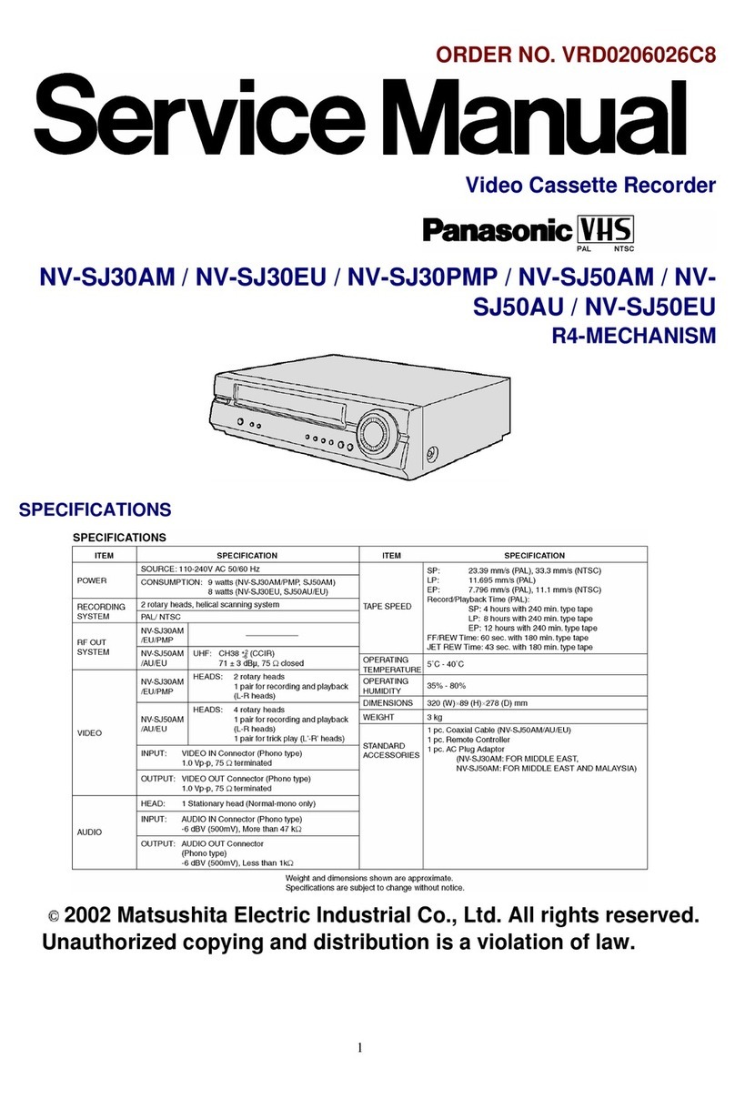
Panasonic OmniVision PV-QV200 User manual

Panasonic

Panasonic OmniVision PV-QV200 User manual

Panasonic AJ-HD150FE User manual

Panasonic

Panasonic AJ-HD150FE User manual

Panasonic NV-FS1 Series User manual

Panasonic

Panasonic NV-FS1 Series User manual

Panasonic OmniVision PV-QV201 User manual

Panasonic

Panasonic OmniVision PV-QV201 User manual

Panasonic ProLine AG-1980P User manual

Panasonic

Panasonic ProLine AG-1980P User manual

Panasonic Omnivision PV-8200 User manual

Panasonic

Panasonic Omnivision PV-8200 User manual

Panasonic Omnivision PV-S4680 User manual

Panasonic

Panasonic Omnivision PV-S4680 User manual

Panasonic NV-HD675 Series User manual

Panasonic

Panasonic NV-HD675 Series User manual

Panasonic Omnivision PV-V4601 User manual

Panasonic

Panasonic Omnivision PV-V4601 User manual

Panasonic NV-HD100EA User manual

Panasonic

Panasonic NV-HD100EA User manual

Panasonic PV-V4623S-K User manual

Panasonic

Panasonic PV-V4623S-K User manual

Panasonic ProLine AG-2560 User manual

Panasonic

Panasonic ProLine AG-2560 User manual

Panasonic Omnivision PV-V4020 User manual

Panasonic

Panasonic Omnivision PV-V4020 User manual

Panasonic AJ-YA120AG User manual

Panasonic

Panasonic AJ-YA120AG User manual

Panasonic Omnivision PV-8401 User manual

Panasonic

Panasonic Omnivision PV-8401 User manual

Panasonic PV-8660 User manual

Panasonic

Panasonic PV-8660 User manual

Panasonic Quasar PVQ-1310 User manual

Panasonic

Panasonic Quasar PVQ-1310 User manual

Panasonic AG-6840 User manual

Panasonic

Panasonic AG-6840 User manual

Panasonic NV-FJ620AM User manual

Panasonic

Panasonic NV-FJ620AM User manual

Panasonic NV-HD70EA User manual

Panasonic

Panasonic NV-HD70EA User manual

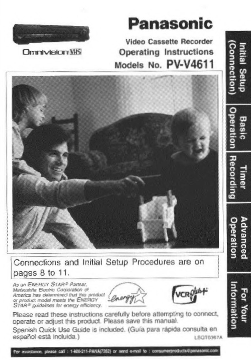
Panasonic Omnivision PV-V4611 User manual
Panasonic

Panasonic Omnivision PV-V4611 User manual
Panasonic PV-V4525S User manual

Panasonic

Panasonic PV-V4525S User manual

Panasonic AJ-HD1500P User manual

Panasonic

Panasonic AJ-HD1500P User manual

Panasonic AG710 - INDUSTRIAL VHS User manual

Panasonic

Panasonic AG710 - INDUSTRIAL VHS User manual

Popular VCR System manuals by other brands

RCA VR678HF user guide

RCA

RCA VR678HF user guide

Zenith VRL4270HF Operating guide & warranty

Zenith

Zenith VRL4270HF Operating guide & warranty

Akai VS-606EA Operator's manual

Akai

Akai VS-606EA Operator's manual

FUNAI 27C-450 Service manual

FUNAI

FUNAI 27C-450 Service manual

Sanyo VHR-M262EV Service manual

Sanyo

Sanyo VHR-M262EV Service manual

Sony SLV-X37 operating instructions

Sony

Sony SLV-X37 operating instructions

JVC SR-VS20U - Dual Format S-vhs/minidv Recorder instructions

JVC

JVC SR-VS20U - Dual Format S-vhs/minidv Recorder instructions

Grundig GV 7400 EURO Service manual

Grundig

Grundig GV 7400 EURO Service manual

Zenith VCM321 Installation and operating guide

Zenith

Zenith VCM321 Installation and operating guide

JVC HR-A43U, HR-A63U instructions

JVC

JVC HR-A43U, HR-A63U instructions

Aiwa VX-S135U operating instructions

Aiwa

Aiwa VX-S135U operating instructions

RCA VR725HF user guide

RCA

RCA VR725HF user guide

JVC 0703-AH-PJ-BJ instruction manual

JVC

JVC 0703-AH-PJ-BJ instruction manual

TruTech ZV450TT8 owner's manual

TruTech

TruTech ZV450TT8 owner's manual

JVC HR-DVS1EK instructions

JVC

JVC HR-DVS1EK instructions

Sensory Science DDV2120 user guide

Sensory Science

Sensory Science DDV2120 user guide

JVC HR-VP78U instructions

JVC

JVC HR-VP78U instructions

RCA VR611HF user guide

RCA

RCA VR611HF user guide

manuals.online logo
manuals.online logoBrands
  • About & Mission
  • Contact us
  • Privacy Policy
  • Terms and Conditions

Copyright 2025 Manuals.Online. All Rights Reserved.

ORDERNO. VRD0202005C2
Video Cassette Recorder
NV-FJ623EC / NV-FJ623ECN
Z-MECHANISM
SPECIFICATIONS
2002 Matsushita ElectricIndustrial Co., Ltd. All rights reserved.
Unauthorized copying and distribution isaviolation of law.
1
1. INTRODUCTION
This service manual contains technical information whichwill allowservice personnel to
understand and service this model.
If the circuit is changedormodified, this information will be followedbysupplementaryservice
manual tobe filedwithoriginal service manual.
Note:
Adjustment procedures, DisassemblyProcedures and AssemblyProcedures forMechanism
Chassis are separate volume fromthis service manual.
Please refertothe service manual forZ-MechanismChassis. (OrderNo. VRD9802005C2)
2. GENERAL DESCRIPTIONS
2.1. SERVICECAUTION
2.1.1. REPLACING IC7702/EEPROM
Whenthe EEPROM: IC7702 is replaced, applicable model code, option code and electrical
adjustment data will not be available.
Therefore, enterand/oradjust the necessarydata afterreplacing IC7702 byreferring following
procedure.
STEP1.REPLACE THE IC7702
1. Remove the C.B.A. with Mechanism unitbyreferring the
Disassemblyprocedure.
2. Disconnect the AC plug and replace the IC7702.
STEP2.INPUTTHE MODEL& OPTION CODE
1. Set up the applicablemodel code and option code byordering the
following table.
2
PROCEDURE F.I.P. DISPLAY
Turnon the Service Mode
1.Press the FF keyand the
EJECTkeysimultaneouslyfor
more than3 seconds.
Activate the Service Mode 2
2.While keepplacing FF key,
press the EJECTkeyintwice.
Activate the Entering Mode.
3.Press the EJECTkeyformore
than3 seconds.
Set the Mode 2.
4.Press the CH UP keyintwice.
Displaythe Setting Code.
5.Press the POWER Button to
turnthe poweron.
(Colon starts
flashing)
Enterthe Model and Option Code.
6.Service Screenis displayedon the monitor.
7.Set the applicable Model and Option code by
using REW, PLAY, STOP and FF keys on
theRemote Controller. (See Fig.S1 & S2)
Exit fromService Mode.
8.Press the POWER Button to
turnthe poweroff.
9. Press FF and EJECTkeys
simultaneouslyin6 times.
(Normal
Indication)
Fig.S1 Service Screen(sample)
3
Model No. Model
/ Code Option
Code 1 Option
Code 2 Option
Code 3
NV-FJ623EC/ECN 66
(42h) 125
(7Dh) 196
(C4h) 6
(6h)
Fig. S2 Model Code & Option Code
NOTE:
Since all electrical adjustments data is still not available, perform the Electrical Adjustment
continuously.
2.1.2. CYLINDER UNITREPLACEMENT
1. CYLINDERUNITREPLACEMENT
A. Remove the mechanism unitfrom MAINC.B.A./Chassisby
referring “SECTION2. DisassemblyProcedure”.
B. Remove the 3screws(A)of the CYLINDERUNITwith ascrew
driver.
C. Unlock the 4locking tabs (B)and disconnect the Cylinder
flexiblecard from the FPCHolder.
D. Remove the CYLINDERUNIT.
CAUTION:
Handlethe Cylinder flexiblecard with care. When itdamaged, you
shouldreplace wholeCylinder unit.
Fig. S3
2. UPPERCYLINDERDISASSEMBLY
A. Remove 2screws(A).
B. Remove the Cylinder Stator Unit.
4
C. Remove 2screws(B).
D. Remove the Cylinder Rotor Unit.
E. Loose Hex screw (C)(1.5mm) and remove the CYLINDER
RETAINER.
F. Remove the Upper Cylinder. Fig. S4
3. UPPERCYLINDERASSEMBLY
When reassembling, perform the steps inthe reverse order.
Notes:
1. Install the Cylinder Retainer so that the 2holes on top of the
5
Cylinder Retainer are at right angles with the P3502 Connection.
2. Tighten the Hex screw (C)(1.5mm) whilepressing downon top of
the Cylinder Retainer. Fig. S5
3. Install the Cylinder Rotor Unitso that the inner holeof the
Cylinder Rotor Unitfits to the small projection (D)on top of the
Upper Cylinder.
4. Tighten 2screws(B). Fig. S6
5. install the Cylinder Stator Unit.
6. Tighten 2screws(A). Fig. S7
6
7. Confirm the PG SHIFTERADJUSTMENTwith the alignment tape
(PAL: VFJ8125H3F) and adjust itifnecessary.
2.1.3. CHECKING OFMAIN C.B.A.
Whenservicing the MAIN C.B.A., take out the MAIN C.B.A. and mechanismfromthe frame and
turnover.
Fig. S8
2.1.4. FLATCARD CABLE INSTALLATION
Wheninstalling the Flat CardCable on the connector, install the Flat CardCable withthe cable
contacts facing the connectorcontacts.
Fig. S9
2.2. REMOVALOFCASSETTE TAPE
7
There are 2 ways toremove a cassette tape.
1. Service Information DisplayOperation
A. Press the FF and EJECTkeyssimultaneoslyfor 3seconds and
set the Service Mode 7.
B. Press STOPkeyinorder to rotate the Loading Motor for
unloading operation. (Payan attention of tape slack)
2. Manual Operation
A. Disconnect the AC Mains Lead and remove the Top Panel.
B. Rotate the MainCam Gear clockwise until the Loading Posts
move to fullyunloaded position as shownin Fig. S10 . (Tape is
remaining) Fig. S10
C. Rotate the Capstan Motor clockwise from the bottom side to
take up the tape. Fig. S11
D. Rotate the MainCam Gear clockwise until the cassette tape is
ejected.
2.3. INTRODUCTIONOFVIDEO HEAD CLEANING CASSETTE /
(POLISHING TYPE)
1. We are pleased to introduce PanasonicVideo Head Cleaning
Cassette, VFK0923FT [for service purposes] and VFK0923FSE [
for end users] for all VHS/SVHSVCPand VCR.
8
2. These cleaning cassettes are exclusive removing the hard and
stickyclogging on video heads.
3. These improve the efficiencyof video head cleaning service and
shortening cleaning time for end users.
VFK0923FT
(ForService usage)
Type of Cassette Full VHS Cassette
Cleaning Time 10 Seconds/Time
Tape Length 20 m
Usabilityina Path 180 Times
VFK0823FSE
(Forend users)
Type of Cassette Full VHS Cassette
Cleaning Time 10 Seconds/Time
Tape Length 3.34 m
Usabilityina Path 30 Times
9
VFK0823FSE
(Forend users)
Note:
The tape material itselfisthe same inboth types.
2.4. SELF-DIAGNOSISRESULT DISPLAY
The "SELF-DIAGNOSIS RESULT DISPLAY & MEMORY function is built inthis VTR.
It means that whenthe VCR detects undesirable condition, it canbe displayeda “Errorcode
(Twonumbers fromthe right)” withService Mode 2.
Since the "Errorcode" is storedinthe EEPROM, it canbe displayedalthough after
disconnectedthe AC leads. It canbe displayedwithService Mode 2.
(If a second errorhadbeendetected, onlythe most recent erroris displayed. )
Formore details, refertothe Service Manual forZ-MechanismChassis Ordernumber
VRD9802005C2.
10